plastic injection molding and manufacturing

Injection Molding

Injection moldingis amanufacturingprocess for producing parts by injecting material into a mold. Injection molding can be performed with metals,glasses, confections, andplastic thermoforming. Material for injection molding parts is fed into a heated barrel, mixed, and then forced into a mold cavity where it cools and hardens to the specifications of the cavity.

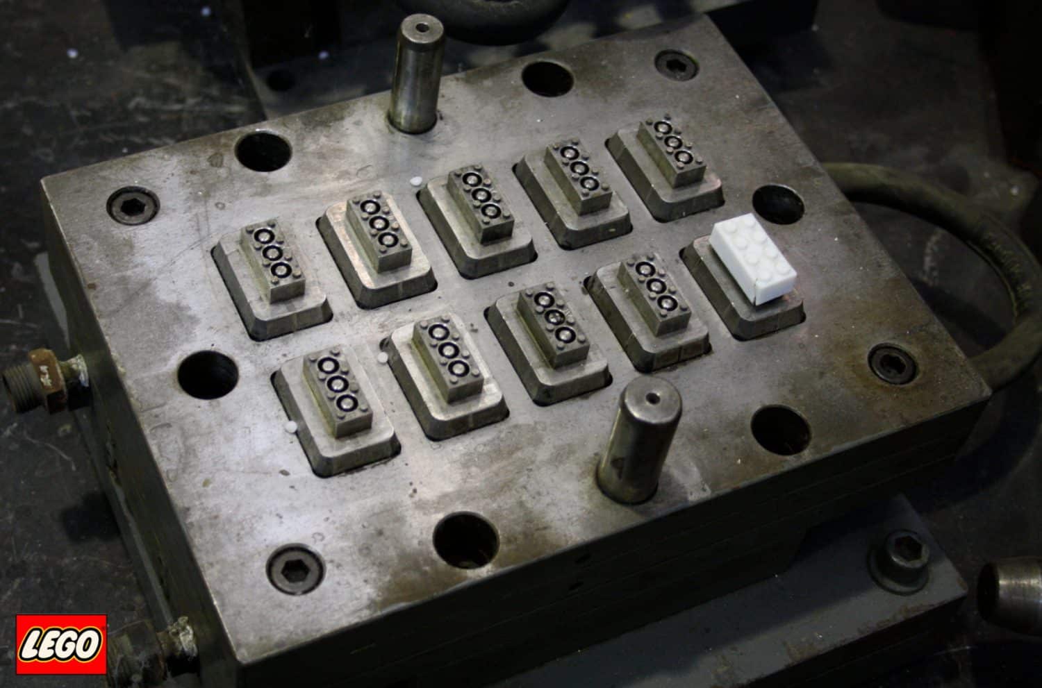
After an engineer designs a product, molds are made by a toolmaker from steel or aluminum. After the mold is made it is precision machined to form the features of the desired part. Injection molding is used for manufacturing a variety of parts, from small components to body panels for automobiles. Technology advances in3D printing using photo polymers can also be used for some simple injection molds. Photo polymers are used because they do not melt during the injection molding of some lower temperature plastic thermoforming processes.

Injection molding parts must be carefully designed to facilitate the molding process to prevent defective parts manufacturing. The material used for the part, shape, features, mold material, and the properties of the molding machine must all be taken into consideration. The versatility of injection molding is facilitated by this compass of design considerations and possibilities.

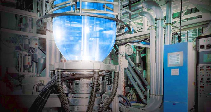
Injection molding uses a ram or screw type plunger to force molten plastic material into a mold cavity. The material then solidifies into a shape that has conformed to the design of the mold. Injection molding is most commonly used to process plastic thermoforming in terms of total annual material volumes processed. Plastic thermoforming is prevalent because its characteristics make them highly suitable for injection molding; such as the ease with which they may be recycled, versatility allowing them to be used in a wide variety of applications,and their ability to soften and flow upon heating. Plastic thermoforming is also much safer than thermosetting because if a thermosetting polymer is not ejected from the injection barrel in a timely manner,chemical crosslinkingmay occur causing the screw and check valves to quit performing and potentially damaging the injection molding machine.

All injection molding processes can produce flawed parts. Troubleshooting is performed by examining defective parts for specific defects and addressing these defects with the design of the mould or the mold characteristics. Tests are performed before full production cycles begin in an effort to predict defects and determine the appropriate specifications to use in the injection process.

Industrial Drives For Injection Molding

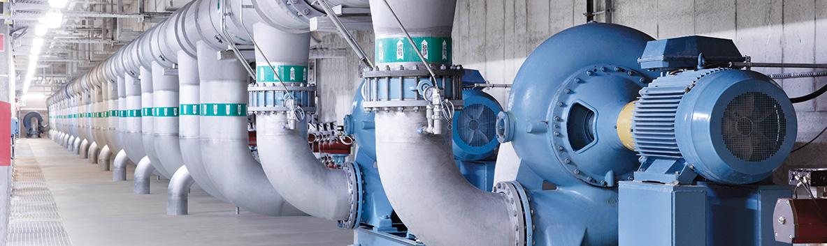
Industrial variable frequency drives (VFD’s) enable uncompromised productivity for allinjection molding processes.The ABB ACS880 drive is compatible with virtually all injection molding processes, automation systems, users and factory requirements. ABB ACS880 industrial drives are designed to simplify injection molding operation, optimize energy efficiency and help maximize production output. The ABB ACS880 series consists of single drives, multiple drives and drive modules.ABB general purpose industrial drives are designed for motor control and energy savings. ABB general purpose drives offer plug and play motor control convenience, straight from the box. ABB general purpose drives are a self-contained solution for injection molding applications. ABB general purpose drives and ABB ACS880 drives offer built in features to simplify drive selection, installation and use for injection molding.

For injection molding equipment repair and replacement quotes, contact Precision Electric. ForABB industrial drive repair and replacement quotes, contact Precision Electric.

Harmonic Distortion

Harmonic Distortion is any distorted voltage and current waveform that deviates from an ideal sinusoidal waveform. Harmonic distortion presents potential harm and equipment downtime to electrical components. Non-linearloads connected to the electrical supply in facilities cause harmonics (waveform distortions) on the power distribution system. Common non-linear loads include solid state motor soft starters, variable frequencydrives, computers, electronic lighting, welding supplies and uninterrupted power supplies.

The Institute of Electrical and Electronics Engineers (IEEE) has established a recommended practice – IEEE 519-2014- which sets limits for harmonic current and voltage distortion for electrical power systems.This recommended practice provides the foundation for evaluating the level of harmonic distortion in a power distribution system, and the level of action required to mitigate the risks.Industries such as water and waste water treatment, and HVAC, must meet local requirements to achieve low harmonic levels; this prevents disturbances to equipment in nearby residential properties and commercial buildings.Harmonic distortion can impact a system in many ways: it can cause distribution transformers to overheat, resulting in insulation breakdown and failure; electronic displays and lighting may flicker; nuisance tripping of circuit breakers is possible; and damage can occur to electronic equipment. Harmonic distortion effects are not limited to the facilities where electrical equipment is installed. This potentially impacts any residential and commercial areas, where electrical equipment is installed such as: pumping stations, waste water treatment plants, cooling towers and HVAC systems.

Harmonic Distortion Reduction

Professionals responsible for designing and maintaining electrical systems must be aware of the potential issues related to harmonic distortion of their power distribution systems; and know how to manage them in the most efficient and cost effective manner.Many factors and components impact the overall quality of a power distribution system. Variable frequency drives (VFD’s) are among the many electrical devices included in that group. Manufacturers of variablefrequency drives offer a variety of answers to the question of how to reduce the levelof distortion these devices produce. Most of these solutions involve adding large, costly components like specialty transformers to the variable frequency drive installation to reduce the level of harmonic distortion.

ABB offers a broad range of Ultra Low Harmonic drive solutions. ABB ULH drives have built-in components to reduce harmonic distortion. ABB ULH drive solutions provide the best combination of harmonic reduction, package size, weight and range of features.The ABB Ultra-low Harmonic drive solution provides the best overall management of harmonic distortion of all solutions tested. Not only are the current and voltage distortions minimized, but the power factor is controlled to operate at unity (1.0), minimizing the total current used by the drive. ABBULH drives are the ideal solution for those drive installations where low harmonic content is desired or mandated. Its footprint is generally smaller than com parable stand-alone installations that use additional bolt-on harmonic reduction means. Its performance and simplicity of installation make it suitable for the water and wastewater industry, which includes applications such as: pumps, blowers, and compressors.

For more information about harmonic distortion or for variable frequency drive repair and replacement quotes, contact Precision Electric.


Altivar VFD

The Altivar VFD Plus enclosed drives feature the Altivar 61 and Altivar 71 power converters. The Altivar VFD Plus enclosed drives provide a packaged adjustable speed drive solution for commercial, industrial, and municipal applications. The Altivar VFD Plus drives combine the reliability and ease of use of the Altivar drives family with proven, validated, and tested drive system designs. Altivar Plus enclosed drives are pre-engineered, ready to use solutions in highly efficient designs. Altivar VFD Plus enclosed drives are tested and validated before shipment to ensure smooth installation. Altivar VFD Plus enclosed drives are modular and compact to maximize space utilizationand easy to set up and commission with intuitive operator interface. Altivar VFD Plus enclosed drives are available from 125 hp to 2500 hp in 460 Volt and 600 Volt. The low voltage Altivar VFD Plus series engineered drives provide a high level of performance focusing on higher horsepower ratings in a Nema Type 12 enclosure.

Altivar VFD, CPD Series

For municipal and industrial pumping applications, the Altivar VFD, CPD Series drive is an 18-Pulse enclosed drive controller features the new Telemecanique brand Altivar 61 and 71 power converters. Schneider Electrics experience and expertise in power distribution and power quality measurement are combined with solid state motor control. The Altivar VFD, CPD series drive is a robust, packaged, adjustable speed drive with clean power. Altivar CPD Series 18-Pulse drives are ideal for installations specifying clean power low- harmonic content in compliance with IEEE 519 guidelines for harmonic mitigation. Altivar VFD, CPD Series 18-Pulse drives are UL508 listed and feature a heavy-duty industrial disconnect handle with lock-out/tag-out provisions. Altivar VFD, CPD Series 18-Pulse enclosed drive controllers are low voltage products and are available in 40 horsepower through 450 horsepower in 460 Volt.

Altivar VFD, M-Flex

The Altivar VFD, M-Flex series enclosed drive features either the Altivar 61 or Altivar 71 power converters. The Altivar VFD, M-Flex series drives are either within a Type 1 general purpose or Type 12/12K drip/dust proof enclosure with an integrated or barrier design. Altivar VFD, M-Flex series drives offer a platform of standard, engineered and special features to meet the varied needs of commercial, industrial and municipal process applications where high functionality of features is required. M-Flex enclosed drive controllers are low voltage products available in ratings from 1hp through 450 hp, 460 Volt, and 1hp to 40 hp, 208/230 Volt. Altivar VFD, M-Flex series drives for variable torque (Light duty, 110% current limit) are available in ratings from 1hp to 500 hp, 460 Volt, and 1hp to 50 hp, 208/230 Volt. Integrated enclosures can be wall or floor mounted, depending on size. They provide a circuit breaker disconnect and enough room for power peripherals, including isolation and bypass contactors, all within the same enclosure. Barrier enclosure Altivar VFD M-Flex series drives separate power and control circuits, such as bypass, from the drive control. The separate compartments allow for maximum flexibility if servicing a drive in bypass operation.

To learn more about Altivar VFD drives, please visit the Altivar Website. For Altivar VFD Repair and Replacement quotes, call Precision Electric.

Plastic Thermoforming

Plastic thermoforming is a process of manufacturing where a plastic sheet is heated to a flexible temperature, molded to a specific shape, and trimmed to create an end product. Complex and high-volume plastic thermoforming applications can manufacture thousands of finished products per hour depending on machine, mold size, and the size of the units being formed.
Thin-gauge plastic thermoforming is primarily used to manufacture products for food, medical, and other related industries. Thick-gauge plastic thermoforming is used to manufacture vehicle doors, vehicle dash panels, refrigerator liners, utility vehicle beds, plastic pallets, and other related products.

Thin-gauge plastic thermoforming uses plastic sheets that are fed from a roll or from an extruder into a group of indexing chains that incorporate pins to puncture the sheet and move it through an oven for heating to a molding temperature. The hot sheets are then indexed into a form station where a partner mold and pressure-box close on the sheet, with vacuum then applied to remove trapped air and to pull the material into the mold along with pressurized air to form the plastic to the detailed shape of the mold.

After the form cycle, a gust of reverse air pressure is propelled from the vacuum side of the mold as the form tooling opens to break the vacuum and assist the formed parts off the mold. Stripper plates may be utilized on the mold as it opens for ejection of more precise parts or those with negative-draft, undercut areas. The plastic sheet containing the formed parts then indexes into a trim station on the same machine, and a die cuts the parts from the remaining sheet web, or indexes them into a separate trim press where the formed parts are trimmed. The sheet remaining after the formed parts are trimmed is usually wound onto a reel or fed into an inline granulator for recycling purposes.Most plastic thermoforming manufacturers recycle their wasted scrap by compressing in a baling machine or by feeding into a granulator and producing ground flake, for sale to reprocessing companies, or they re-use it in their own facility. Most scrap and wasted plastic from the thermoforming process is converted back into extruded sheet for forming again.

For plastic thermoforming equipment retrofitting, repair and replacement quotes, contact Precision Electric, Inc.

Adjustable Speed Drive Repair

Checking connections is a step many people miss or do incorrectly during anadjustable speed drive repair process. Heat cycles and mechanical vibration can lead to sub-standard connections, as can standard preventative maintenance practices. Reusing torque screws is not a good Idea, and further tightening an already tight connection, can ruin the connection. Bad connections eventually lead to arcing. Arcing at the drive input terminal can result in nuisance over voltage faults, clearing of input fuses, or damage to protective components. Arcing at the drive output terminal could result in over-current faults or even damage to the power components.Loose connections can cause erratic operation. For example, a loose START/STOP signal wire can cause uncontrollable drive starting and stopping. A loose speed reference wire can cause the drive speed to fluctuate, resulting in scrap, machine damage, or personnel injury.

Conduct Diode and IGBT Tests
There are a number of methods to test the input and output power sections of an ajustable speed drive, and this step is essential prior to applying power to the drive unit. If for any reason there is a short on the input side or output side of the drive, further damage can be caused to the unit if power is applied to it.For this reason, Precision Electric uses meters to properly test the input and output power sections of the adjustable speed drive prior to applying power to the actual unit. If a short is found, the unit can be disassembled and the cause of the short can be diagnosed and quoted for repair. If the repair is too costly, then a replacement is offered to the customer.

Power Up Unit
If the input and output power sections on the adjustable speed drive test healthy during this step of the repair process, Precision Electric will power the unit and perform amp reading and output frequency tests. Precision Electric prefers to slowly increase power voltage to the unit until the rated input voltage of the drive is achieved. Depending on whether or not the adjustable speed drive provides a display will determine what further action(s) will be taken. If display is unavailable, disassembly and diagnosis of the internal power supply of the control section of the drive is likely necessary to further evaluate cause of failure and establish cost and lead time for the repair.

Run A Motor
If the previous three tests have passed during the adjustable speed drive repair process, then it is time to run a basic jog function of the drive with a simple template program. Often when an adjustable speed drive comes into our facility, we make sure to backup all existing programs stored in the drive prior to inputting a template program and running a test procedure. This ensure we have a backup copy of the program.The best method for backing up depends on the brand of drive, but after it has been backed up, we either reset the adjustbale speed drive to factory defaults through the keypad and recommission a basic start, stop and job application or closed loop if an encoder is involved. If the motor will not run, it will be necessary to check the output voltages and current ratings going to the motor to see if the drive is functioning properly to rotate the motor.

Contact Customer
At this point we have determined the cause of failure, estimated lead time and cost of the adjustable speed drive parts that need replaced, and are ready to offer the customer our repair quote. If the adjustable speed drive has tested good entirely, then further underlying issues are communicated with the customer. This is when Precision Electric will gather application specific information from the customer to establish whether or not it may be some outside issue associated with the system including, but not limited to, PLC communications, faulty I/O, bad wiring or even bad cabling. There is no single way to do this step since it depends on a wide variety of variables.

Routine Maintenance
Most adjustable speed drive repair can be prevented with routine maintenance. Adjustable speed drive repair cost and lead times can also be reduced with routine maintenance. Adjustable speed drive repair can be expensive and also cost manufacturers production downtime during the repair process. Most manufacturers keep spare drives in stock to prevent production downtime when their adjustable speed drive repair is in process.

Adjustable speed drive repair should be taken with extreme caution. Adjustable speed drive repair should only be performed by technicians who have required training and experience to work with electrical equipment. Precision Electric strongly recommends to consult an expert in the field when repairing all industrial electrical equipment. Many drive controllers have an internal DC bus that retains a charge after power has been cut to the drive, as a result, it does not mean it’s safe to work with. Technicians working with drive repair must always take extra precautions to ensure proper safety measures are taken, or injury or even death may occur.

For adjustable speed drive repair and replacement quotes, contact Precision Electric, Inc.

Precision Electric Now Supplies ABB ACS550 Series Drives

acs550We’re pleased to announce the addition of ACS550 Series Variable Frequency Drives to our online sales product line. The ACS550 Drives is a long time player from the line of ABB variable frequency drives and go up to 550 horsepower. This drive is a great fit for users who are used to the ABB brand of variable frequency drives and are looking for a cost-effective solution for running their motor application.

The ABB ACS550 Series drive finds it’s place as a mid-level applications drive. Typically it is used for open loop applications rather than closed loop. There is an optional encoder card though for users who find themselves in need of a closed loop setup of their motor and drive.

As with the majority of variable frequency drives out there, such as the SMVector, the ACS550 also comes with threeoperating modes. These operating modes include standard V / Hz control, variable torque controlandopen loop vector control. An integrated line filter (or EMC filter) comes standard onany model in an R2 frame or smaller. All boards are coated for harsh environments and each ACS550 includes a swinging choke for superior harmonic reduction.

If you find yourself wanting to know more information on the ACS550 drive simply swing by anyACS550 product page to learn more, you can also grab the manuals while you’re there to get an idea of how to setup your drive. One of the unique features of all ABB drives is the macro system for setting up applications, such as pumps or fans. Each drive comes with preset macros that make the configuration and startup the drive simple.

One confusing aspect of ABB drives is that they tend to come in two separate ratings. There is a “standard rating” and a “heavy duty rating” – heavy duty ratings are typically reserved for applications that are variable torque and may endure extreme loads for up to 10 minutes. To be exact, the ACS550 heavy duty ratings allow for 150% short term overload ratings from 1 to 10 minutes. Since we aren’t always able to know the application our customers are implementing these drives into all ratings at our site are specified at heavy duty.

The ACS800 variable frequency drive is a newer product for those looking for a possible replacement or upgrade of their ACS550 drive. The ACS800 is defined by us as an applications drive. This drive has just about every feature a modern variable frequency drive can have. This includes the integration of a full range of applications and extensive quantity of accessories to make it compatible with almost any industrial system. For the longest time the ACS800 has been ABBs go to drive.

ABB Plastic Process Equipment

ABB plastic process equipment is available in a complete range of solutions developed to meet the specific needs of the plasticsproduction industry, including AC and DC drives, controls and safety engineering. ABB plastic process equipment userscan meet all drive and control needs from a single source. They can also call on the extensive global technical application and service support delivered by ABBs team ofhighly skilled and knowledgeable engineers who have a wealth of experience in the plastic manufacturing industries.

ABB plastic process equipment includes ABB robots for the entire spectrum of mould machines – small, medium-size and heavy duty. A glance at the typical applications reveals true robot versatility: insertion of parts in the mould, extraction and a wide variety of post-process applications such as cutting, gluing, assembly and quality control. Since these machines can be floor-mounted, mounted on pedestals or shelfmounted, the user still retains maximum flexibility. Additional ABB plastic process equipment with extended cycle time simply extends the performance of ABB 6-axis robots; to a perfect blend of accuracy and consistency.

Different types of ABB plastic processequipment is employed depending on the plastic product, type and size of its corresponding extruder. A diverse range of motors are used: standard IEC asynchronous motors, square type servo motors, DC motors, permanent magnet motors, and synchronous reluctance motors. Drives are used for precise motor control and increased energy efficiency as well as for environmental and cost reasons. Modern drives also provide dynamic torque limiting for the extrusion screw even without speed feedback, even with synchronous motors with or without permanent magnets. For extruder heating systems, ABB plastic process controls with adaptive thermostats offer particular advantages.

ABB Control Builder Plus is ABBs unique integrated engineering tool for control systems, drives, operating panels, field buses, network and webservices. It integrates tools for the configuration, programming, diagnostics and servicing of almost every automation project via an intuitive user interface. ABB’s dynamic control of asynchronous, PM servo motors and ABB synchronous reluctance motors enables the rapid correction of load-side disturbances. ABB drives with direct torque control (OTC) provide speed and torque control without sensors.

ABB plastic process equipment is flexible to optimize all manufacturing processes and control. ABB plastic process equipment also comes with premium service, responsible solutions and expertise at the user’s disposal, anywhere on the globe. To learn more about ABB plastic process equipment, visit the ABB Website. For ABB plastic process equipment repair and replacement quotes, contact Precision Electric, Inc.

Eaton Cold Weather Parameter

Eaton adjustable frequency drive products implemented an Eaton cold weather parameter functionality. The Eaton cold weather parameter function will provide the ability of the drive to function down below the initial rated temperature with a safe cost effective way to perform warming of both the motor and the drive cabinet.TheEatonDG1 adjustable frequency drive has a parameter group that supplys a selectable AC voltage to the motor at a very low frequency for a desired period of time and also lowers the temperature fault level.

This design uses the current draw through the IGBT modules to warm up the unit temperature by sending a 0.5Hz output frequency to the motor. The drives standard low temperature fault point is -10C which in most applications this is sufficient. In extreme temperature regions that often reach below this point, this can cause a fault, preventing operation of the drive. With the cold weather functionality enabled, the trip point is taken from a -10C fault level and moves it down to -30C with an alarm trip point at -20C. Therefore, the adjustable frequency drive will start the motor in a normal operational mode when the unit temperature is above the -20C level. If the drives unit temp is between -20C and -30C and the drive is stopped, when the run command is given the drive will go into the cold weather warm up feature to enable the motor to start when it reaches -20C.

Eaton Cold Weather Parameter Setup

There are four Eaton cold weather parameter options that are used to perform the cold weather protection functionality with the primary one being the under temperature fault condition setting. These parameters provide a safe way to warm up the drive instead of enabling full voltage output in cold environments. Each of these settings is described in detail below:

P9.23: Unit Under Temp Protection This parameter is used to define the function of the unit under temperature which is the highest drive heat sink temperature taken from the IGBT gate and a thermal temperature sensor in the power board. This parameter comes defaulted as a Fault but can be changed to No Action, a Warning, or Fault and Coast to a stop. To use the cold weather warm up feature, this parameter should be left on either one of the Fault actions. The No Action and Warning will allow the drive to start and run up to the set reference when the start command is given. This could potentially damage the capacitors and IGBT module.

P9.39: Cold Weather Mode This parameter is used to enable the cold weather warm up fea- ture when the Unit Under Temp Protection is set to one of the fault conditions. With this enabled, it causes the unit temperature trip to be adjusted from -10C to -30C. In addition, it activates a warm up sequence when the unit temperature is between -30C and -20C. When a run com- mand is given, the output frequency will be set to 0.5 Hz and run for a selectable voltage percent- age and time. It will also indicate the drive is in the mode with an Alarm 90 Cold Weather Warm in this operational state. Once temperature goes above -20C, the drive will ramp up to the set ref- erence value. If the temperature does not rise above -20C in the specified time, the drive will go into a Fault F13 Under Temp Fault which can be reset and the sequence could be repeated.

p9.40: Cold Weather Voltage Level This parameter is used to select the percentage of volt- age output the drive will provided at 0.5Hz when in the cold weather warm up mode. This value can be set from 0 to 20% of the motor rated voltage setting in the drive. This value should be set based off the ambient temperature and how quickly the user would like the drive to warm up. A higher voltage will cause more current to flow through the motor heating it up faster, but this also can cause additional heating which can cause increased winding wear over long periods of time. It is recommended that the voltage level be set to the lowest level that will effectively meet the users application requirements.

P9.41: Cold Weather Time Out This parameter is used to select the time limit for the drive to run at the 5Hz level at the selected voltage. This time can be set from 0 to 10 minutes, the longer the time the more likely the drive will warm itself up to a starting condition. However, as the time is increased, the motor life may be reduced due to significant heating of the motor windings over long periods of time. It is recommended that the voltage level be set to the lowest level that will effectively meet the users application requirements.

To learn more about the Eaton cold weather parameter function, visit the Eaton Website. For Eaton drive repair and Eaton drive replacement quotes, contact Precision Electric, Inc.

Drive System Integration

Drive system integration is becoming more complex and demanding with technology.Manufacturing in the future will be much more resourceful than todays factories. Manufacturers must reach increasingly higherrates of productivity and efficiency at the lowestpossible cost. At the sametime, the next stage of industrial manufacturing is just around the corner: Industry4.0; an initiative known as the Smart Manufacturing Leadership Coalitioncharacterized by smart factories and self organizing communities of machinery, driven by information that’s virtually generated.

Drive technology alone can’t overcomeall the new challenges needed in today’s manufacturing processes. What is needed is consistent integration of drive technology into the factory environment of the manufacturingprocess.This changewill turndrive system integration into success factors that will lead the way to the future of production. Drive system integrationhelps improve the productivity, efficiency,and competitiveness of industrial manufacturingand reduces labor hours which increases marketing andproduction time.Drive system integration engineers are experts in providing engineering studies to increase machine speed forincreased production and/or to improve machine tension control for improvement ofproduct quality while decreasing run time needed to manufacture. Consulting may be required to investigate the present machine operation and evaluation of product quality and potential to increase these components. Observations are determined and then documented with alternative solutions and recommendations for customerneeds.

Upgrading existing equipment or installation of new equipment can be a liability. Manufacturers may seekopportunitiesforsolutions to their equipment while maintaining current productiondemands. This can be achieved by working with aflexible drive systems integration supplier, with the knowledge and capabilities to provide workingspecifications on time.

ABB offers a variety of variable frequencydrives that areavailable around the world. ABB drives are seen in applications where control requirements andenvironmental conditions are applicable.To meet all areas in productionrequirements, ABB offersa wide range of application specific solutions, ranging frompump, fan, conveyor and compressor applications through todemanding machinery and marine solutions.ABB drive modules enable machine builders, drive system integration and panel builders to engineer and build drive cabinets using ABB technology. The ABB industrial drive and ABB machinery drive modules are specifically designed to fit cabinet constructions. The drive modules come with a range of accessories including supply units, inverters, braking options, filters, various I/O and communications.

ABB ACS800 industrial drives are available both as complete AC drives and as modules to meet manufacturingrequirements as a user, OEM or system integration redesigns. ABB ACS800 single drive modules configuration contains a rectifier, DC link and an inverter in one single AC drive unit. They can be installed without any additional cabinet or enclosure, available in wall-mounted, freestanding and cabinet-built constructions. They are specifically designed for industrial applications in process industries such as the pulp & paper, metals, mining, cement, power, chemical, and oil & gas.

The ABB website includes an ACS880 pricing and configuration tool, designed specifically for drive systemintegration specialists. It is easy to manage and update. It includes products and options, along with their selection rules and restrictions. Offers can be automatically generated as a Microsoft Excel worksheet.

To learn more about drive system integration or for drive system integration quotes, contact Precision Electric.

VFD Repair

Most VFD repair can be prevented with routine maintenance. VFD repair cost and lead times can also be reduced with routine maintenance. VFD repair can be expensive and also cost manufacturers production downtime during the VFD repair process. Most manufacturers keep spare VFD units in stock to prevent production downtime whenthe VFD repair isin process.

Connections
Checkingconnections is a step many people miss or do incorrectly during the VFD repair process. Heat cycles and mechanical vibration can lead to sub-standard connections, as can standard preventative maintenancepractices. Reusing torque screws is not a good Idea, and further tightening an already tight connection can ruin the connection.Bad connections eventually lead to arcing. Arcing at the VFD input could result in nuisance over voltage faults, clearing of input fuses, or damage to protective components. Arcing at the VFD output could result in over-current faults or even damage to the power components.

Loose connections can cause erratic operation. For example, a loose START/STOP signal wire can cause uncontrollable VFD starting and stopping. A loose speed reference wire can cause the drive speed to fluctuate, resulting in scrap, machine damage, or personnel injury.

Conduct Diode and IGBT Tests
There are a number of methods to test the input and output power sections of aVFD, and this step is essential prior to applying power to the VFD unit. If for any reason there is a short on the input side or output side of the VFD, further damage can be caused to the unit if power is applied to it.

For this reason, Precision Electric uses meters to properly test the input and output power sections of the VFD prior to applying power to the actual unit. If a short is found, the unit can be disassembled and the cause of the short can be diagnosed and quoted for repair. If the repair is too costly, then a replacement is offeredto the customer.

Power Up Unit
If the input and output power sections test healthy during this step of the VFD repair process, Precision Electric will power the unit and perform amp reading and output frequency tests. Precision Electric prefers to slowly increase power voltage to the unit until the rated input voltage of the VFD is achieved.

Depending on whether or not the VFD provides a display will determine what further action(s) will be taken. If display is unavailable, dis-assembly and diagnosis of the internal power supply of the control section of the VFD is likely necessary to further evaluate cause of failure and establish costand lead time for the VFD repair.

Run A Motor
If the previous three tests have passed during the VFD repair process, then it is time to run a basic jog function of the VFD with a simple template program. Often when a VFD comes into our facility, we make sure to backup whatever program is currently stored in the VFD prior to inputting a template program and running a test procedure. This ensure we have a backup copy of the program.

The best method for backing up depends on the brand of drive, but after it has been backed up, we either reset the VFD to factory defaults through the keypad and recommission a basic start, stop and job application or closed loop if an encoder is involved. If the motor will not run, it will be necessary to checkthe output voltages and current ratings going to the motor to see if the VFD is functioning properly to rotate the motor.

Contact Customer
At this point we have determined the cause of failure, estimated lead time and costof the VFD repair. If the VFD has tested good entirely, then further underlying issues are communicated with the customer. This is when Precision Electricwill gather application specific information from the customer to establish whether or not it may be some outside issue associated with the system including, but not limited to, PLC communications, faulty IO, bad wiring or even bad cabling. There is no single way to do this step, as it really depends on a wide variety of variables.

Send Service Tech
If the customer cannot establish failure on any other aspect of the machine and the VFD appears to test fine, then it may be necessary to send a field service technician on site to establish cause of failure. Field service technicians should betrained to troubleshoot any issue ranging from standard VFD repair, to advanced robotics, PLCs and more. Field technicians should also be trained to establish cause of failure and come up with solutions as quick as possible.

VFD repair should be taken with extreme caution. VFD repair should only be performed by technicians who have required training and experience to work with electrical equipment. Precision Electric strongly recommends to consult an expert in the field when repairing VFD equipment.Many VFD controllers have an internal DC bus that retains a charge after power has been cut to the drive, as a result, it does not mean it’s safe to work with. Technicians working with VFD repair must always take extra precautions to ensure proper safety measures are taken, or injury or even death may occur.

For VFD repair and VFD replacement quotes, contact Precision Electric.

Eaton DG1 Drives

Eaton DG1 drives are general purpose drives andare a part of Eatons next generation PowerXL Series of adjustable frequency drives. Eaton DG1 drives arespecifically engineered for todays more demanding commercial and industrial applications. The power unitmakes use of the most sophisticated semiconductor technology and a highly modular construction that can be flexibly adapted to meet the customers needs. The control module was designed to include todaysstandard communication protocols and I/O while still having the abilityto add additional option cards.Eatons patented Active Energy Control is also a standard feature on DG1 drives, offering customers increased efficiency, safety and reliability.These drives continue the tradition of robust
performance and raise the bar on features and functionality, ensuring the best solution at the right price. Eaton DG1 drive products range from 230 Volt through 125 horsepower; 480 volt and 575 volt through 250 horsepower. Eaton DG1 drives are standardNema 1 (IP21) enclosed. All Eaton DG1 drives come with an EMC filter and standard brake chopper.

Accessories – Eaton DG1 Drives

The PowerXL SeriesEaton DG1 drives can accommodate a wide selection of expanded and adapter option boards to customize the drive for your application needs. The drives control unit is designed to accept a total of two additional option boards. The PowerXL SeriesDG1 drives come with a factory-installed standard board configuration including the following:

Standard I/O:

  • 8DI, 1DO
  • 2AI, 2AO
  • Three relays

Standard communications:

  • Ethernet IP, Modbus TCP
  • RS-485: Modbus RTU
  • BACnet MS/TP

The IP54 option kit is used to convert a IP21to a IP54 drive. The kit includes cover, fan and grommets.The Eaton DG1 drives flange kit is used when the power section heat sink ismounted through the back panel of an enclosure. The kitincludes hardware, top flange plate, bottom flange plate andtwo side flange plates.The PowerXL Series PC Tool is designed for programming, controlling and monitoring of EatonDG1 drives. Features include loading parameters that can be saved to a file or printed,setting references, starting and stopping the motor, monitoring signals in graphical or textform, and real-time display.

To learn more about Eaton DG1 drives or for Eaton DG1 drive repair or replacement quotes, contact Precision Electric, Inc.

ABB Energy Saving Solutions

Nearly 70 percent of all industrial electrical energy use goes to powering electric motors. These motors are the workhorses of business, from pumps moving fluids to fans moving air to compressors, conveyors, and every type of machine that depends on rotational force to get its job done. More than 90 percent of industrial motors either cannot adjust their power consumption or use very crude methods to do so. Many always run at full speed, regardless of the actual output needed. In many applications, energy use can be cut to one- eighth just by reducing the motor speed by half.The most immediate, cost-effective and practical way to address the energy challenge is to grasp the opportunities for energy reduction that come from using energy more efficiently with available and proven technology. ABB energy saving solutions includes a variety of products and services. ABBs drives, motors and other technologies can help lower energy use by reducing power consumption and losses, improving productivity or through better management of equipment.

ABB energy saving solutions face today’s industry and commerce energy challenges. Pressures to reduce energy consumption, lower carbon dioxide emissions and provide secure power supplies are coming from governments, consumers, legislators and shareholders. All of these pressures are against a background of ever-rising energy prices and the dramatic effects climate change is having on the environment. As a result, industry and their consumers are demanding ever more energy-efficient products. ABB energy saving solutions consist of low voltage AC drives (variable frequency drives) and DC drives. AC and DC Drives are designed to run electric motors based on the processes current demands rather than running them at full speed and reducing output using mechanical controls like throttles, dampers or gears.

Drives reduce the output of an application, such as a pump or a fan, by controlling the speed of the motor, ensuring it runs no faster than it needs. Many motors are oversized to cope with a maximum demand that rarely or never occurs. The drive brings the motor speed down to match the actual demand needed by the application. This often cuts energy consumption by 50 percent and in extreme cases by as much as 90 percent.

When other control methods are used, such as dampers, vanes or valves, the motor runs at full speed and the flow of the output is mechanically restricted. For instance, the flow through a pipeline may be reduced by a valve. This is wasteful, because the motor keeps running at its nominal speed regardless of the demand. The pump delivers maximum output and the excess is reduced at the valve, where the surplus energy is wasted through friction.

The energy saving potential in industries and utilities is enormous just in motor-driven applications alone: hundreds of millions of electric motors driving machines, compressors, fans, pumps or conveyors in virtually every sector account for about 70 percent of all the electricity that industry uses. In addition to the energy savings, the drive delivers accurate control and less mechanical wear, reducing maintenance and extending the life expectancy of the system. ABBs product range, from 0.18 kW to 72 MW, is the widest available from any manufacturer, offering drives for every need. ABB energy saving solutions are easy to control and quantify. Many of ABBs drives have built-in energy calculators to monitor energy consumption and savings in kilowatt hours, local currencies and carbon dioxide reductions. The drives built-in energy calculators show actual results that can be used as a basis for future energy saving projects.

To learn more about ABB energy saving solutions, visit the ABB Website. For ABB saving solutions, ABB drive repair, or ABB drive replacement quotes, contact Precision Electric, Inc.