PET Blow Molding

The increasing requirements being placed on food and beverage manufacturingare accompanied by growing demands on the machines in the consumer goods industry. The endcustomers in this industry are demanding machines and production lines with maximum availability, while calling for flexible product retooling and formatchanges as well as simple, consistent operator control of the machinery. Long maintenance intervals, clear error messages, the speedy worldwideavailability of spare parts and enormous energy efficiency for the machines are also important for success. Only acompany that effectively masters all the challenges it faces can be successful in the marketplace.Lenze offers the most modern automation and motion technology for the consumer goods industry based on the three standards of cost awareness, maximumquality and flexibility.

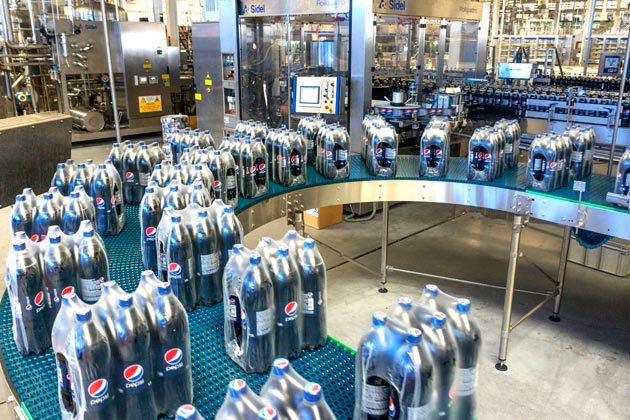
PET blow molding with Lenze Motion Centric Automation is a complete solution: bottles are formed, filled, capped and labeled. Motion Centric Automation from Lenze is the easy way to secure smooth procedures in almost anybeverage line. Lenze offers Motion Centric Automation products for PET blow molding to ensure that all processes remain simple and free of any problems.Motion Centric Automation from Lenze is a complete manufacturing solution from start to finish for PET blow molding processing. Below are the steps used with Lenze Motion Centric Automation products duringPET blow molding processing.

Applying even heat and air to create the perfect form is the first step in PET blow molding. The preforms are separated by the automatic preform loader and transported upwards to create the perfect form for PET blow molding process. Gravity thenallows them to slide into the in-feed wheel, from where they are loaded onto the transport chain. Infrared lamps in the heater heat up the preforms inrotation, whereby the neck of the bottles is held in shape at a lower temperature. The thermal treatment is combined with ventilation. At the heaterexit, arms of the PET blow molding carousel pick up the preforms below the neck. The form is completed and blowing process begins. The nozzle is lowered intothe preform and lateral pre blowing begins, followed by high pressure blowing, which presses the bottle wall against the mold. After cooling, an arm thenloads the bottles onto the transport chain.

Filling And Capping
Filling quickly, precisely and without interruptions: the empty PET bottles are conveyed to the filler carousel by the transport chain. The filler nozzleis quickly lowered into the empty bottle and starts to fill it, whereby a FlexCam cam profile ensures that any formation of foam is largely avoided.During the process, the nozzle is slowly moved up to match the fill level until the bottle is full.

When closing bottles at high speed, productivity is key: the transport chain moves the filled bottles to the capper. This presses the preheated caps overthe bottle thread and the bottles are then closed via torque-controlled rotation. Once this is complete, the closed bottles are sent to the labeler.Individual selection of drive components based on power requirements and the dynamic performance required. Highly dynamic servo drives and compact asynchronous motors with large speed setting ranges for all areas of bottle conveying benefit from a systematic arrangement: the finished bottles arrive in a single row, arranged one behind the other. The Cartesian coordinate robot picksup three or four bottles and lays them sideways onto a second conveyor belt. A touch probe sensor detects when enoughbottles are lined up at the end of the in-feed belt. The Cartesian coordinate robot then picks these up, controlled via a fixed motion profile for grouping.

Labelers
Precision is critical during wrap-around labeling: a rotary worm screw loads the bottles into the carousel, where they also rotate. In the labelingstation, a servo-driven transport roller continuously draws labels from the web, while the web guide guarantees straight-line label pick-up. The labelsare then cut to the precise size in a servo-controlled trimming process and two narrow strips of hotmelt adhesive are applied. The labels are thenapplied to the rotating bottles, after which the finished bottles are transported for secondary packaging.

Pick-And-Place
Benefit from a systematic arrangement: the finished bottles arrive in a single row, arranged one behind the other. The Cartesian coordinate robot picksup three or four bottles and lays them sideways onto a second conveyor belt. But how does the grouping work? A touch probe sensor detects when enoughbottles are lined up at the end of the in-feed belt. The Cartesian coordinate robot then picks these up, controlled via a fixed motion profile.

Film Wrappers
The next stage is packaging: here, the bottles previously arranged in groups of three or four arrive at the film wrapper lined up directly behind oneanother. The compartment conveyor chain ensures longitudinal grouping for packaging in 6-packs. The individual groups can now be wrapped in shrink film.The film is unwound and trimmed off by a servo-controlled cutter. The front edge of the film is then guided underneath the bottle group. A roller picksup the end by rolling over the pack and wrapping the film around it. The bottles are now ready for the shrink tunnel.

Shrink Tunnels
Everything needs to fit correctly: the bottles previously wrapped in shrink film are transported into the shrink tunnel.Under controlled and constant heat, the film shrinks to tightly fit the bottles. In the delivery area, the bundles created then cool down and are readyfor palletizing.

Palletizers
A parallelogram-type robot with reinforced base construction and sufficient arm length assumes responsibility for loading the pallet. The motion profilesof the robot kinematics can be calculated as axis movements and controlled using Lenze Controller-Based Automation with predefined profiles. Thesemovements are synchronized with the conveyor belt.

To learn more about PET blow molding or for Lenze Motion Centric Automation repair and replacement quotes, contact Precision Electric.

plastic injection molding and manufacturing

Injection Molding

Injection moldingis amanufacturingprocess for producing parts by injecting material into a mold. Injection molding can be performed with metals,glasses, confections, andplastic thermoforming. Material for injection molding parts is fed into a heated barrel, mixed, and then forced into a mold cavity where it cools and hardens to the specifications of the cavity.

After an engineer designs a product, molds are made by a toolmaker from steel or aluminum. After the mold is made it is precision machined to form the features of the desired part. Injection molding is used for manufacturing a variety of parts, from small components to body panels for automobiles. Technology advances in3D printing using photo polymers can also be used for some simple injection molds. Photo polymers are used because they do not melt during the injection molding of some lower temperature plastic thermoforming processes.

Injection molding parts must be carefully designed to facilitate the molding process to prevent defective parts manufacturing. The material used for the part, shape, features, mold material, and the properties of the molding machine must all be taken into consideration. The versatility of injection molding is facilitated by this compass of design considerations and possibilities.

Injection molding uses a ram or screw type plunger to force molten plastic material into a mold cavity. The material then solidifies into a shape that has conformed to the design of the mold. Injection molding is most commonly used to process plastic thermoforming in terms of total annual material volumes processed. Plastic thermoforming is prevalent because its characteristics make them highly suitable for injection molding; such as the ease with which they may be recycled, versatility allowing them to be used in a wide variety of applications,and their ability to soften and flow upon heating. Plastic thermoforming is also much safer than thermosetting because if a thermosetting polymer is not ejected from the injection barrel in a timely manner,chemical crosslinkingmay occur causing the screw and check valves to quit performing and potentially damaging the injection molding machine.

All injection molding processes can produce flawed parts. Troubleshooting is performed by examining defective parts for specific defects and addressing these defects with the design of the mould or the mold characteristics. Tests are performed before full production cycles begin in an effort to predict defects and determine the appropriate specifications to use in the injection process.

Industrial Drives For Injection Molding

Industrial variable frequency drives (VFD’s) enable uncompromised productivity for allinjection molding processes.The ABB ACS880 drive is compatible with virtually all injection molding processes, automation systems, users and factory requirements. ABB ACS880 industrial drives are designed to simplify injection molding operation, optimize energy efficiency and help maximize production output. The ABB ACS880 series consists of single drives, multiple drives and drive modules.ABB general purpose industrial drives are designed for motor control and energy savings. ABB general purpose drives offer plug and play motor control convenience, straight from the box. ABB general purpose drives are a self-contained solution for injection molding applications. ABB general purpose drives and ABB ACS880 drives offer built in features to simplify drive selection, installation and use for injection molding.

For injection molding equipment repair and replacement quotes, contact Precision Electric. ForABB industrial drive repair and replacement quotes, contact Precision Electric.

Lenze Drive Repair

Precision Electric offers Lenze drive repair because manufacturers cannot afford downtime when equipment fails. Most Lenze drives are replaceable but Lenze drives that aren’t in stock have extensive lead times. Lenze drive repair is usually less expensive than Lenze drive replacement.Precision Electric offers free Lenze drive repair quotes to customers who have failed Lenze equipment. The following is a list of steps Precision Electric uses for each Lenze drive repair.

Checking connections is a step many people miss or do incorrectly during Lenze drive repair. Heat cycles and mechanical vibration can lead to substandard connections, as can standard preventative maintenance practices. Reusing torque screws is not a good idea, and further tightening an already tight connection, can ruin the connection. Bad connections eventually lead to arcing. Arcing at the drive input terminal can result in nuisance over voltage faults, clearing of input fuses, or damage to protective components. Arcing at the drive output terminal could result in over-current faults or even damage to the power components. Loose connections can cause erratic operation. For example, a loose START/STOP signal wire can cause uncontrollable drive starting and stopping. A loose speed reference wire can cause the drive speed to fluctuate, resulting in scrap, machine damage, or personnel injury.

Conduct Diode and IGBT Tests – There are a number of methods to test the input and output power sections during Lenze drive repair, and this step is essential prior to applying power to the drive unit. If for any reason there is a short on the input side or output side of the drive, further damage can be caused to the unit if power is applied to it. For this reason, Precision Electric uses meters to properly test the input and output power sections of the drive prior to applying power to the actual unit. If a short is found, the unit can be disassembled and the cause of the short can be diagnosed and quoted for repair. If the repair is too costly, then a replacement is offered to the customer.

Power Up Unit – Before powering up the Lenze drive, programs and parametersthat can be salvaged from the drive should be backed up to a separate drive or computer. Then, if the input and output power sections test healthy during the Lenze drive repair, power is applied to the unit to perform amp reading and output frequency tests. Precision Electric prefers to slowly increase power voltage to the drive until the rated input voltage of the drive is achieved. Depending on whether or not the Lenze drive provides a display will determine what further action(s) will be taken. If display is unavailable, disassembly and diagnosis of the internal power supply of the control section of the drive is likely necessary to further evaluate cause of failure and establish cost and lead time for the repair.

Run A Motor – If the previous tests have passed during the Lenze drive repair process, then it is time to run a basic jog function of the drive with a simple template program. After the drive programs and parameters are backed up and saved, we either reset the adjustable speed drive to factory defaults and recommission a basic start, stop and job application or closed loop if an encoder is involved. If the motor will not run, it will be necessary to check the output voltages and current ratings going to the motor to see if the drive is functioning properly to rotate the motor.

Contact Customer – At this point we have determined the cause of failure, estimated lead time and cost of the parts that need replaced for the Lenze drive repair, and are ready to offer the customer our repair quote. If the drive performs perfectly during the entire repair process, then further underlying issues are communicated with the customer. This is when Precision Electric will gather application specific information from the customer to establish whether or not it may be some outside issue associated with the system; such as PLC communications, faulty I/O, bad wiring, bad cabling. There is no single way to do this step since it depends on a wide variety of variables.

Lenze drive repair should be taken with extreme caution. Drive repair should only be performed by technicians who have required training and experience to work with electrical equipment. Precision Electric strongly recommends consulting an expert in the field when repairing all industrial electrical equipment. Many drive controllers have an internal DC bus that retains a charge after power has been cut to the drive, as a result, it does not mean it’s safe to work with. Technicians working variable frequency drives and other electrical equipment must always take extra precautions to ensure proper safety measures are taken, or injury or even death may occur.


ForLenze drive repair quotes, contact Precision Electric.

Harmonic Distortion

Harmonic Distortion is any distorted voltage and current waveform that deviates from an ideal sinusoidal waveform. Harmonic distortion presents potential harm and equipment downtime to electrical components. Non-linearloads connected to the electrical supply in facilities cause harmonics (waveform distortions) on the power distribution system. Common non-linear loads include solid state motor soft starters, variable frequencydrives, computers, electronic lighting, welding supplies and uninterrupted power supplies.

The Institute of Electrical and Electronics Engineers (IEEE) has established a recommended practice – IEEE 519-2014- which sets limits for harmonic current and voltage distortion for electrical power systems.This recommended practice provides the foundation for evaluating the level of harmonic distortion in a power distribution system, and the level of action required to mitigate the risks.Industries such as water and waste water treatment, and HVAC, must meet local requirements to achieve low harmonic levels; this prevents disturbances to equipment in nearby residential properties and commercial buildings.Harmonic distortion can impact a system in many ways: it can cause distribution transformers to overheat, resulting in insulation breakdown and failure; electronic displays and lighting may flicker; nuisance tripping of circuit breakers is possible; and damage can occur to electronic equipment. Harmonic distortion effects are not limited to the facilities where electrical equipment is installed. This potentially impacts any residential and commercial areas, where electrical equipment is installed such as: pumping stations, waste water treatment plants, cooling towers and HVAC systems.

Harmonic Distortion Reduction

Professionals responsible for designing and maintaining electrical systems must be aware of the potential issues related to harmonic distortion of their power distribution systems; and know how to manage them in the most efficient and cost effective manner.Many factors and components impact the overall quality of a power distribution system. Variable frequency drives (VFD’s) are among the many electrical devices included in that group. Manufacturers of variablefrequency drives offer a variety of answers to the question of how to reduce the levelof distortion these devices produce. Most of these solutions involve adding large, costly components like specialty transformers to the variable frequency drive installation to reduce the level of harmonic distortion.

ABB offers a broad range of Ultra Low Harmonic drive solutions. ABB ULH drives have built-in components to reduce harmonic distortion. ABB ULH drive solutions provide the best combination of harmonic reduction, package size, weight and range of features.The ABB Ultra-low Harmonic drive solution provides the best overall management of harmonic distortion of all solutions tested. Not only are the current and voltage distortions minimized, but the power factor is controlled to operate at unity (1.0), minimizing the total current used by the drive. ABBULH drives are the ideal solution for those drive installations where low harmonic content is desired or mandated. Its footprint is generally smaller than com parable stand-alone installations that use additional bolt-on harmonic reduction means. Its performance and simplicity of installation make it suitable for the water and wastewater industry, which includes applications such as: pumps, blowers, and compressors.

For more information about harmonic distortion or for variable frequency drive repair and replacement quotes, contact Precision Electric.


Altivar VFD

The Altivar VFD Plus enclosed drives feature the Altivar 61 and Altivar 71 power converters. The Altivar VFD Plus enclosed drives provide a packaged adjustable speed drive solution for commercial, industrial, and municipal applications. The Altivar VFD Plus drives combine the reliability and ease of use of the Altivar drives family with proven, validated, and tested drive system designs. Altivar Plus enclosed drives are pre-engineered, ready to use solutions in highly efficient designs. Altivar VFD Plus enclosed drives are tested and validated before shipment to ensure smooth installation. Altivar VFD Plus enclosed drives are modular and compact to maximize space utilizationand easy to set up and commission with intuitive operator interface. Altivar VFD Plus enclosed drives are available from 125 hp to 2500 hp in 460 Volt and 600 Volt. The low voltage Altivar VFD Plus series engineered drives provide a high level of performance focusing on higher horsepower ratings in a Nema Type 12 enclosure.

Altivar VFD, CPD Series

For municipal and industrial pumping applications, the Altivar VFD, CPD Series drive is an 18-Pulse enclosed drive controller features the new Telemecanique brand Altivar 61 and 71 power converters. Schneider Electrics experience and expertise in power distribution and power quality measurement are combined with solid state motor control. The Altivar VFD, CPD series drive is a robust, packaged, adjustable speed drive with clean power. Altivar CPD Series 18-Pulse drives are ideal for installations specifying clean power low- harmonic content in compliance with IEEE 519 guidelines for harmonic mitigation. Altivar VFD, CPD Series 18-Pulse drives are UL508 listed and feature a heavy-duty industrial disconnect handle with lock-out/tag-out provisions. Altivar VFD, CPD Series 18-Pulse enclosed drive controllers are low voltage products and are available in 40 horsepower through 450 horsepower in 460 Volt.

Altivar VFD, M-Flex

The Altivar VFD, M-Flex series enclosed drive features either the Altivar 61 or Altivar 71 power converters. The Altivar VFD, M-Flex series drives are either within a Type 1 general purpose or Type 12/12K drip/dust proof enclosure with an integrated or barrier design. Altivar VFD, M-Flex series drives offer a platform of standard, engineered and special features to meet the varied needs of commercial, industrial and municipal process applications where high functionality of features is required. M-Flex enclosed drive controllers are low voltage products available in ratings from 1hp through 450 hp, 460 Volt, and 1hp to 40 hp, 208/230 Volt. Altivar VFD, M-Flex series drives for variable torque (Light duty, 110% current limit) are available in ratings from 1hp to 500 hp, 460 Volt, and 1hp to 50 hp, 208/230 Volt. Integrated enclosures can be wall or floor mounted, depending on size. They provide a circuit breaker disconnect and enough room for power peripherals, including isolation and bypass contactors, all within the same enclosure. Barrier enclosure Altivar VFD M-Flex series drives separate power and control circuits, such as bypass, from the drive control. The separate compartments allow for maximum flexibility if servicing a drive in bypass operation.

To learn more about Altivar VFD drives, please visit the Altivar Website. For Altivar VFD Repair and Replacement quotes, call Precision Electric.

Eaton Cutler Hammer Drive Repair

Eaton Cutler Hammer drive repair is an asset to manufacturers because Eaton usually recommends replacing failed drives instead of repairing them.Eaton Cutler Hammer drive repair is quicker and less expensive than Eaton drive replacement.

Checking connections is a step many people miss or do incorrectly during an Eaton Cutler Hammer drive repair. Heat cycles and mechanical vibration can lead to sub-standard connections, as can standard preventative maintenance practices. Reusing torque screws is not a good Idea, and further tightening an already tight connection, can ruin the connection. Bad connections eventually lead to arcing. Arcing at the drive input terminal can result in nuisance over voltage faults, clearing of input fuses, or damage to protective components. Arcing at the drive output terminal could result in over-current faults or even damage to the power components.Loose connections can cause erratic operation. For example, a loose START/STOP signal wire can cause uncontrollable drive starting and stopping. A loose speed reference wire can cause the drive speed to fluctuate, resulting in scrap, machine damage, or personnel injury.

Conduct Diode and IGBT Tests
There are a number of methods to test the input and output power sections during an Eaton Cutler Hammer drive repair, and this step is essential prior to applying power to the drive unit. If for any reason there is a short on the input side or output side of the drive, further damage can be caused to the unit if power is applied to it.For this reason, Precision Electric uses meters to properly test the input and output power sections of the drive prior to applying power to the actual unit. If a short is found, the unit can be disassembled and the cause of the short can be diagnosed and quoted for repair. If the repair is too costly, then a replacement is offered to the customer.

Power Up Unit
If the input and output power sections test healthy during the Eaton Cutler Hammer drive repairprocess, Precision Electric will power the unit and perform amp reading and output frequency tests. Precision Electric prefers to slowly increase power voltage to the unit until the rated input voltage of the drive is achieved. Depending on whether or not the Eaton Cutler Hammer drive provides a display will determine what further action(s) will be taken. If display is unavailable, disassembly and diagnosis of the internal power supply of the control section of the drive is likely necessary to further evaluate cause of failure and establish cost and lead time for the repair.

Run A Motor
If the previous three tests have passed during an Eaton Cutler Hammerdrive repair process, then it is time to run a basic jog function of the drive with a simple template program. Often when a drive comes into our facility, we make sure to backup all existing programs stored in the drive prior to inputting a template program and running a test procedure. This ensure we have a backup copy of the program.The best method for backing up depends on the brand of drive, but after it has been backed up, we either reset the adjustbale speed drive to factory defaults through the keypad and recommission a basic start, stop and job application or closed loop if an encoder is involved. If the motor will not run, it will be necessary to check the output voltages and current ratings going to the motor to see if the drive is functioning properly to rotate the motor.

Contact Customer
At this point we have determined the cause of failure, estimated lead time and cost of the parts that need replaced for the Eaton Cutler Hammer drive repair, and are ready to offer the customer our repair quote. If the drive has tested good entirely, then further underlying issues are communicated with the customer. This is when Precision Electric will gather application specific information from the customer to establish whether or not it may be some outside issue associated with the system including, but not limited to, PLC communications, faulty I/O, bad wiring or even bad cabling. There is no single way to do this step since it depends on a wide variety of variables.

Routine Maintenance
Most Eaton Cutler Hammer drive repaircan be prevented with routine maintenance. Drive repair cost and lead times can also be reduced with routine maintenance. Eaton Cutler Hammerdrive repair can be expensive and also cost manufacturers production downtime during the repair process. Most manufacturers keep spare drives in stock to prevent production downtime when their equipment repairs are in process.

Eaton Cutler Hammerdrive repair should be taken with extreme caution. Drive repair should only be performed by technicians who have required training and experience to work with electrical equipment. Precision Electric strongly recommends to consult an expert in the field when repairing all industrial electrical equipment. Many drive controllers have an internal DC bus that retains a charge after power has been cut to the drive, as a result, it does not mean it’s safe to work with. Technicians working variable frequency drives and other electrical equipmentmust always take extra precautions to ensure proper safety measures are taken, or injury or even death may occur.

Call Precision Electric today forEaton Cutler Hammer drive repair quotes.

Plastic Thermoforming

Plastic thermoforming is a process of manufacturing where a plastic sheet is heated to a flexible temperature, molded to a specific shape, and trimmed to create an end product. Complex and high-volume plastic thermoforming applications can manufacture thousands of finished products per hour depending on machine, mold size, and the size of the units being formed.
Thin-gauge plastic thermoforming is primarily used to manufacture products for food, medical, and other related industries. Thick-gauge plastic thermoforming is used to manufacture vehicle doors, vehicle dash panels, refrigerator liners, utility vehicle beds, plastic pallets, and other related products.

Thin-gauge plastic thermoforming uses plastic sheets that are fed from a roll or from an extruder into a group of indexing chains that incorporate pins to puncture the sheet and move it through an oven for heating to a molding temperature. The hot sheets are then indexed into a form station where a partner mold and pressure-box close on the sheet, with vacuum then applied to remove trapped air and to pull the material into the mold along with pressurized air to form the plastic to the detailed shape of the mold.

After the form cycle, a gust of reverse air pressure is propelled from the vacuum side of the mold as the form tooling opens to break the vacuum and assist the formed parts off the mold. Stripper plates may be utilized on the mold as it opens for ejection of more precise parts or those with negative-draft, undercut areas. The plastic sheet containing the formed parts then indexes into a trim station on the same machine, and a die cuts the parts from the remaining sheet web, or indexes them into a separate trim press where the formed parts are trimmed. The sheet remaining after the formed parts are trimmed is usually wound onto a reel or fed into an inline granulator for recycling purposes.Most plastic thermoforming manufacturers recycle their wasted scrap by compressing in a baling machine or by feeding into a granulator and producing ground flake, for sale to reprocessing companies, or they re-use it in their own facility. Most scrap and wasted plastic from the thermoforming process is converted back into extruded sheet for forming again.

For plastic thermoforming equipment retrofitting, repair and replacement quotes, contact Precision Electric, Inc.

Eaton Drives Troubleshooting

Eaton drivestroubleshooting can be time consuming, so manufacturers tend to keep spare Eaton drives on hand for production lines that can’t afford downtime.When Eaton drivestroubleshooting cannot be resolved in the plant, technicians are known to send their Eaton VFD to the original equipment manufacturer or Eaton VFD repair centers for repair and replacement options. The original equipment manufacturer of Eaton drives and Eaton VFD repair centers usually only offer a replacement for failed drives, but this isn’t usually the most economical solution for manufacturers. Eaton also repairs failed drives but the lead-time for Eaton to repair their own drives is extensive and expensive.

When Eaton drivestroubleshooting leads to Eaton VFD repair, the repair process should be taken with extreme caution. Eaton VFD repair should only be performed by technicians who have required training and experience to work with electrical equipment. Precision Electric strongly recommends to consult an expert in the field when repairing and troubleshooting Eaton VFD equipment.The troubleshooting techniques for each brand of VFD can be unique, but the overall structure of troubleshooting always remains the same.The ultimate goal when performing Eaton drivestroubleshooting is to diagnose, repair and re-commission the unit as quickly as possible, and these are the steps that Precision Electric follows for Eaton drive repairs.

Take Notes

This is often a subject that is passed by many individuals who are attempting to troubleshoot industrial electrical equipment. Before Precision Electric begins to perform Eaton drivestroubleshooting, qualified technicians take note of many important aspects of the equipment including, but not limited to:

  • Eaton VFD Model Number
  • VFD Serial Number
  • Reason for Service
  • Urgency (Rush Overtime or Standard)
  • Visual Inspection of External Device

Diode and IGBT Tests

When Eaton drivesTroubleshooting exceeds parameter changes, Precision Electric tests the input and output power sections of the Eaton VFD. This step is essential prior to applying power to the VFD unit. If for any reason there is a short on the input side or output side of the VFD, further damage can be caused to the unit if power is applied to it.

For this reason, Precision Electric uses meters to properly test the input and output power sections of the Eaton VFD prior to applying power to the actual unit. If a short is found, the unit can be disassembled and the cause of the short can be diagnosed and quoted for repair. If the repair is too costly, then a replacement is offered to the customer.

Power Up

If the input and output power sections test healthy during this step of the Eaton drivestroubleshooting and repair process, Precision Electric will power up the unit and perform amp reading and output frequency tests. Precision Electric prefers to slowly increase power voltage to the unit until the rated input voltage of the VFD is achieved.

Depending on whether or not the VFD provides a display will determine what further action(s) will be taken. If display is unavailable, dis-assembly and diagnosis of the internal power supply of the control section of the VFD is likely necessary to further evaluate cause of failure and establish cost and lead time for the Eaton VFD repair.

Run A Motor

If the previous three tests have passed during the Eaton drives troubleshooting and repair process, then it is time to run a basic jog function of the VFD with a simple template program. Often when a VFD comes into our facility, we make sure to backup whatever program is currently stored in the VFD prior to inputting a template program and running a test procedure. This is to ensure we have a backup copy of the program.

The best method for backing up depends on the brand of drive, but after it has been backed up, we either reset the Eaton VFD to factory defaults through the keypad and recommission a basic start, stop and job application or closed loop if an encoder is involved. If the motor will not run, it will be necessary to check the output voltages and current ratings going to the motor to see if the VFD is functioning properly to rotate the motor.

Contact Customer

At this point we have determined the cause of failure, estimated lead time and cost of the Eaton drivestroubleshooting and VFD repair. If the VFD has tested good entirely, then further underlying issues are communicated with the customer. This is when Precision Electricwill gather application specific information from the customer to establish whether or not it may be some outside issue associated with the system including, but not limited to, PLC communications, faulty IO, bad wiring or even bad cabling. There is no single way to do this step, as it depends on a wide variety of variables.

Send Service Tech

If the customer cannot establish failure on any other aspect of the machine and the Eaton drivestroubleshooting tests appear to be good, then it may be necessary to send a Precision Electric field service technician on site to establish cause of failure. Precision Electricfield service technicians are trained to troubleshoot any issue ranging from standard VFD repair to advanced robotics, servo systems, electric motor issues and more. Precision Electric field technicians are trained to establish cause of failure and come up with solutions as quick as possible.

To learn more about Eaton Drives Troubleshooting or for Eaton VFD Repair Quotes, contactPrecision Electric, Inc.


Electric Motor Service Factor

What does the electric motor Service Factor really mean?

The nomenclature of service factor on an electric motor nameplate is designated by “S.F.”. Service factor is a multiplier, which when applied to the rated horsepower, gives the allowable horsepower loading the machine is capable of delivering without causing significant damage to the unit.

Electric motor service factor is not a direct multiplier to motor current but it is a good rule to follow since horsepower output is often proportional to current draw.For most motors, using the service factor multiplier on the nameplate to the full load current rating will provide an accurate assessment of allowable full load current.There are some exceptional cases in which this rule may not apply. Operating an older until with lower efficiency ratings or operating in conditions in which power factoris low will create less temperature increase per ampere than in modern ‘T’ frame motors will heat up dramatically when operated over full load nameplate current ratings.

The key to maximum allowable current draw is how the draw in excess of nameplate will affect core heating and the ability of the core to dissipate that heat. Electric motor service factor should never be engineered into an application. Electric motors should never be operated within their service factors for prolonged time periods. The electric motor service factor must be viewed as insurance against motor failure during periods of temporary load or power problems.

If your electric motors are operating within service factor range, find out why. Correct the problem or at the very least, know the problem. Motors designed to operate on 460 volt systems will draw slightly higher current when operated at 480 volts. Units that have been rewound many times may have sufficient core losses to account for slightly higher current draw. These factors considered should emphasize the need for a class H insulating system on all rewinds.

To learn more about electric motor service factor or for repair and replacement quotes, contact Precision Electric.

Motor Speed Controllers

There are three general types of motor speed controllers – AC motor speed controllers, DC Motor motor speed controllers, and Eddy Current motor speed controllers.Eachtype of motor speed controller can be divided into different variations. Each type of motor speed controller system will include an electric motor and aspeed control unit. Motor speed control technology today mainly consists of solid state electronic components in a single system. Older speed controlsystems use mechanical parts that, over time, result in failure due to moving and worn parts.

AC Motor Speed Controllers

AC motor speed controllers are also known as alternating current speed controllers, adjustable speed drives, variable frequency drives, VFD’s, inverters,and micro drives. AC motor speed controllers are used in many applications such as air compressors, conveyors, injection moulding, food processing, wastewater treatment pumps, HVAC fans and blowers, and other industrial applications. Approximately one third of the world’s electrical energy is supplied byelectric motors in fixed-speed centrifugal pump, fan, and air compressor applications. This proves that energy efficiency improvement can be implementedwhere electric motors are operating without speed AC motor speed controllers.

DC Motor Speed Controllers

DC Motor Speed Controllers are also known as DC variable frequency drives, or DC drive systems. The speed of a DC motor is directly proportional to armature voltage and inverselyproportional to motor flux; either armature voltage or field current can be used to control the motor speed. DC Motors have become expensive and todaymost dc motor speed control systems have been retrofitted by pairing an AC motor with an AC motor speed controller. AC motor speed controllers are moreenergy efficient, less expensive and more available than DC motor speed controllers.

Eddy Current Motor Speed Controllers

Eddy current motor speed controllers are a combination of a fixed speed motor and an eddy current clutch. The clutch contains a fixed speed rotor and anadjustable speed rotor separated by a small air gap. A direct current in a field coil produces a magnetic field that determines the torque transmittedfrom the input to the output rotor. The controller provides closed loop speed regulation by varying the clutch current, allowing the clutch to transmitenough torque to operate at the desired speed. Speed feedback is provided by an integral AC tachometer.

Eddy current controllers are less efficient than all other types of motorspeed controllers. Nearly all eddy current controllers are obsolete today.Somemanufacturers still use eddy current motor speed controllers, but when the equipment fails, it’s expensive to repair and oftenimpossible to replace. Eddy current motor speed controllers are upgraded via replacement by pairing an AC motor with an AC motor speed controller.

For motor speed controller replacement, repair, or retrofit quotes, Contact Precision Electric, Inc.

The SMVector Series drive is one of the most cost effective and versatile choices for controlling your motors start and stop method.

6 Step Basic Setup Of An SMV Variable Frequency Drive

The SMVector Series drive is one of the most cost effective and versatile choices for controlling your motors start and stop method.

If you want complete control over every aspect of your motor, we recommend the SMVector Series variable frequency drive.

The SMVector Variable Frequency Drive is our product of choice for the majority of customer’s applications. There are a number of factors that make us consider it the best option in the market today. One reason it that it’s extremely cost effective compared to many of their competitors. The SMVector Variable Frequency Drives comes in sometimes 20% to 50% less expensive than their counterparts. Another reason to consider the SMVector Variable Frequency Drive is the ease of setup.

This post aims to show the basic setup and configuration of an SMVector Variable Frequency Drive.

1. Turn Off All Line Power

SMVector Variable Frequency Drives come in four different voltages: 120 VAC, 240 VAC, 480 VAC and 600 VAC. No matter what voltage you have it is extremely important to shut off all power prior to wiring your drive. This is extremely important to avoid injury or death. If you are umcomfortable working with these voltages we also recommend hiring a licensed contractor to do the installation for you.

2. Wire The Input Line Voltage

The second step for the basic setup of an SMVector Variable Frequency Drive is the wiring of the input line voltage. Here is a basic overview of the different wiring options for the SMV drive. If you’re running single phase, you may also benefit from reading up on how the SMVector will can be used To Run A 3 Phase Motor On Single Phase Power.

  • Single Phase, 120 VAC: Wire and fuse your hot wire to L1 and wire your neutral to N.
  • Single Phase, 240 VAC (two hot lines): Wire and fuse your two hot lines to L1 and L2 respectively.
  • Single Phase, 240 VAC (one hot line): Wire and fuse your hot line to L1 and wire your neutral to L2.
  • Three Phase, 240 VAC: Individually wire and fuse all three hot lines to L1, L2 and L3 respectively.
  • Three Phase, 480 VAC: Individually wire and fuse all three hot lines to L1, L2 and L3 respectively.
  • Three Phase, 600 VAC: Individually wire and fuse all three hot lines to L1, L2 and L3 respectively.

You will also want to reference the SMVector manual on page 16 for a diagram of how to wire it. Don’t forget to wire an earth ground to the PE terminal as well.

3. Wire The AC Motor

The SMVector Variable Frequency drive currently only support three phase motors. Wiring the motor is extremely easy as there really is only one way to do it. The reason the SMVector currently only supports three phase motors is because it is typically used in industrial applications where higher horsepower and torque is required.

Simply individually wire your motor leads to U, V and W. Don’t forget to also wire your ground wire to the PE ground terminal on the SMV.

4. Jumper The Drive Enable

For basic setup we will be running the drive directly from the keypad so we will not need any custom wiring to the control terminals. One essential thing we need, however, is to electrically enable the drive by putting in a jumper on the control terminals. In order for the drive to enable on power up place a wire jumper between terminals one and four. For a diagram see page 19 of the SMVector Users Manual.

5. Power Up The Drive

You can now power up the drive once you are confident you have wired everything correctly. On powerup the LED screen should come up for programming. At this point in time the default settings should allow you to simply press the start button on the keypad for the drive to run. If you wish to adjust the speed you can use the up and down arrows on the keypad.

6. Finish Your Setup

There are some essential parameters you should set in your SMVector to protect the motor and the drive. See them below, you will want to reference the SMVector Variable Frequency Drive operators manual when doing this. If prompted for the password when entering the parameter menu (by pressing the menu button) then you’ll need to use the arrow keys to enter the default password of 0225.

Set the following parameters to complete your setup:

  • P102 – Minimum Frequency (Speed)
  • P103 – Maximum Frequency (Speed)
  • P104 – Acceleration
  • P105 – Decleration
  • P108 – Motor Overload (Important for Motor Protection)
  • P110 – Start Method (If you want to start on power up)
  • P111 – Stop Method (If you want to coast or ramp to stop)
  • P112 – Rotation (If you want to change direction)

Conclusion:

The SMVector is capable of very advanced features including sensorless vector control and a full range of control terminal options. If you purchased your drive from us then we strongly recommend contacting us if you have any questions or concerns regarding this drive. We are also capable of Variable Frequency Drive Repairwhich includesrepairing them or determining if they are worth repair. You can get a free quotation by contacting us as well.

Adjustable Speed Drive Repair

Checking connections is a step many people miss or do incorrectly during anadjustable speed drive repair process. Heat cycles and mechanical vibration can lead to sub-standard connections, as can standard preventative maintenance practices. Reusing torque screws is not a good Idea, and further tightening an already tight connection, can ruin the connection. Bad connections eventually lead to arcing. Arcing at the drive input terminal can result in nuisance over voltage faults, clearing of input fuses, or damage to protective components. Arcing at the drive output terminal could result in over-current faults or even damage to the power components.Loose connections can cause erratic operation. For example, a loose START/STOP signal wire can cause uncontrollable drive starting and stopping. A loose speed reference wire can cause the drive speed to fluctuate, resulting in scrap, machine damage, or personnel injury.

Conduct Diode and IGBT Tests
There are a number of methods to test the input and output power sections of an ajustable speed drive, and this step is essential prior to applying power to the drive unit. If for any reason there is a short on the input side or output side of the drive, further damage can be caused to the unit if power is applied to it.For this reason, Precision Electric uses meters to properly test the input and output power sections of the adjustable speed drive prior to applying power to the actual unit. If a short is found, the unit can be disassembled and the cause of the short can be diagnosed and quoted for repair. If the repair is too costly, then a replacement is offered to the customer.

Power Up Unit
If the input and output power sections on the adjustable speed drive test healthy during this step of the repair process, Precision Electric will power the unit and perform amp reading and output frequency tests. Precision Electric prefers to slowly increase power voltage to the unit until the rated input voltage of the drive is achieved. Depending on whether or not the adjustable speed drive provides a display will determine what further action(s) will be taken. If display is unavailable, disassembly and diagnosis of the internal power supply of the control section of the drive is likely necessary to further evaluate cause of failure and establish cost and lead time for the repair.

Run A Motor
If the previous three tests have passed during the adjustable speed drive repair process, then it is time to run a basic jog function of the drive with a simple template program. Often when an adjustable speed drive comes into our facility, we make sure to backup all existing programs stored in the drive prior to inputting a template program and running a test procedure. This ensure we have a backup copy of the program.The best method for backing up depends on the brand of drive, but after it has been backed up, we either reset the adjustbale speed drive to factory defaults through the keypad and recommission a basic start, stop and job application or closed loop if an encoder is involved. If the motor will not run, it will be necessary to check the output voltages and current ratings going to the motor to see if the drive is functioning properly to rotate the motor.

Contact Customer
At this point we have determined the cause of failure, estimated lead time and cost of the adjustable speed drive parts that need replaced, and are ready to offer the customer our repair quote. If the adjustable speed drive has tested good entirely, then further underlying issues are communicated with the customer. This is when Precision Electric will gather application specific information from the customer to establish whether or not it may be some outside issue associated with the system including, but not limited to, PLC communications, faulty I/O, bad wiring or even bad cabling. There is no single way to do this step since it depends on a wide variety of variables.

Routine Maintenance
Most adjustable speed drive repair can be prevented with routine maintenance. Adjustable speed drive repair cost and lead times can also be reduced with routine maintenance. Adjustable speed drive repair can be expensive and also cost manufacturers production downtime during the repair process. Most manufacturers keep spare drives in stock to prevent production downtime when their adjustable speed drive repair is in process.

Adjustable speed drive repair should be taken with extreme caution. Adjustable speed drive repair should only be performed by technicians who have required training and experience to work with electrical equipment. Precision Electric strongly recommends to consult an expert in the field when repairing all industrial electrical equipment. Many drive controllers have an internal DC bus that retains a charge after power has been cut to the drive, as a result, it does not mean it’s safe to work with. Technicians working with drive repair must always take extra precautions to ensure proper safety measures are taken, or injury or even death may occur.

For adjustable speed drive repair and replacement quotes, contact Precision Electric, Inc.