Differences Between ABB ACS550 and ACH550 VFD

Differences Between ABB ACS550 and ACH550 VFD

The are many differences between ABB ACS550 and ACH550 VFD products. If an exact replacement is unavailable, it’s important to know the differences between the ABB ACS550 and ACH550 VFD before deciding on which product to order.An ABB ACH550 can only be replaced with an ABB ACS550(or vice versa) in unique circumstances. The goal of replacing any drive is to get your machine running again, as efficiently & quickly as possible, without negatively impacting the application. This can be achieved by consulting an ABB certified low voltage drives integrator.In unique circumstances where an ACH550 can be replaced with an ACS550, maintenance technicians can potentially improve throughput and delivery while decreasing installation time and hardware cost.

The type of product is one of the main differences between ABB ACS550 and ACH550 VFD products. The ACH550 is an industry-specific drive, used mainly for HVAC (heating, venting, and air conditioning) applications. The ABB ACS550 is a general purpose drive (used by manufacturers, refineries, OEM’s, farmers, etc.) The keypad differences between ABB ACS550 and ACH550 VFD products makes them incompatible with each other.

Macros – differences between ABB ACS550 and ACH550 VFD

Macros are also key differences between ABB ACS550 and ACH550 VFD products. On pages 49-66 of the ACH550 user manual,technicians are able to view the following macros that are unique to the ABB ACH550:

  • HVAC Default
  • Supply Fan
  • Return Fan
  • Cooling Tower Fan
  • Condensor
  • Booster Pump
  • Internal Timer
  • Dual Setpoint with PID
  • Eclipse Bypass Macro
  • Bypass – Many more Bypass Options which are more commonly used in HVAC.

Fieldbus unique to ACH:

  • BACnet Router BACnet /IP to MS/TP
  • Lonworks
  • Metasys (JCI)
  • Profibus DP/FMS

Start Enable 1 & 2 on the ACH550 has permissive start interlock inputs that are typically used for connection of safety interlock contacts (Firestart, Freezestat). This makes the ACH550 drive inoperable and closes dampers during fires.

ACS550 Communications – differences between ABB ACS550 and ACH550 VFD

The following ABB ACS550 communications options are included in the ACS550 drives shipping package when purchased new but they are Not installed:

  • Speed Pot, Start / Stop and Fwd / Rev Switches
  • DeviceNet Adapter
  • Profibus DP Adapter
  • CANopen Adapter Module
  • ModBus RTU Adapter
  • ControlNet Adapter
  • Ethernet Adapter
  • Dual Port Ethernet Adapter

Experience – differences between ABB ACS550 and ACH550 VFD

Precision Electric has been working closely with manufacturers, OEMs, refineries, utilities and other customers in the industrial electrical field since 1983. Precision Electric offers the following onsite and in-house services: industrial electrical equipment repair and replacement, PLC programming, installation and repair; board repair, control cabinet design& manufacturing; customized engineered retrofit packages, AC & DC electric motor repair & rewinding services, and many other services to customers across the USA. Many repair centers in the USA send their customers’ equipment to Precision and then they markup the repair cost to their customers.

Precision Electric is an authorized & trained integrator, certified start up center and distributor for ABB low voltage drives. Precision Electric strongly suggests that technicians contactan ABB low voltage drives integrator before replacing an ACH550 with an ACS550(or vice versa). Replacing an ACH550 with an ACS550 may seem like a good idea to buyers if it’s saving their employer money on the hardware end. But, if the ACH550 drive-specific functions are needed in the application, the “money saved” will actually end up costing the buyer more money, time, throughput and possibly even their job.

For ABB ACS550 and ABB ACH550 documentation, visit the ABB Website. For ABB replacement or repair inquiries, contact Precision Electric.

ACS380 ABB VFD: ABB announces their newest Machinery Drive

ACS380 ABB VFD: ABB announces their Newest Machinery Drive

The ACS380 ABB VFD was recently released and is available in most power ratings through 10 hp. Exact ratings that are now available and future release dates of the ACS380 are listed at the bottom of this page. The ACS380 ABB VFD is a machinery drive and is the newest product addition to the machinery drive family of ABB low voltage drives. The ACS380 machinery drive is ideal for machine builders looking to integrate a VFD without incurring significant cost. The ACS380 ABB VFD is also ideal for end users wanting to increase productivity without sacrificing performance. The ACS380 is part of ABBs all-compatible drives portfolio designed to offer a technically compatible drive, an all-compatible solution for people, process, business and environmental goals. With pre-configured drive variants, adaptive programming and an icon-based user interface, the ACS380 ABB VFD is simple to integrate into any system.

The compact ACS380 drive is ideal for machine building that requires motor technologies with powers from 0.25 to 7.5 kW and voltages from 200 to 480 V. With enclosure class IP20 as standard, these modular drives easily integrate into machines and automation systems within industries such as food and beverage, material handling, and plastics. The ACS380 ABB VFD offers universal dimensions that simplify the process of wiring into cabinet installations; For typical constant torque applications like mixers, extruders, conveyors, and palletizers.

The standard variant of the ACS380 comes with extensive I/O and built-in Modbus RTU protocol. The drive offers a built-in icon based interface that makes commissioning and adjusting the drive fast and easy. Optional control panels include the basic control panel and the assistant control panel with and without Bluetooth. Adaptive programming provides additional flexibility for different machine requirements, meeting the demands of exact machine design. The ACS380 ABB VFD is designed for optimal cooling with thermal management up to 50 C ambient temperatures, without having to de-rate. Additional features include: integrated safety (STO) is built-in as standard for safety sensitive applications. An EMC C2 filter and built-in brake chopper are standard to save space and installation time. The ACS380 ABB VFD uses a common architecture for a smooth transition to other ABB drives, including the ABB ACS880.

A fieldbus enables communication between drives and PLC systems, I/O devices and the process. Fieldbus communication reduces wiring costs when compared with traditional hard wired input/ output connections. Fieldbus systems also offer the ability to gather large amounts of data which can then be utilized for improving the performance or safety of the machine. The ACS380 ABB VFD is a configured variant and is compatible with a wide range of fieldbus protocols. Fieldbus modules preconfigure drive parameter settings at power-up to allow programming directly from the PLC. The optional fieldbus adapter can be easily be mounted on the drive. The ACS380 standard variant comes with built-in Modbus RTU protocol.

Almost anyone can set up and commission the ACS380 ABB VFD using the integrated control panel or one of the available assistant control panels – AP-I, AP-S, AP-W, or BP-S. The ACS380 includes the integrated icon based control panel as standard. You do not need to know any drive parameters as the control panel helps you to set up the essential settings quickly and get the drive into action.

Now available:

Late 2017:

  • 1~230 V, expand to 5 HP
  • 3~230 V, 1/2 to 15 HP
  • 3~380 to 480 V, expand to 30 HP

Future Releases – in early development (planned 2018)

  • 1~115 V, 1/4 to 1.5 HP
  • 3~600 V, 1 to 30 HP

For additional product info or product documentation on the ACS380 ABB VFD, visit the ABB Website. For ACS380 ABB VFD quote requests or availability requests, contact Precision Electric.

Allen Bradley Servo Motor Repair: an Asset For Manufacturers

Allen Bradley Servo Motor Repair: an Asset for Manufacturers

Allen Bradley servo motor repair is less expensive than Allen Bradley servo motor replacement. Only Trained technicians should perform Allen Bradley servo motor repair. Technicians undergo unique testing procedures on Allen Bradley servo motors that are dependent upon their model, features, operations, software, and prints. Allen Bradley servo motor repair should initially be inspected for cosmetic damage. Taking photos of the servo motor prior to further processing is suggested. Allen Bradley servo motor repair requires unique software that allows a technician the ability to communicate with the Allen Bradley hardware.

Servo Motor nameplate data and preventative maintenance info should be collected by the repair technician and safely stored for future reference. Once these initial steps are complete, the servo motor should be meter tested before test running on a control panel; Meter testing prevents further damage to parts, winding, and insulation. The servo motor should then beconnected to a test stand to check EMF (electromagnetic frequency), encoder or resolver feedback, and commutation alignment; These standard tests are to ensure functionality oncethe motor is installed forproduction. Servo motors also need to be tested with an oscilloscope to create an operation print. Once an operation printout is generated, a technicianwill check for connection issues, magnet failure, winding failure, and perform a 100% component test.

Once the trained technician finishes making all repairs, he or she will reassemble the servo motor for final testing. During the final test, the servo motor is connected to a compatible servo drive that is powered from a test panel. This should be done for approximately thirty minutes with and thirty minutes without, a full load. The technician will measure start up current draw and full load current draw, with and without a load, throughout the final test run. The technician will also perform speed and vibration tests to ensure the servo motor is operating at the manufacturer specifications. Running the servo motor on a compatible servo drivealso ensures complete functionality. Testing the servo motor with a compatible servo drive also allows verification that the servo motor can operate at full voltage and withstand full load amps of motor specifications. If the servo motor tests good and still does not run at peak performance when installed in production, other underlying problems are communicated to the customer and further investigation is necessary.

Repair shops should work closely with all servo motor manufacturers. Working closely with servo motor manufacturers allows for access to servo motor data sheets. Repair technicians use data sheets to ensure that the servo motor performs equal to, orbetter than, the original manufacturer standards.Most repair shops offering Allen Bradley servo motor repair do not even perform the repair in their facility. Instead, these repair shops outsource the repair to a third party such as Precision Electric. Using a third party repair shop is risky, more expensive, and has a longer lead time than going directly to the repair source.Allen Bradley servo motor repair from Precision Electric includes a 12 month in-service warranty; The in-service warranty encourages customers to repair all failed equipment so the equipment is ready for install whenever spare equipment fails while in service.

To learn more about Allen Bradley servo motors, visit the Allen Bradley Website. For Allen Bradley servo motor repair and replacement quotes, contactPrecision Electric.

Is the American workforce ready for the Fourth Industrial Revolution?

By Greg Scheu, President – Americas Region, ABB

Innovation can be disruptive. History shows us that, in the face of major disruption, the winners embrace change and adapt. Just look at the impact that personal computers have had on the workplace. Today, it would be difficult to find a good job that does not require at least basic computer skills. The innovations unleashed by computer science in the 1980s and 1990s triggered unprecedented productivity gains and changed our lives.

We now stand at a new crossroads. The Fourth Industrial Revolution has brought artificial intelligence, cloud computing and predictive analytics to the workplace. In the emerging industrial era, machines are increasingly capable of telling us how they feel, which means they can be repaired before they break down. Renewable energy will be unlimited by geography as transmission systems expand under seas and across continents. Cities of the future will be free of traffic emissions, and many buildings will produce more energy than they consume. Collaborative robots will work side-by-side with humans.

Countries that embrace innovation are leading in competitiveness and job creation. Robotics, one of the fastest-growing technologies in the world, is a case in point. While some people are concerned that robots could take jobs away from humans, the reverse turns out to be the case. The three countries with the highest density of robots per factory workerSouth Korea, Germany and Japanalso enjoy exceptionally low unemployment rates. Without investing in automation, these strong economies would not be globally competitive, and their workforces would certainly feel the repercussions.

Rising productivity has always contributed to greater prosperity. Every previous industrial revolution has increased productivity, created jobs and raised incomes. The World Bank estimates that, since 1990, more than a billion people have emerged from extreme poverty and, globally, the proportion of those in extreme poverty has fallen from 35 percent to less than 10 percent. Thanks to higher productivity, the United Nations estimates that poverty was reduced more in the past 50 years than in the previous 500.

The potential gains from the Fourth Industrial Revolution are equally large. The United States has already taken many of the steps necessary to maintain its leading role in the technologies associated with these changes. As a country that has always been a driver of innovation, America is well-positioned to benefit from the latest methods of production.

Yet we must ensure that the American worker is not left behind. As manufacturing rebounds in the United States, it will not look the same as it did before. Modern industry needs trained and skilled employees in automation and advanced manufacturing. We must retrain the workforce of today and adapt education and training for the workforce of tomorrow.

To achieve the skills transition for the Fourth Industrial Revolution and ensure that all of society benefits from rising prosperity, partnerships are needed between government, industry and academia. Education, particularly the community college system, will play an important role in retraining our manufacturing workforce to operate the factories of the future. Industry and government need to show leadership by supporting STEM education with more resources, close collaboration and specialized expertise.

Industrial and technology companies are driving the progress the world requires. Technology from ABB, for example, enables utilities, industry, and transport and infrastructure customers to make their operations stronger, smarter and greener around the globe. Companies like ABB are developing solutions that are on the verge of triggering a great new surge in productivity and wealth creation. We all need to work together to make sure that the American worker wins with us.

This op-ed was also published on ABB.com,Automation.comandNewsandobserver.com

Indramat Drive Repair

Indramat Drive Repair: Reducing Cost and Downtime for Manufacturers

Indramat drive repair is less expensive and can take less time than ordering a new Indramat drive. Indramat will sometimes recommend replacing failed drives instead of repairing them but Indramat drive replacement is expensive; And in most cases, the recommendation made by Indramat is the most convenient and profitable option for Indramat. Indramat obsolete and out-of-stock drives that fail can cost a manufacturer thousands of dollars in production loss while the failed equipment is being replaced or repaired. In some cases, the production loss could turn into an inability to fill customer orders and ultimately, can end with the loss of a customer.

The Indramat Drive Repair Process

Begins with checking the motor and drive terminal connections. This is a crucial and simple step that many people miss or do incorrectly during an Indramat drive repair. Heat cycles and mechanical vibration can lead to sub-standard connections, as can standard preventative maintenance practices. Reusing torque screws is not a good Idea, and further tightening an already tight connection, can ruin the connection. Bad connections eventually lead to arcing. Arcing at the drive input terminal can result in nuisance over voltage faults, clearing of input fuses, or damage to protective components. Arcing at the drive output terminal could result in over-current faults or even damage to the power components.Loose connections can cause erratic operation. For example, a loose START/STOP signal wire can cause uncontrollable drive starting and stopping. A loose speed reference wire can cause the drive speed to fluctuate, resulting in scrap, machine damage, or personnel injury.

Conduct Diode and IGBT Tests
There are a number of methods to test the input and output power sections during an Indramat drive repair, and this step is done prior to applying power to the drive unit. If for any reason there is a short on the input side or output side of the drive, further damage can be caused to the unit if power is applied to it.For this reason, Precision Electric uses meters to safely test the input and output power sections of the drive, prior to applying power to the actual unit. If a short is found, the unit can be disassembled and the cause of the short can be diagnosed and quoted for repair. If the Indramat drive repair is too costly, then an Indramat or equivalent product replacement is offered to the customer.

Power Up Unit
If the input and output power sections test healthy during the Indramat drive repairprocess, Precision Electric will power the unit and perform amp reading and output frequency tests. Precision Electricslowly increases the power voltage to the Indramat drive until the rated input voltage of the drive is reached. Depending on whether or not the Indramat drive provides a display will determine what further action will be taken. If display is unavailable, disassembly and diagnosis of the internal power supply of the control section of the drive is necessary to further evaluate cause of failure and establish cost and lead time for the Indramat drive repair.

Run A Motor
If the previous three tests have passed during an Indramat drive repair process, Precision Electric willrun a basic jog function of the drive with a simple template program. Often when a drive comes into our facility, we make sure to backup all existing programs stored in the drive prior to inputting a template program and running a test procedure. This ensures that we have a backup copy of the program.The best method for backing up depends on the brand of drive, but after it has been backed up, we either reset the Indramat drive to factory defaults through the keypad and recommission a basic start, stop and jog application, or, closed loop if an encoder is present. If the motor will not run, it will be necessary to check the output voltages and current ratings going to the motor to see if the drive is functioning properly to rotate the motor.

Routine Maintenance & Safety
Most Indramat drive failure can be avoided with routinepreventative maintenance. Indramat drive repair cost and lead times can also be reduced with preventative maintenance. Indramat drive repair can be expensive and cost manufacturers production throughput loss during the repair process. Most manufacturers keep spare drives in stock to prevent production loss while failed equipment is in process of being repaired.

Indramat drive repair should be taken with extreme caution and only be performed by technicians who have required training and experience to work with electrical equipment. Precision Electric strongly recommends to consult an expert in the field when repairing all industrial electrical equipment. Many drive controllers have an internal DC bus that retains a charge after power has been cut to the drive; As a result, cut power does not mean a failed drive is safe to work with. Technicians working with Indramat drives and other electrical equipmentmust always take extra precautions to ensure proper safety measures are taken to prevent injury or death.

Where Should I Send My Repair?
A lot of companies who offerIndramat drive repair, don’t even have the knowledge, staff, or proper testing equipment to perform the repair themselves. These “repair companies” who offer drive repair just outsource the repair to a third party, such as Precision Electric. Precision Electricreceives Indramat drive repairs every day from “repair companies” who offer Indramat drive repair. These “repair companies” mark up the cost to their customer and add extra time to the repair by handling the transaction. Going to these third party “repair companies” for repair services is costly, timely, and unnecessary. The most economical solution for Indramat drive repair is using a repair company who actually performs the repair. Avoid third parties and go straight to Precision Electric or someone else that is trustworthy and performs repair in-house.Precision Electric performs all Indramat drive repair in house.

For Indramat drive specifications and documentation, visit the Indramat Website. For Indramat drive repair and replacement quotes, contactPrecision Electric.

cutler-hammer-vfd-fault-codes

Cutler Hammer VFD Fault Codes: Current and Overcurrent Protection

Cutler Hammer VFD Fault Codes, current control and overcurrent protection on the 9000X drive is based on motor current measurement in all three phases. In the FR9/CH61 and above drives, the current sensors are built into the IGBT SKIP modules, and the current signals are combined and fed into a 14-bit A/D converter on the lower ASIC board. The ASIC board sends the current levels to the control board via a fiber optic serial link. In the smaller drives, FR8/CH5 and below, the measured current signal is fed directly to the control board. The SVX has a 10-bit A/D converter and the SPX has a 14-bit A/D converter.

The 9000X air-cooled frequency converter ratings are based on a High Overload (IH) capability. This means the drive can provide 150% rated output current for 1 minute if the drive was operating at rated output current (IH) for at least 9 minutes. To get continued 150% overcurrent capability, the average current over the duty cycle cannot exceed the rated output current. The maximum drive output current (IS) for starting produces approximately 200% rated motor torque but because the currents are vector sums, IS is less than 200% IH. The drive can deliver IS for 2 seconds every 20 seconds. The drive current limit can be set to 200% (2 x IH) to deliver IH but to reduce the chance of an overcurrent or IGBT over temperature trip, it is better to set the current limit to 150% (1.5 x IH) or less. The actual drive output current available to the motor is dependent on ambient temperature at the intake to the drive, restrictions in airflow to the drive, and the drive frame size. Drive frames FR4FR9 can deliver rated current (IH) at 50C. Drive frames FR10 and above can deliver rated current (IH) at 40C except for the highest ratings of a drive frame, which may be limited to 35C. The Low Overload (IL ) rating is typically used for variable torque loads where an overload is not necessary even though a 1 (out of 10) minute overload of 110% is allowed. All drive frames are limited to 40C or less for the IL rating. The rated currents of each frame depend on a reduction of switching frequency when unit temperature reaches the warning level.

LCX thermal current rating: The LCX liquid-cooled drive has a Thermal maximum continuous rms current (Ith). Use this value for continuous or any overload requirements of the process. The liquid-cooled drive does not have a 1-minute overload current rating. The thermal current rating is dependent on proper coolant flow to each module and a module coolant inlet temperature of 30C.

Current limit (software-function): The drive will attempt to limit drive output current to the current limit setting by overriding the Cutler Hammer VFD fault codes and lower the frequency reference until current is within the current limit setting. If unit temperature nears the warning level, the drive will reduce the output frequency in an attempt to bring drive output current down to a continuous current that is approximately the Low Overload (IL ) current rating. The control will not allow any further overcurrent conditions until the average current over the duty cycle is less than the drives current rating. The liquid-cooled drive control will attempt to limit the output current to the current limit setting up to the drives thermal rating, I th. The application should be designed to avoid using the current limiter for control. The safest way to operate the drive is to keep the drive output current within ratings with appropriate ramp times or a controlled reference to the drive.

Current cutter (hardware-function): If the drive software cannot prevent output current from exceeding 200% IH, a current cutter stops firing the IGBTs when the measured instantaneous value of the current exceeds 360% IH to reduce current quickly before overcurrent Cutler Hammer VFD fault codes trip the drive. They are re-fired on the next top of the triangle wave. The current cutter is active on select units FR8/CH5 and smaller.

Saturation fault (hardware-function): If the other current control and protection functions are not fast enough to prevent an extreme overcurrent condition, the IGBT saturates and the resulting voltage drop across the IGBT causes an F7, Saturation trip and all IGBTs are immediately switched off by the gate driver board. The brake chopper IGBT also has saturation protection and gives the same trip indication. Power to the drive must be cycled to reset this trip. This function is not yet available on drives FR10/CH61 and larger.

Visit the Eaton Website for information on additional Cutler Hammer VFD Fault Codes. Contact Precision Electric for Cutler Hammer VFD repair and replacement quotes.

Eaton Industrial Controls 2017 Nationwide Roadshow Tour

Eaton Industrial Controls 2017 Nationwide Roadshow Tour

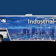
Eaton industrial controls kicked off their 2017 Nationwide Roadshow Tour. The hands-on, 40-foot, interactive showroom will travel to nearly 20 U.S. cities and educate original equipment manufacturers (OEMs), facilities managers, commercial customers, end users, contractors and others about Eatons newest energy efficient innovations for heating, ventilation, air conditioning and refrigeration (HVAC/R), pumping, process industry and machinery applications.The Eaton Industrial Controls Roadshow features four interactive demos arranged by commercial and industrial application environments. Live demo areas include: an Eaton VFD system drive, a multi-pump booster system, a material handling conveyor, and a mixing and separating process. An interactive Internet of Things (IoT) component allows visitors to create their own fault situation and receive alerts on their mobile phones.

The Eaton Industrial Controls Roadshow made its first stop in Las Vegas, Nevada at the 2017 AHR Exposition. The roadshow tour recently left St. Louis, MO and is currently in route its next stop. The roadshow is also planned to visit other select cities including Milwaukee, Wisconsin; and Cleveland, Ohio. The tour will conclude in November with a final visit to Fresno, California. VisitEaton.com/ControlTourto view the full schedule or registerhere.

Eaton industrial controls have been providing power management needs for more than a century. Over the years, Eaton has expanded their expertise and portfolio of products and servicesby uniting some of the worlds most respected names withEatons strong heritage of innovation. The roadshow therefore reflects complete packaged solutions that not only include industrialcontrol products, but also our world-class motor control centersand breakers with Bussmann E series fuses, B-Line E seriessupport systems and switches, and Crouse-Hinds E seriesexplosion-proof enclosures. With customers in 175 countriesand more than 100,000 employees worldwide, Eaton has expertson the ground to develop more complete and customizedsolutions to respond to power management needs.

Eaton is a power management company with 2016 sales of $19.7 billion. Eaton provides energy-efficient solutions that help customers effectively manage electrical, hydraulic and mechanical power more efficiently and safely. Eaton has approximately 95,000 employees and sells products to customers in more than 175 countries.

For Eaton VFD repair or replacement quotes, contact Precision Electric. For more information on Eaton products, visitwww.eaton.com.

DC Motor Surplus Inventory

The Following DC Electric Motors are currently available in our Surplus Inventory. You can call us anytime to request a quote.

Ph: 877-625-2402


OUR Stock NumberManufacturerModel NumberType / Description / Nameplate InformationCondition
116PACIFIC SCIENTIFICSR3624-8291-7-56BC1/4 HP, 1750 RPM, 56C FRAME, 90VDC, TEFC HAS BASENS
173BALDORCDP33161/3 HP, 1750 RPM, 56C FR, 180VDC, PM TENVE OK
174BALDORCDP33301/2 HP, 1750 RPM, 56C FR, 90 VDC, PM, TENVE OK
176PACIFIC SCIENTIFICSR3640-8293-84-7-56HC1/2 HP, 1750 RPM, 56 FR, 90 VDC, PM, TENV, D FLANGEE OK
423GENERAL ELECTRIC6VFM1050B561A11/2 HP, 1725 RPM, 56 FR, 100F, 90A, TENVE OK
425BALDORCDP33261/2 HP, 1750 RPM, 56C FR, 180 VDC, PM, TENVE OK
108BALDORCDP34363/4 HP, 1750 RPM, 56C FRAME, 180 VDC, PM, TEFC, NO BASEE OK
118BALDORCDP35181 HP, 1750 RPM, 56C FRAME, 180 VDC, PM, TEFC, NO BASENS
428LEESONC4D28FK6G1 HP, 2500 RPM, XS56C FR, 180VDC, PM, TEFCE OK
412GENERAL ELECTRIC5BPA56RAG9A1 HP, 1725 RPM, 56 FR, 180 VDC, PM, TEFCE OK
177BALDORCDP34551 HP, 1750 RPM, 56C FR, 180 VDC, PM, TEFCE OK
131RELIANCEDC0189ATCZ2 HP, 1750/1950 RPM, 189ATZ FRAME, 240 A, 150 F, BVE OK
155GENERAL ELECTRIC5CD144VC001B0083 HP, 2500/2750 RPM, 180 A, 200/100 F, 186ATC, TENVE OK
153GENERAL ELECTRIC5CD144VC001B0083 HP, 2500/2750 RPM, 180 A, 200/100 F, 186ATC, TENVE OK
133GENERAL ELECTRIC5CD144VC001B0083 HP, 2500/2750 RPM, 180 A, 200/100 F, 186ATC, TENVE OK
156BALDORCD62033 HP, 1750 RPM, 184TC FR, 180A / 100/200 F, TEFCE OK
157GENERAL ELECTRIC5CD145VC005B0013 HP, 1750/2050 RPM, CD189ATC FR, 180 A/100/200 F, TENVE OK
162RELIANCET18P1118E-7S3 HP, 1750 RPM, DC0189ATY FR, 200F, 180A, DPE OK
624RELIANCET18R1323H-PT5 HP, 1750/2300 RPM, CT811ATZ FR, 500A, 300F, DPNS
432CUTLER HAMMER250-100-0116A5 HP, 1150/2000 RPM, 256AT FR, 500/300 VDC, DPE OK
150CUTLER HAMMER250-100-0116A5 HP, 1150/2000 RPM, 256AT FR, 500/300 VDC, DPE OK
141GENERAL ELECTRIC5CD1531A806A8007.5 HP, 2500/2875 RPM, 500 A, 150/300 F, CD219T FR, BVE OK
142MAGNETEK2190B411L027.5 HP, 1750 RPM, 180 A, 200 F, 219AT FRAME, BVE OK
434BALDORD501010 HP, 1750 RPM, AD219AT FR, 500A, 150/300F, DPFGE OK
130RELIANCE11839122T2115 HP, 1250/3750 RPM, 259AT FRAME, 120 A, 240 F, BVE OK
137GENERAL ELECTRIC5CD063KA038A12715 HP, 1750/2300 RPM, CD258AT FR, 500 A, 150/300 F, BVE OK
433BALDORD2018R15 HP, 1750/2300 RPM, SC2113ATZ FR, 240A, 180F, DPNS
129RELIANCE4LA843818TL20 HP, 1750 RPM, 284T FRAME, 120 A, 240 F, BVE OK
146RELIANCE06KA867603-ZU20 HP, 1750/1950 RPM, LC2512ATZ FR, 500/300 VDC,E OK
147RELIANCEF28P1701A25 HP, 2500/3000 RPM, 284AT FR, 240/240 VDC, BVE OK
436RELIANCER-66575-T1-HS30 HP, 500/2000 RPM, 505-AS FR, 240A, 240F, HAS BLOWERE OK
441CMC2890B452C0140 HP, 1750 RPM, 289ATZ FR, 500A, 300F, DPRG
454RELIANCET28S1330E-AC60 HP, 1750/2100 , MC2812ATZ, 300/500 VDC, DPBVRG
152POWERTECA28DLF100090001175 HP, 2500 RPM, 2810TZ FR, 640 BUS VDC, BRUSHLESSE OK
440RELIANCE1U827783T5-LP100 HP, 1750 RPM, 503A FR, 480A, 240F, FORCE COOLEDE OK
Yaskawa Servo Motor Repair

Yaskawa Servo Motor Repair

Yaskawaservo motor repair is less expensive than Yaskawa servo motor replacement. Only trained technicians should perform Yaskawa servo motor repair. Trained technicians undergo unique testing procedures on Yaskawa servo motors that are dependent to eachservo motors’ model, features, operations, and prints. Trained technicians will have the ability to perform these procedures successfully and safely. The first step of Yaskawa servo motor repair is the inspection of equipment for cosmetic damage or missing parts. Trained technicians take this step to ensure a successful repair is possible before proceeding further. Taking digital photos of the servo motor prior to further processing is also suggested.

Servo Motor nameplate data and preventative maintenance info should be collected by the technician and safely stored for future reference. Once these initial steps are complete, the servo motor should be meter tested before test running on a control panel; Meter testing prevents further damage to parts, motor winding, and insulation. The servo motor should then beconnected to a test panel to check EMF (electromagnetic frequency), encoder or resolver feedback, and commutation alignment; These standard tests are to ensure functionality, oncethe motor is installed forproduction. Servo motors also need to be tested with an oscilloscope to create an operation print. Once an operation printout is generated, a technicianwill check for connection issues, magnet failure, and winding failure. Once this is complete, the trained technician will perform a 100% component test to the servo motor. Once these tests are finished, the cost to repair and replace parts is estimated and labor is also determined. If the cost to repair the servo motor exceeds 50-60% of the cost to replace, the customer is offered a replacement quote. Otherwise, the technician can create a repairquote with lead time and communicate all pertinent information to the customer. Once the customer approves the repair quote, the technician will proceed with the repair.

Now, the technician will have an in-house machinist perform shaft and bearing housing repairs that are damaged. Old bearings are removed and saved for future reference. The technician will clean up and make repairs to all other damaged parts; replacement parts that cannot be repaired are ordered at this time. Finally, the technician will install new bearings and reassemble the servo motor for final testing. During the final test procedure, technicians should connect the motor to an inverter,with and without a load. Running the servo motor on an inverterensures complete functionality; Running the servo motor with a load will ensure full functionality once it is running in production. Testing with an inverter also allows verification that the servo can operate at full voltage and withstand full load amps of motor specifications. Yaskawa servo motor repair shops should work closely with all servo motor manufacturers. Working closely with servo motor manufacturers allows repair shops accessibility to servo motor data sheets, parts, and other valuableinformation. Repair technicians use data sheets to ensure that the servo motor performs equal to orbetter than, the original manufacturer standards.

Most Yaskawa servo motor repair shops offering servo motor repair don’t perform the repair themselves. These repair shops actually outsource the repair to a third party and then mark up the repair price to their customer. Outsourcing the servo motor repair is not a good idea. Outsourcing the repair is done when the repair shop does not have the ability or training to perform the servo motor repair. Repair shops use third party repair shops such as Precision Electric, because Precision Electric has been in the manufacturing industry since 1984 and their competent staff have the skills and training needed to perform these services. Most customers don’t find out that their repair shop is outsourcing the repair to Precision Electric until they contact the repair center asking technical questions. When this happens, the repair center is unable to communicate or provide technical information to the customer; and the repair center has their customer call Precision Electric for the answers they need.

This process ends up costing the manufacturer more money, time, and additional problems with their equipment. Manufacturers and other servo motor users should send their Yaskawa servo motor to the company that is actually performing the repair. This will save money, time and this will ensure a professional and high quality repair. Yaskawa servo motor repair from Precision Electric is performed in house and includes a 12 month in-service warranty. For Yaskawaservo motor repair and replacement quotes, contactPrecision Electric at 574-256-1000. Or, initiate your servo motor repair here and send it to Precision Electric today.

Robotic Automation: ABB Robots For The Packaging Industry

Robotic Automation: ABB Robots For The Packaging Industry

ABB robotic automation ensures shorter product life cycles, new packaging designs, product variants and batch manufacturing. Compared to dedicated hard automation, robot lines are shorter and allow far better utilization of floor space. In addition to increased up-time and total throughput of production, fewer accidents and increasingly demanding workplace laws are compelling reasons to make the transition to ABB robotic automation. Robots are usually associated with handling repetitive tasks in a process either in high volume production roles or where flexible handling systems are needed for frequent changes. In the packaging industry, robots generally fall into three main areas:


  • Pick and Place Applications (where products are packed into trays or secondary packages)
  • Feed Placement (where products are prearranged on a conveyor to ease future packaging procedures)
  • Palletizing (pallet loading and unloading)


Picking

This is an area in which ABB services a multitude of products, applications and packaging line set-ups. Frozen food, bakery and confectionery, ice cream, meat and fish, cheese, pet food, medical products, shampoo and perfume bottles are a few examples. The ABB IRB 360 is the first 2nd generation delta robot; The FlexPickerTM . The new robot family will initially see three models available. Stainless steel versions are available for wash down duties such as in meat and dairy handling applications. Apart from even greater performance, the new delta robot has a significantly increased payload of up to 3 kg opening up further application possibilities, especially at the end of line. For full 6-axis flexibility, less demanding cycle times and payloads of up to 5 kg, ABB recommends the IRB 140.

Palletizing

Placing boxes, trays, bags, bottles or other items on a pallet seems easy enough. But, when youre dealing with the rigorous demands of multiple feeder lines, quick box-pattern changes and high up-time, nothing compares to ABB robotic automation. The ABB IRB 660 has the versatility, reach and handling capacity needed for most palletizing applications. For even greater payload requirements, ABB standard 6-axis robots are the largest and are built to handle as much as 1,433 lbs.

The IRB 660 is a refinement of the well established, proven, ABB IRB 640 palletizer, with more than 1,800 installations worldwide. The new version of this robot blends speed, reach and payload like no other. Exceptionally fast, this 4-axis performer combines a 3.15 meter reach with a 250 kg payload, making it ideal for palletizing bags, boxes, crates, bottles and more. The new palletizer comes in two versions; a high throughput version designed for 250 kg and a high-speed version built to handle 180 kg payloads at full speed. The IRB 660 has the versatility, reach and handling capacity to meet the demands of just about any palletizing application. And its robust enough to perform steadily in the toughest environments.

Tailor Made Robots For Demanding Packaging Industries

ABB robotic automation includes specialized robots for picking, packing and palletizing. In addition, ABB provides a wide range of standard 6-axis robots which allows customers to meet the demands of nearly all applications in the packaging industry. Whats more, ABBs unique packaging software, including vision technology and conveyor tracking, facilitates continuous production flows and packing on-the-fly. This allows for efficient handling of food and beverages, pharmaceuticals, cosmetics, electronics or personal care products.

High Speed Packing

The ABB FlexPicker IRB 360 is a unique parallel-arm robot designed for the most exacting high-speed picking and packing applications. The new robot succeeds ABBs widely used FlexPickerTM IRB 340 system and is the result of 10 years experience and research and development combined with proven packaging technology. ABB has over 2000 delta robots installed globally and is the leader in this state of the art picking and packing technology. The newest version of the IRB 340 is called the FlexPickerTM IRB 360.

Cost Efficient Packing

The 4-axis IRB 260 houses all the necessary features for placing items in boxes, tray handling and more. Optimized for packing applications this robot can work closely to its own base, allowing very compact packing cells and integration into tight packing machines. IRB 260

features a 30 kg payload capacity and short cycle times to meet the packing industry requirements. Like all ABB robots, the IRB 260 is compatible with PickMaster, our dedicated software for packaging applications, including vision guidance and easy programming.

Food Safety & Pharmaceutical

ABB builds robots to meet the most demanding work conditions as well as the highest hygiene standards. In addition, all ABB robots are IP67 certified, ensuring tightly sealed joints and connectors. The IRB 360, which is most likely to handle open food, is available in wash-down and stainless steel and is IP69K certified.

The demands on quality validation and traceability are extremely high in pharmaceutical production. The absolute accuracy, repeatability and high up-time of ABB robots result in massive improvements over manual operation or dedicated production equipment. All ABB smaller robots are suited to primary packing and are verified for clean-room operation.

To learn more about ABB Robotic Automation, visit the ABB Website. For ABB robot integration or replacement quotes, contact Precision Electric. Precision Electric can retrofit obsolete packaging machines / inefficient packaging systems with ABB Robotic Technology. We also offer servo drive repair and servo motor repair for All industrial robots.

 

fanuc-servo-motor-repair-3

Fanuc Servo Motor Repair, Short Summary Of Our Procedure

Fanucservo motor repair is less expensive than Fanuc servo motor replacement. Only trained technicians should perform Fanuc servo motor repair. Trained technicians undergo unique testing procedures on Fanuc servo motors that are dependent to eachservo motors’ model, features, operations, and prints. Trained technicians will have the ability to perform these procedures successfully. The first step of Fanucservo motor repair is the inspection of equipment for cosmetic damage or missing parts. Trained technicians take this step to ensure a successful repair is possible before proceeding further. Taking digital photos of the servo motor prior to further processing is also suggested.

Servo Motor nameplate data and preventative maintenance info should be collected by the technician and safely stored for future reference. Once these initial steps are complete, the servo motor should be meter tested before test running on a control panel; Meter testing prevents further damage to parts, motor winding, and insulation. The servo motor should then beconnected to a test stand to check EMF (electromagnetic frequency), encoder or resolver feedback, and commutation alignment; These standard tests are to ensure functionality oncethe motor is installed forproduction. Servo motors also need to be tested with an oscilloscope to create an operation print. Once an operation printout is generated, a technicianwill check for connection issues, magnet failure, and winding failure. Once this is complete, the trained technician will perform a 100% component test to the servo motor.

Once these steps are complete, the technician will make repairs to applicable parts and order replacement parts that cannot be repaired. Finally, the technician will reassemble the servo motor for final testing. During the final test procedure, technicians should connect the motor to an inverter,with and without a load. Running the servo motor on an inverterensures complete functionality. Testing with an inverter also allows verification that the servo can operate at full voltage and withstand full load amps of motor specifications. Repair shops should work closely with all servo motor manufacturers. Working closely with servo motor manufacturers allows repair shops accessibility to servo motor data sheets, parts, and other valuableinformation. Repair technicians use data sheets to ensure that the servo motor performs equal to, orbetter than, the original manufacturer standards.

Most repair shops offering Fanucservo motor repair do not even perform the repair in their facility. Instead, these repair shops outsource the repair to a third party such as Precision Electric. Most manufacturers don’t know that their repair center isn’t even performing the repair. This process ends up costing the manufacturer more money, time, and additional problems with their equipment. The best option for manufacturers is to send their Fanuc servo motor to the company that’s actually performing the repair. This will save the manufacturer money, time and ensure the best possible repair.Fanucservo motor repair from Precision Electric is performed in house and includes a 12 month in-service warranty. For Fanucservo motor repair and replacement quotes, contactPrecision Electric at 574-256-1000