 https://www.precision-elec.com/wp-content/uploads/2025/09/lenze-ac-tech-i550-protec-decentralized-vfd-solution.png
1024
1024
Craig Chamberlin
https://www.precision-elec.com/wp-content/uploads/2025/02/Precision-Electric-Logo-TEXT-ONLY-Color-NEW.png
Craig Chamberlin2025-12-15 09:01:002025-09-26 16:54:25Lenze Ac Tech I550 Protec Variable Frequency Drives Vfds: Le
https://www.precision-elec.com/wp-content/uploads/2025/09/lenze-ac-tech-i550-protec-decentralized-vfd-solution.png
1024
1024
Craig Chamberlin
https://www.precision-elec.com/wp-content/uploads/2025/02/Precision-Electric-Logo-TEXT-ONLY-Color-NEW.png
Craig Chamberlin2025-12-15 09:01:002025-09-26 16:54:25Lenze Ac Tech I550 Protec Variable Frequency Drives Vfds: Le https://www.precision-elec.com/wp-content/uploads/2025/09/american-rotary-ad-rotary-phase-converters-workshop-installation.png
1024
1024
Craig Chamberlin
https://www.precision-elec.com/wp-content/uploads/2025/02/Precision-Electric-Logo-TEXT-ONLY-Color-NEW.png
Craig Chamberlin2025-12-15 09:01:002025-09-26 16:13:36Guide to American Rotary AD Rotary Phase Converters
https://www.precision-elec.com/wp-content/uploads/2025/09/american-rotary-ad-rotary-phase-converters-workshop-installation.png
1024
1024
Craig Chamberlin
https://www.precision-elec.com/wp-content/uploads/2025/02/Precision-Electric-Logo-TEXT-ONLY-Color-NEW.png
Craig Chamberlin2025-12-15 09:01:002025-09-26 16:13:36Guide to American Rotary AD Rotary Phase Converters https://www.precision-elec.com/wp-content/uploads/2025/09/american-rotary-adx-phase-converter-3-phase-power-solution.png
1024
1024
Craig Chamberlin
https://www.precision-elec.com/wp-content/uploads/2025/02/Precision-Electric-Logo-TEXT-ONLY-Color-NEW.png
Craig Chamberlin2025-12-15 09:01:002025-09-26 16:25:15American Rotary ADX Rotary Phase Converters Explained
https://www.precision-elec.com/wp-content/uploads/2025/09/american-rotary-adx-phase-converter-3-phase-power-solution.png
1024
1024
Craig Chamberlin
https://www.precision-elec.com/wp-content/uploads/2025/02/Precision-Electric-Logo-TEXT-ONLY-Color-NEW.png
Craig Chamberlin2025-12-15 09:01:002025-09-26 16:25:15American Rotary ADX Rotary Phase Converters Explained https://www.precision-elec.com/wp-content/uploads/2025/09/precision-electric-boost-phase-rotary-phase-converter.png
1024
1024
Craig Chamberlin
https://www.precision-elec.com/wp-content/uploads/2025/02/Precision-Electric-Logo-TEXT-ONLY-Color-NEW.png
Craig Chamberlin2025-12-15 09:01:002025-09-26 16:36:16Precision Electric Boost-Phase Rotary Phase Converters Guide
https://www.precision-elec.com/wp-content/uploads/2025/09/precision-electric-boost-phase-rotary-phase-converter.png
1024
1024
Craig Chamberlin
https://www.precision-elec.com/wp-content/uploads/2025/02/Precision-Electric-Logo-TEXT-ONLY-Color-NEW.png
Craig Chamberlin2025-12-15 09:01:002025-09-26 16:36:16Precision Electric Boost-Phase Rotary Phase Converters Guide https://www.precision-elec.com/wp-content/uploads/2025/09/precision-electric-pro-phase-rotary-phase-converters-overview.png
1024
1024
Craig Chamberlin
https://www.precision-elec.com/wp-content/uploads/2025/02/Precision-Electric-Logo-TEXT-ONLY-Color-NEW.png
Craig Chamberlin2025-12-15 09:01:002025-09-26 16:45:14Precision Electric Pro-Phase Rotary Phase Converters Guide
https://www.precision-elec.com/wp-content/uploads/2025/09/precision-electric-pro-phase-rotary-phase-converters-overview.png
1024
1024
Craig Chamberlin
https://www.precision-elec.com/wp-content/uploads/2025/02/Precision-Electric-Logo-TEXT-ONLY-Color-NEW.png
Craig Chamberlin2025-12-15 09:01:002025-09-26 16:45:14Precision Electric Pro-Phase Rotary Phase Converters Guide https://www.precision-elec.com/wp-content/uploads/2025/09/kay-industries-rotary-phase-converters-workshop-3-phase-power.png
1024
1024
Craig Chamberlin
https://www.precision-elec.com/wp-content/uploads/2025/02/Precision-Electric-Logo-TEXT-ONLY-Color-NEW.png
Craig Chamberlin2025-12-15 09:01:002025-09-26 17:04:40Kay Industries Rotary Phase Converters: Engineer’s Guide
https://www.precision-elec.com/wp-content/uploads/2025/09/kay-industries-rotary-phase-converters-workshop-3-phase-power.png
1024
1024
Craig Chamberlin
https://www.precision-elec.com/wp-content/uploads/2025/02/Precision-Electric-Logo-TEXT-ONLY-Color-NEW.png
Craig Chamberlin2025-12-15 09:01:002025-09-26 17:04:40Kay Industries Rotary Phase Converters: Engineer’s Guide https://www.precision-elec.com/wp-content/uploads/2025/09/kay-industries-ma-rotary-phase-converters-installation.png
1024
1024
Craig Chamberlin
https://www.precision-elec.com/wp-content/uploads/2025/02/Precision-Electric-Logo-TEXT-ONLY-Color-NEW.png
Craig Chamberlin2025-12-15 09:01:002025-09-26 17:18:34Kay Industries MA Rotary Phase Converters: Buyer’s Guide
https://www.precision-elec.com/wp-content/uploads/2025/09/kay-industries-ma-rotary-phase-converters-installation.png
1024
1024
Craig Chamberlin
https://www.precision-elec.com/wp-content/uploads/2025/02/Precision-Electric-Logo-TEXT-ONLY-Color-NEW.png
Craig Chamberlin2025-12-15 09:01:002025-09-26 17:18:34Kay Industries MA Rotary Phase Converters: Buyer’s Guide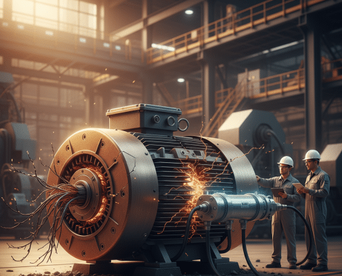 https://www.precision-elec.com/wp-content/uploads/2025/09/vfd-motor-failure-tci-msd-sine-wave-filters.png
1024
1024
Craig Chamberlin
https://www.precision-elec.com/wp-content/uploads/2025/02/Precision-Electric-Logo-TEXT-ONLY-Color-NEW.png
Craig Chamberlin2025-12-14 09:01:002025-09-25 14:46:02TCI MSD Sine Wave Filters: Prevent VFD Motor Failure
https://www.precision-elec.com/wp-content/uploads/2025/09/vfd-motor-failure-tci-msd-sine-wave-filters.png
1024
1024
Craig Chamberlin
https://www.precision-elec.com/wp-content/uploads/2025/02/Precision-Electric-Logo-TEXT-ONLY-Color-NEW.png
Craig Chamberlin2025-12-14 09:01:002025-09-25 14:46:02TCI MSD Sine Wave Filters: Prevent VFD Motor Failure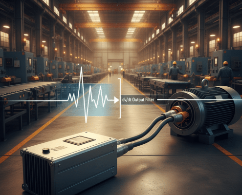 https://www.precision-elec.com/wp-content/uploads/2025/09/vfd-motor-damage-tci-v1k-dv-dt-output-filter.png
1024
1024
Craig Chamberlin
https://www.precision-elec.com/wp-content/uploads/2025/02/Precision-Electric-Logo-TEXT-ONLY-Color-NEW.png
Craig Chamberlin2025-12-13 09:01:002025-09-25 14:41:46TCI V1K Motor Protection Filter DV-DT Output Filter
https://www.precision-elec.com/wp-content/uploads/2025/09/vfd-motor-damage-tci-v1k-dv-dt-output-filter.png
1024
1024
Craig Chamberlin
https://www.precision-elec.com/wp-content/uploads/2025/02/Precision-Electric-Logo-TEXT-ONLY-Color-NEW.png
Craig Chamberlin2025-12-13 09:01:002025-09-25 14:41:46TCI V1K Motor Protection Filter DV-DT Output Filter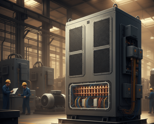 https://www.precision-elec.com/wp-content/uploads/2025/09/tci-hsd-passive-harmonic-filters-industrial-application.png
1024
1024
Craig Chamberlin
https://www.precision-elec.com/wp-content/uploads/2025/02/Precision-Electric-Logo-TEXT-ONLY-Color-NEW.png
Craig Chamberlin2025-12-12 09:01:002025-09-25 14:33:20TCI HSD Passive Harmonic Filters: A Complete VFD Guide
https://www.precision-elec.com/wp-content/uploads/2025/09/tci-hsd-passive-harmonic-filters-industrial-application.png
1024
1024
Craig Chamberlin
https://www.precision-elec.com/wp-content/uploads/2025/02/Precision-Electric-Logo-TEXT-ONLY-Color-NEW.png
Craig Chamberlin2025-12-12 09:01:002025-09-25 14:33:20TCI HSD Passive Harmonic Filters: A Complete VFD Guide https://www.precision-elec.com/wp-content/uploads/2025/09/tci-kmg-sine-wave-filter-product-image.png
1024
1024
Craig Chamberlin
https://www.precision-elec.com/wp-content/uploads/2025/02/Precision-Electric-Logo-TEXT-ONLY-Color-NEW.png
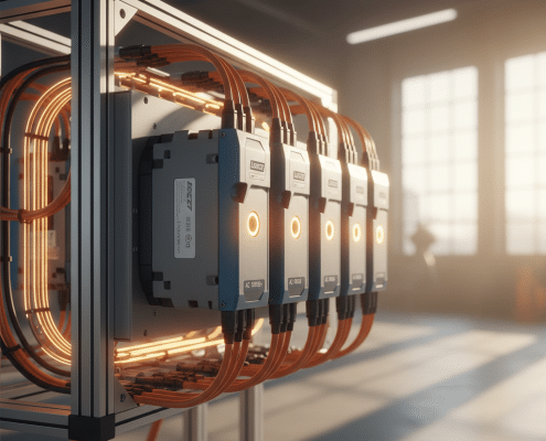
Craig Chamberlin2025-12-11 09:01:002025-09-25 14:35:01TCI KMG Sine Wave Filters: A Guide to Motor Protection
https://www.precision-elec.com/wp-content/uploads/2025/09/tci-kmg-sine-wave-filter-product-image.png
1024
1024
Craig Chamberlin
https://www.precision-elec.com/wp-content/uploads/2025/02/Precision-Electric-Logo-TEXT-ONLY-Color-NEW.png
Craig Chamberlin2025-12-11 09:01:002025-09-25 14:35:01TCI KMG Sine Wave Filters: A Guide to Motor Protection https://www.precision-elec.com/wp-content/uploads/2025/09/tci-pf-guard-harmonic-filters-explained.png
1024
1024
Craig Chamberlin
https://www.precision-elec.com/wp-content/uploads/2025/02/Precision-Electric-Logo-TEXT-ONLY-Color-NEW.png
Craig Chamberlin2025-12-10 09:01:002025-09-25 14:27:13TCI PF Guard Harmonic Filters: The Ultimate Guide
https://www.precision-elec.com/wp-content/uploads/2025/09/tci-pf-guard-harmonic-filters-explained.png
1024
1024
Craig Chamberlin
https://www.precision-elec.com/wp-content/uploads/2025/02/Precision-Electric-Logo-TEXT-ONLY-Color-NEW.png
Craig Chamberlin2025-12-10 09:01:002025-09-25 14:27:13TCI PF Guard Harmonic Filters: The Ultimate Guide


