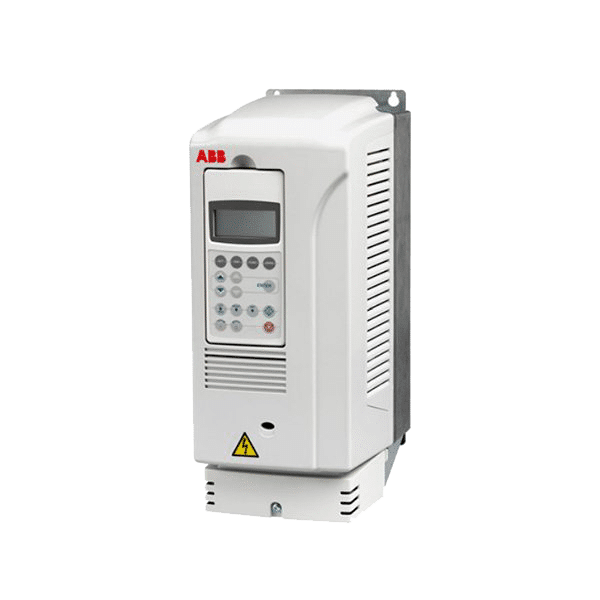
ABB ACS355 Training Lesson 1: Basic Input Voltage & Motor Wiring – Variable Frequency Drives
About This Video
This video covers wiring the input and output sections of the ABB ACS355 Variable Frequency Drive. The input voltage will be wired as either single phase or three phase and the output voltage is designed to be wired to AC motors only. It’s also extremely important to note that you should not wire any devices or contactors between the output of the ACS355 variable frequency drive and the motor, this can result in damaging the motor.
Video Transcript
Hello everyone, my name is Craig Chamberlin with Precision Electric at precision-elec.com. We are your industrial automation service center, drives, motors, PLCs, controls; weve done it for about 30 years, so if you have any questions, feel free to call us and we will take care of ya.
Todays video is gonna cover the ACS355 variable frequency drive, basically the first start up. We are going to be powering it up with the input voltage and we are going to be wiring the motor as well and there are some considerations you need to take uh when making sure you are wire it properly as far as wire size is concerned and fuse sizing uh that actually arent in the manual. So there are some recommendations I am going to give you that arent in the actual manual. But if you do want to follow along in the manual, we are in the section for Connecting the Power Cables and once weve got everything connected, we are going to power it up and look at what weve got. So lets go ahead and get started.
Now to get started, the first thing we are going to do is wire our input voltage. Now here I had my fuses, or my fuse block, set up for my two hot wires that are coming in. The reason I have two hotwires is because I actually have single phase 220 volt which gives me two hot black wires that need to be fused. Now for this particular set up, my fusing size is based on my input current of my drive. If I look on the side of my drive, I can actually tell on the nameplate that my input current is 6.1 amps. In general when youre sizing a fuse, you go 1.5x your input current, so in my instance Im using two 10 amp fuses. You can also use a circuit breaker if you wish. So depending on the current input of your drive, thats going to determine what your fuse sizing is.
Now when I bring my input voltage here through the bottom, I go through the fuses and I come out on the top, and I come down back up into the input section of the drive, and here on mine, since its single phase, I have L N and W1. W1 doesnt have anything wired to it because, again, I have only two hot wires right here, coming in on single phase, and I wire those two hot wires to L and N or U1 and V1 and thats my wiring for my input voltage for my drive.
Now once the input voltage is wired, I can go ahead and apply power to the drive by pushing in the fuses, in my instance, and then you see the screen come on. So that basically tells me my input voltage is wired correctly and Ive got my drive powered up.
Now if I want to shut it down again, which Im going to real quick, I can pull those fuses out, or if youre using a circuit breaker, you can just open the circuit breaker and then after a couple seconds, its actually gonna turn the screen off.
Now for the output section of the drive, its important for me to note I have a 3 phase motor and all the ACS355 drives use 3 phase motors. So in this instance, Im going to be wiring the output to, its actually labeled here on the drive, motor, but I have a U2, V2, and W2 and those particular terminals are for each phase of the motor and they can be wired in any order that you wish, just know itll determine the direction of your motor depending on which way you wire it, so if, for some reason, it starts off in the wrong direction you can just swap out one of these phases and itll actually make it go in the other direction. So what Im doing is, U2 V2 W2, they come out, and for me they just go into a terminal block, and that terminal block comes out into my motor. So that makes sure everything is wired correctly on the motor side.
Now the only thing I have left to mention is the ground wires because you want to make sure both your line side and motor are both grounded. At the bottom of the the drive there is a little ground section, there actually is a little label there called PE, and there’s another little ground signal and you wire your grounds and you tie them together directly to this. DO not wire your neutral to it, your neutral comes into N, so if you a single phase input and a neutral, thats gonna go to N thats not gonna go to your ground. And thats pretty much all there is to it.
As I said before, you can pop on the power, drive turns on, and everything is working good. We havent run the motor yet, but in the next video, we are gonna cover how to start it up and run the motor and that part will be pretty easy. Thats one of the nice thing about these drives, they are very user friendly.
So one other thing I kinda do want to point out, and let me determine the best course to say this, but for the input voltage here, for your fusing, you want to make sure you reference a manual when youre actually doing your wire sizes. So what I have here is our manual, the ABB manual that came with the drive, doesnt have fuse sizing, uh Im sorry, recommended wire sizing. So you want to look into the EASA electrical handbook, or electrical engineering handbook, you can find these online. There is a section for allowable ampacities of not more than 3 insulated conductors, in my particular EASA manual its on page 74, but depending on the type of wire youre using, this will tell you, based on your current, so in my case 6amps, what wire size I can use. Obviously you can always use large, but in my case I can use wire as small as 18 amps because I am using THHN wire. So I just wanted to reference that for you guys who are wondering what wire sizes to use because I get that question quite a bit and thatll help you determine that because its not actually in the manual.
So that all there is to this video, again my name is Craig Chamberlin with Precision Electric, dont forget to visit our website at precision-elec.com, where you can purchase these drives and essentially this is all you need to do to wire your voltage or input voltage and your motor to the drive. Now when you first start it up, there is a start up assistant that is covered in this manual, you’ll go through the basic parameters and pretty quickly once you get through that, you can press the start up button and your motor will start. So again thank you for stopping by, if you have any questions we are your industrial automation service center, drive, motor, PLCs, controls weve been doing them for about 30 years so anything you need help with, wed be more than happy to take care of ya, so talk to you then!
