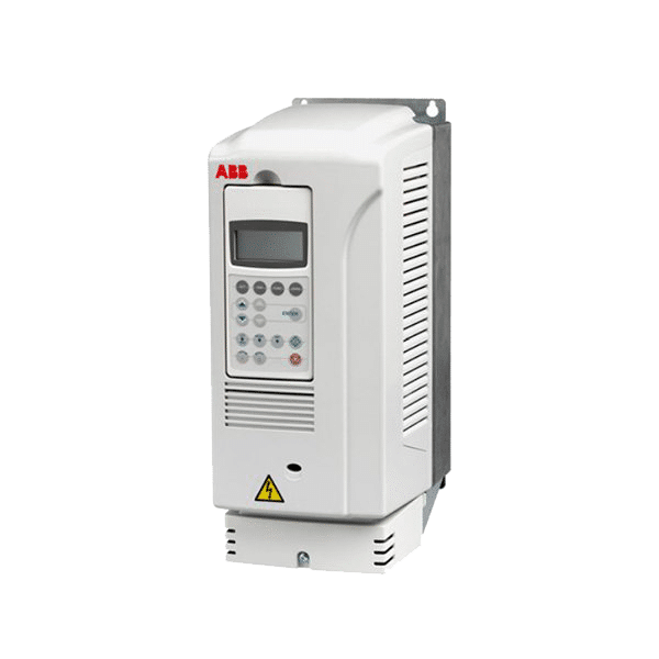
ABB ACS355 Training Lesson 4: Basic Start Stop Pushbutton Control Wiring & Programming – VFDs
About This Video
This video will cover the complete wiring and parameter programming setup of a start, stop pushbutton control panel on the ABB ACS355 variable frequency drive. This process is quite simple and it offers a great option for people who are interested in using a speed start and stop pushbuttons for controlling their drive instead of the standard keypad.
Video Transcript
Hello everyone, my name is Craig Chamberlain with Precision Electric at precision-elec com. We are your industrial automation service center, drives, motors, controls, automation, PLC’s. You name it we’ve done it for over 30 years if you have any questions we sell these products online and we also are more than willing to help you. So if you look, free to give us a call.
Today’s video is going to continue the series on the ACS 355 variable frequency drive, and we’re going to be covering how to start the drive from a push-button panel. This is actually just a basic two-button start/stop control and it only requires three wires. We’re going to have a common – or Im sorry – a plus voltage coming into the start button and then the other side of the start button is going to come into the drive. And then we have a plus voltage coming into the stop button. And the other side of the stop button which is a normally closed is going into a second input on the drive and then we need to make a slight programming change. And after we make that programming change the drive will be ready to accept those inputs and we will be good to go. So let’s go ahead and get it wired and programmed and go from there.
Now the first part of this video is going to cover the programming change and we just have to change one value – that’s the macro – because in the previous videos we set up the ABB standard macro. Now I still recommend you go in and check out that video for studying up the standard macro because it also has you set up your motor data, but in this case, we’re changing the macro so that it’ll actually match a three-wire start/stop control. So this print on page 111, of the manual – the three wire macro – is actually the one we’re going to be switching to because this will allow us to set up our push buttons appropriately for our start/stop control. So let’s go ahead and go into the menu – so we’re going to press the menu button – and we’re going to go to the parameters option and then we’re going to scroll down to startup data which is parameter group 99 and we’re going to click select, and we’re going to scroll down to parameter 9902 which is the application macro. As I said before, right now it’s set up for the ABB standard we’re going to click Edit, and we’re going to switch that macro to 3 wire now what that does is it changes the wiring print for this drive.
It’s kind of nice actually, these drives have a series of macros that are like presets that are set up for already existing configurations so you can find the one that actually best fits your application, and go in here and change it at any time. So we’re going to change this one to 3 wire and we’re to click Save, and it goes ahead and changes it. It says 3 wire on the screen and we’re going to exit out.
Now that we’ve actually changed our three wires start our application macro now we can actually go in and do our wiring. Now, according to our print our common of our push buttons, in other words the supply voltage of our push buttons, we’re going to come from parameter, I’m sorry, terminal 9 and this is going to come in to one side of our start button and then the other side of our start button is coming out into terminal 12. So essentially, electricity is going to flow from terminal 9 into terminal 12 when we press that button because the buttons are normally open push button. So as soon as we press the button in electricity will flow from 9 to 12 and the start command will be issued.
Terminal 13 is our stop. Now the way stop buttons work is that they’re normally closed. The reason being is if for some reason the button fails or falls apart on behind it – that’s happened, believe it or not, the drive will always be stopped. So electricity is always flowing to terminal 13 or our stop command unless you press the button. When you press the button you actually interrupt the electrical flow and stop the drive. So the drive always needs some kind of input on 13 in order to run in this configuration. So we’re going to again have our terminal 9 electricity flow in to the north – one side of our normally closed on our stop button and on the other side of our normally closed our stop button we’re coming back into terminal 13 and electricity will always be flowing between those two, unless I press the stop button and then the drive knows a stop command has been issued.
And that is all there is to wiring and programming it so let’s go ahead and run it. Ok so now that we have it programmed, essentially right now I’m in local control, Now in the previous video we covered the local remote, essentially when it’s in local it’s controlling my speed and my start/stop come in from the keypad. So if I press start from the keypad, or stop from the keypad, I can start it locally. Now to switch over to my actual push- button station and my speed pot which I set up and in the previous video, I have to select this local remote button again. And now it’s looking at my wiring in order to determine whether I’m going to start or not. Now I’m going to press the start command. Now in the previous video, we covered that you can basically with a speed pot you can adjust your speed all the way up and all the way down. Now you’ll notice when I press the start button, this drive actually started up right away.
Now there are instances since I just changed our application macro, there are instances where the actual drive will initiate what’s called an ID magnetization run, which means your drive will make some funny noises, and your motor will make some funny noises for about 30 seconds, while the drive identifies the actual characteristics of the motor. So don’t be surprised if the first time you press the start button that happens so I just wanted to point that out that essentially, sometimes, it’s going to actually run especially if it’s the first time running the motor it’s actually going to run a tuning before issuing the start command. So as you can see, my start button worked. As soon as I press this button down electricity flows between Terminal nine and Terminal 12 which is my start command, and right now electricity is always flowing between 9 and 13, and when I press this button it drops out that signal. And when it drops out that signal, the drive detects a stop.
And that is all there is to this video. If you have any other questions, make sure you swing by our website at precision-elec.com. You can also call us, and we do sell these drives at our website so you can get pricing information manuals, any other information you might need in order to kind of get running. And again, if you run into any problems, don’t hesitate to call us. We’ve been doing this for a long time. We’re an industrial automation service center, drives, motors, PLCs, these controls. So feel free to stop by and say hi.
