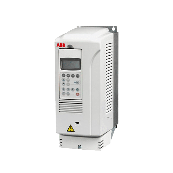
ABB ACS355 Training Lesson 6: Advanced Drive Protective Fuse Sizing & Motor Overload Setup – VFDs
About This Video
This video will cover the complete instructions on the necessity of fuse or circuit breaker protection for your ABB ACS355 variable frequency drive. Protecting your Variable Frequency Drive (VFD) with fuses and breakers are an essential step in making sure you do not damage your drive. This video also covers how to setup your Motor Overload in the drive to properly protect the motor. Make sure to adhere to local laws and recommended wire sizing when performing this setup.
Video Transcript
Hello everyone this is Craig Chamberlain with Precision Electric at precision-elec.com, your industrial motor controls automation service center we’ve been doing this for about 30 years so we’ve been doing it for quite some time if you have any questions don’t hesitate to call.
Today we’re going to continue in our series for the ACS 355 variable frequency drive. We’re going to be talking about protective fusing and protecting your motor.
Fusing protects the input of your drive whether there’s an overloadsituation from the motor, maybe it’s pulling way too much current, maybe had a dead short on the output or a power surge of some kind, fusing is there to protect the input part of your drive.
So we’re going to go over how to size the fusing and of course wire the fusing, and then after that we’re also going to cover how to set the motor overload. The motor overload essentially monitors the current of the motor and if the amount of current being drawn into the motor exceeds what the motor was designed for, the drive makes an attempt to protect the motor and trip out on a motor over current
So we’re going to be setting that up in the parameters. Now for the fusing, we’re going to go ahead and start on the input side. I am going to look in the manual, and we always recommend you guys look through the manual that comes with the drive. It comes with a nice manual actually. On page 51 of my manual at this moment in time, it may change from revision, there is a input wiring section that shows that each hot wire that comes into your drive that’s wired on u, v, and w – that’s u1, v1, w1 actually needs to be fused.
So in my case, I had two hot wires coming into my drive, which is right here from my power source, and those two hot wires that are coming in I put fuses on I have a fuse block here.
Then it comes out from the fuse block into U 1 and V 1. Notice I don’t have anything on W 1 that’s because this is a single-phase drive, not a three-phase. If you had a three-phase drive then you would have three fuses that were actually protecting the drive.
Now, in order to size the fusing on this drive, you want to look on the nameplate on the side of this. In my case, this is a 6.1 amp input drive. The input current is going to be a lot higher on a single-phase drive than the output current. So you take that input current 6.1 you multiply by 1 and a half which is roughly around 9 amps maybe nine and a half amps, and that gives you your fuse sizing.
So in this case, I have 10 amp fuses that are set up for my drive. So I’m protected with 150% of my potential input current. So the sizes are always larger – the fuses are always larger – than the actual current draw of the motor and that’s just a design for overcurrent. As for types of fuses, you can obviously use a circuit breaker. That’s our least recommended option because circuitbreakers tend to have a delay over the longest delay between tripping so you have most likely a situation to damage the drive because that time frame it takes for it to sense the current and then trip is a lot longer than a fuse.
The type of fuses we recommend are a little more expensive are fast-acting current-limiting fuses. And essentially those are designed to blow within milliseconds of exceeding the rated current. A lot of people don’t realize that they don’t take that extra step to get the fast-acting current limiting. We basically tell people it’s cheap insurance, you know what I mean? You buy a five, six hundred dollar drive, or maybe even a five ten thousand dollar drive you know for maybe 5% of the cost of the drive if you can protect the input section without any concerns. It makes a huge difference.
We’ve had a lot of customers in the field, well go out and we’ll find out that that’s the reason they had a circuit breaker and just took too long to trip blew up the not only the breaker but it also blew up the input section of the drive.
So let’s go ahead and go into the programming here, and I will show you how to set up the motor overload. As I said, my input voltage is coming into the actual fuse block here and then the fuse wiring comes out, in my case from the top come up from the top or bottom, and it comes into my input voltage which is U 1 and V 1. so Im protecting my input section here. And then the output section is U 2 V 2 W 2 and that comes directly from the output section of my drive, which is also in the manual, u 2 V 2 W 2 shows the wiring directly to the motor. And mine does actually go to a distribution block first but it does actually plug indirectly to the motor itself.
So now the last step in this whole process is setting our motor overload. Now by default, the drive is set up for 200 percent of the rated output current of the drive, which is way more than we want to run. In order to protect the motor, we just want to make sure we set the actual overload on the drive equal to the actual current rating of the motor. Nowto do, that just press menu and make sure it’s on parameters and click click enter, and then we go down to our limits section, which is parameter group 20. We click select, we scroll down to max current, and as you can see on my driver says 4.3 amps which is a lot of current because I have a 2.4 amp motor. This isactually a step that a lot of people tend to ignore which they shouldn’t because this can actually let the drive put more current into your motor than it’s designed to handle
So you want to make sure you set this parameter to 2.4 amps or whatever the rated, obviously whatever the full load amp rating is on your motor, and that sets the overload. So now when I go back to my main screen, when my drive pulls more than the number I entered into that, it will trip out. And the cool thing about these drives this is the advanced keypad so I can actually monitor the current while the drive runs.
So if I press the start button right now, I can actually see what my current draw is in real time. And as the load changes the current draw will go up you know it’s a current the load goes down it’ll go down. So if it exceeds that amount it will trip out in and overload and you can try to find out why your motor is pulling too much current.
So that is how you set up your input fusing and how you set up your motor overload on your ACS 355 variable frequency drive. If you have any questions don’t forget to swing by ourwebsite at precision-elec.com.Like I said, we’ve been integrators for all this for about 20-30 years. So we’ve been doing it for a really long time and I will be more than happy to help you size a drive because we sell these online through our site. We can also help you troubleshoot any existing drives you may have we can repair them we have a full repair facility and just let us know how we can help. Again, my name is Craig Chamberlain. Thank you for stopping by, don’t forget to like, share, and subscribe to this video and we’ll see you in the next lesson.
