 https://www.precision-elec.com/wp-content/uploads/2025/07/freq-drive-control-panel.png
1024
1024
Craig Chamberlin
https://www.precision-elec.com/wp-content/uploads/2025/02/Precision-Electric-Logo-TEXT-ONLY-Color-NEW.png
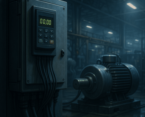
Craig Chamberlin2025-07-22 09:01:002025-07-15 10:33:52Freq Drive Fundamentals: Benefits, Standards & Best‑Fit Products
https://www.precision-elec.com/wp-content/uploads/2025/07/freq-drive-control-panel.png
1024
1024
Craig Chamberlin
https://www.precision-elec.com/wp-content/uploads/2025/02/Precision-Electric-Logo-TEXT-ONLY-Color-NEW.png
Craig Chamberlin2025-07-22 09:01:002025-07-15 10:33:52Freq Drive Fundamentals: Benefits, Standards & Best‑Fit Products https://www.precision-elec.com/wp-content/uploads/2025/07/vfd-variable-frequency-drive.png
1024
1536
Craig Chamberlin
https://www.precision-elec.com/wp-content/uploads/2025/02/Precision-Electric-Logo-TEXT-ONLY-Color-NEW.png
Craig Chamberlin2025-07-21 09:01:002025-07-15 10:20:58VFD Variable Frequency Drive – Ultimate Industrial Guide & Product Picks
https://www.precision-elec.com/wp-content/uploads/2025/07/vfd-variable-frequency-drive.png
1024
1536
Craig Chamberlin
https://www.precision-elec.com/wp-content/uploads/2025/02/Precision-Electric-Logo-TEXT-ONLY-Color-NEW.png
Craig Chamberlin2025-07-21 09:01:002025-07-15 10:20:58VFD Variable Frequency Drive – Ultimate Industrial Guide & Product Picks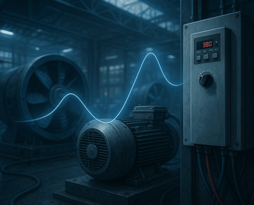 https://www.precision-elec.com/wp-content/uploads/2025/07/vfd-energy-savings.png
1024
1536
Craig Chamberlin
https://www.precision-elec.com/wp-content/uploads/2025/02/Precision-Electric-Logo-TEXT-ONLY-Color-NEW.png
Craig Chamberlin2025-07-20 09:01:002025-07-15 10:09:23VFD Guide: Industrial Efficiency, Specs & Best Products
https://www.precision-elec.com/wp-content/uploads/2025/07/vfd-energy-savings.png
1024
1536
Craig Chamberlin
https://www.precision-elec.com/wp-content/uploads/2025/02/Precision-Electric-Logo-TEXT-ONLY-Color-NEW.png
Craig Chamberlin2025-07-20 09:01:002025-07-15 10:09:23VFD Guide: Industrial Efficiency, Specs & Best Products https://www.precision-elec.com/wp-content/uploads/2025/07/frequency-drive-controls.png
1024
1536
Craig Chamberlin
https://www.precision-elec.com/wp-content/uploads/2025/02/Precision-Electric-Logo-TEXT-ONLY-Color-NEW.png
Craig Chamberlin2025-07-19 09:01:002025-07-15 09:51:40Frequency Drive Applications: Industrial Uses, Benefits & Selection
https://www.precision-elec.com/wp-content/uploads/2025/07/frequency-drive-controls.png
1024
1536
Craig Chamberlin
https://www.precision-elec.com/wp-content/uploads/2025/02/Precision-Electric-Logo-TEXT-ONLY-Color-NEW.png
Craig Chamberlin2025-07-19 09:01:002025-07-15 09:51:40Frequency Drive Applications: Industrial Uses, Benefits & Selection https://www.precision-elec.com/wp-content/uploads/2025/07/variable-frequency-drive-vfd-panel.png
1024
1024
Craig Chamberlin
https://www.precision-elec.com/wp-content/uploads/2025/02/Precision-Electric-Logo-TEXT-ONLY-Color-NEW.png
Craig Chamberlin2025-07-18 09:01:002025-07-15 10:09:58Variable Frequency Drive VFD: Specs, Standards & Case Studies
https://www.precision-elec.com/wp-content/uploads/2025/07/variable-frequency-drive-vfd-panel.png
1024
1024
Craig Chamberlin
https://www.precision-elec.com/wp-content/uploads/2025/02/Precision-Electric-Logo-TEXT-ONLY-Color-NEW.png
Craig Chamberlin2025-07-18 09:01:002025-07-15 10:09:58Variable Frequency Drive VFD: Specs, Standards & Case Studies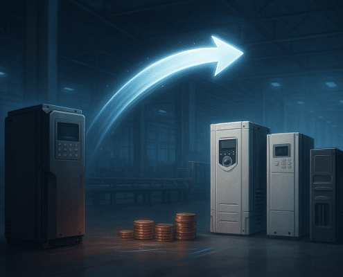 https://www.precision-elec.com/wp-content/uploads/2025/07/powerflex-753-savings.png
1024
1536
Craig Chamberlin
https://www.precision-elec.com/wp-content/uploads/2025/02/Precision-Electric-Logo-TEXT-ONLY-Color-NEW.png
Craig Chamberlin2025-07-17 09:01:002025-07-11 16:13:08PowerFlex 753 Replacement Guide: Cut Costs Without Downtime
https://www.precision-elec.com/wp-content/uploads/2025/07/powerflex-753-savings.png
1024
1536
Craig Chamberlin
https://www.precision-elec.com/wp-content/uploads/2025/02/Precision-Electric-Logo-TEXT-ONLY-Color-NEW.png
Craig Chamberlin2025-07-17 09:01:002025-07-11 16:13:08PowerFlex 753 Replacement Guide: Cut Costs Without Downtime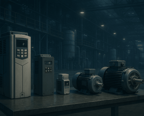 https://www.precision-elec.com/wp-content/uploads/2025/07/ac-electric-motor-speed-control.png
1024
1536
Craig Chamberlin
https://www.precision-elec.com/wp-content/uploads/2025/02/Precision-Electric-Logo-TEXT-ONLY-Color-NEW.png
Craig Chamberlin2025-07-16 09:01:002025-07-11 15:58:05AC Electric Motor Speed Control: Cut Energy Costs with VFDs
https://www.precision-elec.com/wp-content/uploads/2025/07/ac-electric-motor-speed-control.png
1024
1536
Craig Chamberlin
https://www.precision-elec.com/wp-content/uploads/2025/02/Precision-Electric-Logo-TEXT-ONLY-Color-NEW.png
Craig Chamberlin2025-07-16 09:01:002025-07-11 15:58:05AC Electric Motor Speed Control: Cut Energy Costs with VFDs https://www.precision-elec.com/wp-content/uploads/2025/07/ab-vfd-replacement.png
1024
1536
Craig Chamberlin
https://www.precision-elec.com/wp-content/uploads/2025/02/Precision-Electric-Logo-TEXT-ONLY-Color-NEW.png
Craig Chamberlin2025-07-15 09:01:002025-07-11 13:19:01AB VFD Alternatives & Repair
https://www.precision-elec.com/wp-content/uploads/2025/07/ab-vfd-replacement.png
1024
1536
Craig Chamberlin
https://www.precision-elec.com/wp-content/uploads/2025/02/Precision-Electric-Logo-TEXT-ONLY-Color-NEW.png
Craig Chamberlin2025-07-15 09:01:002025-07-11 13:19:01AB VFD Alternatives & Repair https://www.precision-elec.com/wp-content/uploads/2025/07/image-danfoss-vfd-installation.png
1024
1024
Craig Chamberlin
https://www.precision-elec.com/wp-content/uploads/2025/02/Precision-Electric-Logo-TEXT-ONLY-Color-NEW.png
Craig Chamberlin2025-07-14 09:01:002025-07-11 13:07:28Danfoss VFD: Repair, Replacements & Best Practices
https://www.precision-elec.com/wp-content/uploads/2025/07/image-danfoss-vfd-installation.png
1024
1024
Craig Chamberlin
https://www.precision-elec.com/wp-content/uploads/2025/02/Precision-Electric-Logo-TEXT-ONLY-Color-NEW.png
Craig Chamberlin2025-07-14 09:01:002025-07-11 13:07:28Danfoss VFD: Repair, Replacements & Best Practices https://www.precision-elec.com/wp-content/uploads/2025/07/variable-speed-electric-motor-system.png
1024
1024
Craig Chamberlin
https://www.precision-elec.com/wp-content/uploads/2025/02/Precision-Electric-Logo-TEXT-ONLY-Color-NEW.png
Craig Chamberlin2025-07-13 09:01:002025-07-11 12:52:27Variable Speed Electric Motor: Cut Energy Costs with VFD Control
https://www.precision-elec.com/wp-content/uploads/2025/07/variable-speed-electric-motor-system.png
1024
1024
Craig Chamberlin
https://www.precision-elec.com/wp-content/uploads/2025/02/Precision-Electric-Logo-TEXT-ONLY-Color-NEW.png
Craig Chamberlin2025-07-13 09:01:002025-07-11 12:52:27Variable Speed Electric Motor: Cut Energy Costs with VFD Control https://www.precision-elec.com/wp-content/uploads/2025/07/yaskawa-variable-frequency-drive-installation.png
999
1536
Craig Chamberlin
https://www.precision-elec.com/wp-content/uploads/2025/02/Precision-Electric-Logo-TEXT-ONLY-Color-NEW.png
Craig Chamberlin2025-07-12 09:01:002025-07-11 12:40:41Yaskawa Variable Frequency Drive: Buy, Integrate, Save
https://www.precision-elec.com/wp-content/uploads/2025/07/yaskawa-variable-frequency-drive-installation.png
999
1536
Craig Chamberlin
https://www.precision-elec.com/wp-content/uploads/2025/02/Precision-Electric-Logo-TEXT-ONLY-Color-NEW.png
Craig Chamberlin2025-07-12 09:01:002025-07-11 12:40:41Yaskawa Variable Frequency Drive: Buy, Integrate, Save https://www.precision-elec.com/wp-content/uploads/2025/07/siemens-vfd-installation.png
1024
1536
Craig Chamberlin
https://www.precision-elec.com/wp-content/uploads/2025/02/Precision-Electric-Logo-TEXT-ONLY-Color-NEW.png
Craig Chamberlin2025-07-11 12:24:132025-07-11 12:28:36Siemens VFD Selection, Alternatives & Repair Guide
https://www.precision-elec.com/wp-content/uploads/2025/07/siemens-vfd-installation.png
1024
1536
Craig Chamberlin
https://www.precision-elec.com/wp-content/uploads/2025/02/Precision-Electric-Logo-TEXT-ONLY-Color-NEW.png
Craig Chamberlin2025-07-11 12:24:132025-07-11 12:28:36Siemens VFD Selection, Alternatives & Repair Guide


