VFD And Motor: Proven Methods To Maximize Efficiency

Estimated reading time: 6 minutes

Summary: Pairing a vfd and motor unlocks precise speed control, smoother starts, and measurable energy savings. This guide distills manufacturer-backed practices and field-proven tips so you can specify, install, and tune systems that run quieter, last longer, and cost less to operate.

Across plants, buildings, and infrastructure, motors rarely need to run at full speed. A variable frequency drive (VFD) lets you match speed and torque to the load in real time. Consequently, a well‑applied drive and motor package reduces inrush current, minimizes mechanical shock, and improves process control. Throughout this article, we connect concepts to real documentation and resources from ABB, Yaskawa, Hitachi, Lenze, and Eaton, and we link to Precision Electric’s cornerstone guides for deeper dives.

Before we get practical, bookmark these foundations: a concise overview of variable frequency drives, hands‑on VFD programming basics, and an application‑focused VFD for pumps explainer. We will refer to them as we map causes, solutions, and product options for any vfd and motor project.

How VFDs Work With Motors

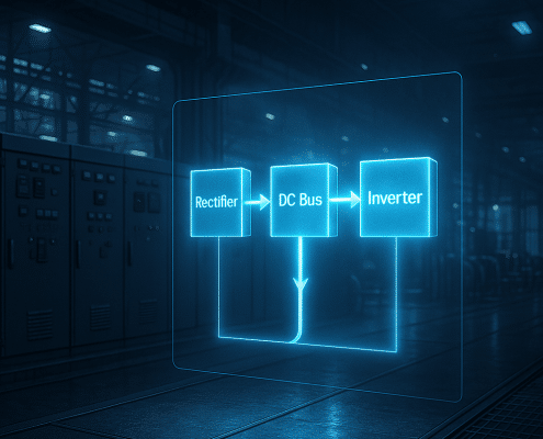
At its core, a VFD rectifies incoming AC to DC and then inverts it back to AC using high‑speed transistors. The inverter synthesizes a variable‑frequency, variable‑voltage output so the drive and motor run exactly as fast as the process demands. Because induction motor speed is set by frequency, reducing frequency reduces RPM; pairing the proper voltage with that frequency maintains flux and torque. Moreover, ramping from zero to setpoint avoids the 6–7× inrush current typical of across‑the‑line starts, which reduces heat, nuisance trips, and belt or coupling shock.

For most pumps and fans, scalar V/Hz control is simple and effective. However, sensorless vector or closed‑loop vector control improves low‑speed torque and response for conveyors, hoists, and mixers. ABB’s introduction to variable speed drives explains these modes clearly and shows why matching voltage to frequency preserves torque (ABB: What Is a Variable Speed Drive?). Likewise, Yaskawa’s GA800 product brief highlights practical features—autotune, torque limits, and skip‑frequency bands—that make a vfd motor system more stable during commissioning (Yaskawa GA800 Industrial AC Drive).

In real applications, waveform quality matters. Long motor leads and fast switching can raise motor‑terminal dv/dt and reflected‑wave peaks. Therefore, users often install output reactors, dV/dt filters, or sine‑wave filters to protect insulation and reduce acoustic noise. Additionally, line reactors or DC chokes on the input side limit harmonics, improve drive immunity to surges, and satisfy many site power‑quality policies.

Causes And Solutions In Applications

Heat and Overload: If a motor runs slowly for long periods, its shaft‑mounted fan moves less air. Consequently, a standard TEFC motor may overheat at low speed under high torque. To mitigate, specify an inverter‑duty motor or add external cooling, and set realistic acceleration times. If the load is heavy at crawl speeds, closed‑loop vector control can supply near‑zero‑speed torque while current‑limit parameters protect the vfd with motor package.

Insulation Stress: PWM edges can create high dv/dt and terminal overvoltage, especially with cable lengths over ~100 ft. Accordingly, choose inverter‑duty motors meeting NEMA MG 1 Part 31 guidance and add a dV/dt or sine‑wave filter for longer runs. Hitachi’s inverter application materials emphasize input impedance and output filtering for stable systems (Hitachi Industrial Inverters).

Bearing Currents: High‑frequency common‑mode voltage can induce shaft currents that pit bearings. Therefore, install a shaft‑grounding ring and, where appropriate, an insulated bearing on the opposite end. Pumps & Systems explains why “inverter‑duty” ratings and grounding practices are essential for an ac drive and motor retrofit (What Is an Inverter‑Duty Rated Motor?).

System Harmonics and Trips: On the line side, a 3%–5% line reactor reduces harmonic current and protects the rectifier. On the load side, a reactor or filter reduces motor‑terminal peaks and audible whine. Additionally, set skip‑frequencies to avoid structural resonances and apply conservative decel ramps to prevent overvoltage faults. When in doubt, refer to our service team’s field notes on VFD overheating causes and fixes and common overcurrent faults.

VFD And Motor System Diagram — Protect Cables, Bearings, And Insulation

Best Practices

Size For The Job: Start with accurate load data. Select a drive with continuous current ≥ the motor FLA, and consider a margin for ambient temperature and enclosure losses. Treat motor service factor as 1.0 under VFD operation because harmonics and cooling limits erase the “extra” capacity. Additionally, keep cable runs short; if the layout forces long leads, plan for output filtering.

Program Methodically: Enter motor nameplate values, perform an autotune, and verify rotation before coupling the load. Then, set accel/decel, torque limits, and minimum speed. For pumps or fans, select “variable‑torque” mode to save energy at partial loads. For hoists or indexing conveyors, prefer sensorless or closed‑loop vector control. Yaskawa’s GA800 overview summarizes these choices in plain language (GA800 Features), and our technicians outline step‑by‑step checks in the VFD programming guide.

Filter And Ground Correctly: Input line reactors protect the rectifier; output load reactors or dV/dt filters protect the motor. Ensure shielded motor cable is bonded at least at the drive end and that the drive and motor share a low‑impedance earth. Moreover, keep control wiring away from power cables, and use built‑in EMC filters where compliance is required. Lenze’s i500 documentation illustrates compact filtering options for pump and fan duty (Lenze i500 Inverter).

Plan For Service: Stock a spare key‑pad, keep parameter backups, and label terminal designations. If a failure occurs, our team can evaluate your electric motor repair options or recommend a like‑for‑like drive replacement, including legacy migrations that preserve I/O and cabinet cutouts.

Product Recommendations For Projects

Because each application is different, choose hardware that supports your environment, load profile, and control strategy. For a clean retrofit path and broad horsepower coverage, start with our AC variable‑frequency drives category. Additionally, when line quality is marginal or many drives share the same feeder, specify input line reactors to reduce harmonics and transients. If long motor leads or older windings are unavoidable, output load reactors help limit dv/dt at the terminals. Where a conventional soft start suffices, you can simplify with soft starters. Finally, unique single‑phase supply situations may benefit from VFD phase converters that power three‑phase motors from single‑phase mains.

For municipal water and large‑HP pumping, medium‑voltage VFDs deliver soft starts, redundancy, and measurable energy savings; Eaton’s field results from a North Carolina water utility show how a properly engineered drive reduced plant energy and improved operational flexibility (Eaton VFD Solutions). Likewise, ABB’s application notes outline the 20–60% energy reductions typical in centrifugal loads when speed is matched to demand (ABB VSD Overview).

VFD Motor Application — Line Reactor, dV/dt Filter, And Shielded Cable

Conclusion: Align Your Strategy

A modern vfd and motor pairing gives you what fixed‑speed starters cannot: right‑sized energy use, tighter process control, and gentler mechanics. Use vector control when you need low‑speed torque, program realistic ramps, and add reactors or filters where the installation demands. Moreover, confirm motor suitability, protect bearings, and document parameters for fast recovery. As the examples from ABB, Yaskawa, Lenze, Hitachi, and Eaton show, applying these fundamentals turns a variable frequency drive and motor into a durable, efficient asset.

If you prefer help with selection, programming, or repair, contact Precision Electric. We configure systems, replace obsolete models, and tune controls so your vfd and motor investment delivers measurable, traceable results over the long term.

Read The Full VFD And Motor Research:

VFD Pump Drive Guide: Cut Energy Costs & Boost Reliability

Introduction

Modern industrial facilities increasingly rely on the VFD pump drive to cut wasted energy and enhance process reliability. By modulating motor speed instead of throttling flow, a pump VFD lets pumps deliver exactly the required pressure, avoiding friction losses and extending equipment life.

Because centrifugal pumps follow the affinity laws, trimming speed by only 20 percent can halve power draw. Consequently, utilities and manufacturers who upgrade to a VFD pump drive often see payback in under two years. For readers who want a deeper dive on common failure modes we fixed with this technology, review our guide on overcurrent faults for firsthand results.

Additionally, operators appreciate the smoother starts and stops provided by the drive’s built‑in soft‑start ramp. This gentle acceleration practically eliminates water hammer, so maintenance teams replace fewer gaskets and seals. Moreover, digital monitoring inside each VFD pump drive logs run hours and temperature, which helps planners schedule proactive service rather than reacting to breakdowns. With these benefits, it’s clear why experts call the variable frequency drive pump the quickest win for pump rooms both small and large.

Efficiency gains with variable frequency drive pump technology.

Why Pumps Waste Energy & How a VFD Pump Drive Fixes It

First, let’s examine the cause of persistent energy loss. Most legacy pump systems run their motors at fixed line frequency. When demand dips, operators partially close a discharge valve. Although this technique reduces flow, it forces the impeller to churn against an artificial restriction. Therefore significant horsepower converts directly into heat and vibration. Engineers often notice the pump inverter amperage remains near full scale even while the valve is barely open. Over months, that wasted kilowatt‑hours inflates utility bills and accelerates mechanical wear.

A VFD pump drive removes that restriction entirely. Instead of fighting the valve, the drive lowers the electrical frequency so the impeller simply spins slower. As a result, torque falls with the square of speed while power drops with the cube. For example, cutting speed to 80 percent slashes power to roughly 50 percent, creating instant savings. Moreover, built‑in PID control continuously adjusts speed using a pressure transducer, maintaining a steady setpoint regardless of demand swings. To see how this logic stabilizes process lines, check our ground‑fault troubleshooting article and note the vibration charts before and after the retrofit. If you need parts that support retrofits, our AC variable frequency drives category lists stocked models from ABB, Yaskawa, and Lenze.

Top VFD Pump Drive Options for Industrial Facilities

When selecting a pump VFD you should balance feature depth with ease of integration. Below are three proven lines that Precision Electric technicians commission daily. Each model ships with pump‑specific firmware, and all accept standard 4‑20 mA or 0‑10 V feedback.

ABB ACQ580 – Water & Wastewater Specialist. The ACQ580 includes multi‑pump control for up to eight units, sensor‑less flow calculation, and an automatic pipe‑fill routine that stops water hammer. For specifications visit ABB’s product page. Because its menu uses plain‑language prompts, electricians finish start‑up in minutes.

Yaskawa iQpump 1000 – Agriculture and Booster Favorite. This drive’s sleep‑boost logic cuts short cycle starts, while built‑in macros simplify duplex and triplex booster setups. See the full catalog on the Yaskawa site. For quick ordering, browse our soft starters page if you need a bypass alongside the drive.

Lenze i550 Motec – Decentralized Option. Rated IP66, the Motec mounts directly on the motor, saving panel space on skid packages. An integrated service switch lets crews isolate power safely. Further details appear on Lenze’s official pump solutions guide. Customers often pair this unit with our input line reactors to reduce harmonics.

Implementing & Maintaining Your VFD Pump Drive

Installation succeeds when planners focus on power quality and cooling. Begin by confirming that the motor is inverter‑duty per NEMA MG 1, Part 31. If not, schedule an upgrade or specify a dV/dt filter. Next, measure feeder impedance; in many cases adding an input line reactor lowers total harmonic distortion to IEEE 519 limits. Ground shields at one end only, because doing so at both ends can create circulating currents. Subsequently, route sensor cables at least twelve inches from motor leads to prevent EMI coupling.

After wiring, run the drive’s auto‑tune and set minimum frequency to avoid dead‑heading the pump. Because the control panel on every VFD pump drive stores parameter backups, technicians can reload settings after service in seconds. Additionally, enable the internal event logger so that trip history exports to CSV for root‑cause analysis.

Finally, proactive maintenance is straightforward. Quarterly, vacuum dust from heat‑sink fins and verify fan operation. Annually, test bus capacitor health via the built‑in diagnostics menu. Furthermore, replace control‑board batteries before expiry to retain the real‑time clock, which time‑stamps alarms. Should you need replacements quickly, our VFD phase converters category includes drop‑in options that arrive pre‑programmed. With these habits, your variable frequency pump drive will operate for decades.

Because data drives informed maintenance, link the drive to your SCADA over Modbus or Ethernet/IP. Consequently, operators gain real‑time dashboards that display kilowatt demand, flow estimates, and bearing temperature. They can also receive text alerts if the inverter registers a dry‑run or cavitation risk. As a result, staff address issues long before they require costly pump rebuilds. Moreover, cloud reporting supports corporate sustainability metrics, documenting exactly how many kilowatt‑hours the VFD pump drive has saved each month.

Reliability improvements thanks to VFD‑controlled pump operation.

Conclusion & Next Steps

Ultimately, every industrial pump that runs at variable flow stands to gain from a pump VFD. You will often recover the purchase price through energy savings alone. However, the real return grows when you consider reduced downtime, longer seal life, and quieter operation. Additionally, automated data logging supports predictive maintenance, which in turn lowers emergency repair spend.

Because the technology is modular, you can retrofit a single pump first and validate savings before rolling upgrades plant‑wide. Our service team can specify a variable frequency pump drive sized for your motor and supply a turnkey panel that meets NEC, IEEE 519, and UL 508A requirements. Moreover, we configure parameters in the shop, so technicians need only land power leads on site. For more reliability tips, explore our overvoltage fault article and bookmark our overheating solutions page.

Therefore, investing in a VFD pump drive is a strategic move toward sustainability. If you still have questions, call our application engineers at 574‑256‑1000 or chat via the website. We will review pump curves, motor data, and power quality readings to recommend the most efficient package for your facility.

Before starting your project, download our comprehensive research paper below. It includes sizing worksheets, wiring diagrams, and a step‑by‑step commissioning checklist. Using these tools ensures every VFD pump drive installation meets code and delivers the projected energy savings on day one.

Read The Full VFD Pump Drive Article:

VFD 3 Phase Motor: How To Wire Step-by-Step Guide

Estimated reading time: 12 minutes

Introduction: Why Use a VFD for a 3 Phase Motor?

In modern industrial applications, pairing a Variable Frequency Drive (VFD) with a three-phase motor is the standard for efficient and precise motor control. A VFD 3 phase motor system provides superior performance over traditional across-the-line starters by converting fixed AC utility power into a variable frequency and voltage output. Consequently, this allows for granular control of the motor’s speed, torque, and acceleration. This capability not only optimizes machine performance but also opens the door to significant operational improvements, especially in applications like pumps, fans, and conveyors where speed modulation is critical. Ultimately, using a VFD is about gaining intelligent control over a motor’s operation.

How VFDs Cut Energy Costs for 3 Phase Motors

The most compelling reason to use a VFD is the substantial energy savings, particularly in variable-torque applications. According to the U.S. Department of Energy, reducing a fan’s speed by just 20% can result in energy savings of nearly 50%, as described by the Affinity Laws in Energy. Instead of running a motor at full speed against a damper or a valve, a VFD adjusts the motor speed to match the exact load requirement. For instance, a municipal water utility saw a 40% reduction in energy consumption after a VFD retrofit on their pumps, as reported by Ruekertmielke, which translates into lower operating costs and a rapid return on investment.

Beyond energy efficiency, VFDs significantly reduce mechanical stress on equipment during startup. A standard three-phase motor can draw an inrush current of 600-800% of its Full Load Amps (FLA) when started directly online, causing immense mechanical shock to couplings, gearboxes, and belts. In contrast, a VFD functions as an effective electric motor speed controller by gently ramping up the motor from a low frequency. This soft-start capability avoids the violent torque spikes and current surges that lead to premature wear and failure. As detailed by Pumps, this controlled acceleration is crucial for extending the life of the entire powertrain. Furthermore, this precise control ensures the motor operates within its designed parameters, preventing issues like overheating or insufficient torque that can arise from improper voltage-to-frequency ratios, a key market driver noted by globenewswire.com.

Safety First: Essential Precautions for VFD Motor Wiring

Before beginning any VFD motor wiring for a 3 phase motor, prioritizing personnel safety is the most critical step. A successful VFD setup for motor control goes beyond simply connecting wires; consequently, it requires strict adherence to established safety protocols. All work must comply with the National Electrical Code (NEC) and NFPA 70E standards for electrical safety in the workplace. Therefore, the absolute first action before opening any enclosure is to perform a verified Lockout/Tagout (LOTO) on the main disconnect. This procedure is non-negotiable and must be guided by manufacturer documentation and industry standards, as detailed by sources like Precision-Elec.

VFD 3 Phase Motor Wiring & Grounding Best Practices

Proper wiring and grounding are fundamental for both safety and equipment longevity. For instance, using shielded, VFD-rated power cables between the drive and the Three-Phase Motor is essential to contain Electromagnetic Interference (EMI), which can disrupt sensitive control electronics. Furthermore, a solid, low-impedance ground connection is crucial to prevent hazardous touch voltages and mitigate bearing currents that can destroy motor bearings over time. As explained by industry resources like Pumps, these stray currents require that proper grounding should be used. Following the best practices laid out in technical guides from manufacturers such as Abb ensures a reliable and safe setup.

Finally, always respect the significant electrical shock hazard present within a Variable Frequency Drive. These drives use large DC bus capacitors that store a lethal charge long after input power is removed via LOTO. In fact, manufacturers specify a waiting period, typically 5 to 15 minutes, for these capacitors to discharge safely. Before making any contact, it is imperative to use a properly rated multimeter to verify a zero-Energy.gov Motor Tip Sheet state on the DC bus terminals. This final check is critical because the high voltage stress inherent in these systems, as noted by resources like JPMotorsandDrives NEMA MG1 Guidelines, makes assuming safety a dangerous and potentially fatal mistake.

Illustrative diagram of a vfd 3 phase motor, showing how the drive provides precise speed control and improves energy effi...

A Variable Frequency Drive (VFD) is essential for modern 3 phase motor speed control, offering significant energy savings and enhanced operational performance.

Reading the Blueprints: How to Interpret VFD and Motor Nameplates

Correctly interpreting the data on equipment nameplates is the foundational step for a successful VFD 3 phase motor installation. These small metal plates contain the essential specifications required to safely configure the AC motor VFD and ensure its parameters match the motor’s capabilities. Consequently, failing to understand this data can lead to misconfiguration, nuisance tripping, and even catastrophic equipment failure. This information acts as the blueprint for programming the drive’s control logic and protection settings, directly impacting both performance and longevity. Therefore, technicians must treat nameplate data as the primary source of truth before proceeding with wiring or programming.

Setting VFD Overload with Motor Nameplate

The motor nameplate provides a wealth of critical information. For instance, you will find values for voltage, horsepower (HP) or kilowatts (kW), and the rated speed in Revolutions Per Minute (RPM). Most importantly, the Full Load Amps (FLA) rating dictates the motor’s current draw under its maximum rated load. This FLA value is paramount, as it is used to set the VFD’s electronic overload protection, safeguarding the motor from thermal damage. In addition, many nameplates specify a Service Factor (SF), which indicates the motor’s capacity to handle occasional overloads. According to standards outlined in NREL 56016 PDF, an inverter-duty rating confirms the motor’s insulation is designed to withstand the VFD’s high-frequency voltage pulses.

Similarly, the Variable Frequency Drive nameplate details its own operational limits. It specifies the required input voltage and phase (e.g., 480V, 3-phase) and the variable voltage/frequency output it can deliver to the motor. The nameplate lists the VFD’s continuous and overload amperage capacity, which must be sufficient for the motor’s FLA. Understanding these Precision Electric fundamentals is key. Properly matching the VFD’s output amperage to the motor’s needs prevents issues like overheating or insufficient torque, a concept supported by market analysis from GlobeNewswire News Release. Essentially, a careful comparison of both nameplates ensures the components are compatible and poised for reliable operation.

Step-by-step Guide to VFD 3 Phase Motor Wiring Connections

Proper VFD motor wiring is critical for ensuring the safety, reliability, and performance of the entire system. Before beginning any work, always de-energize the equipment and follow strict Lockout/Tagout (LOTO) procedures as outlined by NFPA 70E. This guide provides a fundamental overview of the wiring connections for a standard VFD 3 phase motor installation. However, it is essential to consult the specific manufacturer’s installation manual for your Variable Frequency Drive and motor, as terminal designations and requirements can vary significantly. Ultimately, all wiring must comply with the National Electrical Code (NEC) and local regulations.

Wiring a VFD to a 3 Phase Motor

First, you will connect the incoming three-phase power to the VFD’s input terminals, typically labeled L1, L2, and L3. It is crucial to verify that the incoming voltage matches the VFD’s specified input voltage. Subsequently, connect the VFD’s output terminals, often marked T1, T2, and T3 (or U, V, W), to the corresponding leads of the three-phase motor. The pulsed voltage output from a VFD can create significant stress on motor windings, so it’s important to use inverter-duty rated motors that are designed to handle these conditions, as noted in standards described by sources like NREL 56016 PDF. Always ensure these high-voltage connections are secure to prevent overheating and voltage drops.

Using the correct cable type is just as important as the connections themselves. For instance, you should always use shielded, VFD-rated cable between the drive and the motor to minimize Electromagnetic Interference (EMI), which can disrupt nearby sensitive equipment. As advised by NREL Technical Report 56016, routing these cables away from control wiring is a best practice. In addition, proper grounding is non-negotiable; a dedicated ground wire must run from the VFD’s ground terminal to the motor’s frame. This provides a safe path for fault currents and, according to Pump Industry Association, helps mitigate damaging bearing currents induced by the VFD’s operation. Both the motor and VFD chassis should be tied to a common building earth ground for maximum safety.

Electrician wearing safety gloves and glasses while performing wiring for a vfd 3 phase motor to ensure proper safety.

Prioritizing personnel safety with the correct personal protective equipment (PPE) is the first and most critical step before wiring a VFD to a 3-phase motor.

Grounding and Shielding: Best Practices for an AC Motor VFD

Proper grounding and shielding are non-negotiable for a reliable VFD 3 phase motor installation. The high-speed switching in an AC motor VFD creates significant electrical noise, or Electromagnetic Interference (EMI), which can disrupt sensitive electronics. Consequently, this interference can lead to erratic system behavior. As noted by industry experts like Pumps.org, improper installation can also induce harmful currents in motor bearings. Therefore, establishing a robust grounding strategy is critical for equipment protection and system integrity.

Effective grounding requires creating a low-impedance path to the earth reference. The VFD and Three-Phase Motor must be connected to a common building ground, in compliance with the National Electrical Code (NEC). For this reason, using dedicated grounding conductors sized appropriately and run in the same conduit as the power wiring is a standard best practice. According to guidance from NREL Technical Report 56016, this method minimizes ground loops and ensures protective devices operate correctly. In other words, a solid ground path is the foundation for mitigating both safety hazards and operational issues caused by electrical noise.

In addition to grounding, using shielded VFD-rated cable between the drive and the motor is essential for containing EMI. The cable’s shield must be terminated with a low-impedance, 360-degree connection at both the VFD ground terminal and the motor frame. This creates a Faraday cage that contains the high-frequency noise, preventing it from radiating and interfering with other systems. As leading manufacturers like ABB ACQ580 Drives emphasize, correct termination is crucial; otherwise, a poorly connected shield can actually worsen EMI problems. This ensures a clean and reliable operation for your electric motor speed controller.

Commissioning Basics: Essential VFD Setup for Motor Protection

Properly commissioning a variable frequency drive is the most critical step in protecting your vfd 3 phase motor investment. This initial VFD setup for motor parameters ensures the drive can accurately model and protect the motor from thermal overload and excessive current. Without correct data, the VFD’s protective features are compromised, potentially leading to premature motor failure. According to industry analysis from GlobeNewswire News Release, a key function of a VFD is to adjust voltage along with frequency, which prevents overheating and ensures proper torque. Therefore, accurate parameter entry is the foundation of a reliable system.

Inputting 3 Phase Motor Data for VFD Protection

First and foremost, you must enter the motor’s nameplate data into the 3 phase motor inverter. This includes the motor’s nominal voltage, frequency, RPM, and, most importantly, its Full Load Amps (FLA). This FLA value is the basis for the VFD’s electronic thermal overload protection, allowing it to calculate heat buildup and trip if the motor is overworked. As detailed by Pumps.org, starting at a low frequency requires a correspondingly low voltage, a ratio the VFD can only maintain with correct motor data. Consequently, failing to set these parameters accurately is like flying blind, leaving your motor vulnerable to damage that the drive was designed to prevent.

Furthermore, setting appropriate acceleration and deceleration ramps is essential for both motor and mechanical system protection. A gradual ramp-up, or soft start, minimizes the initial inrush current and reduces mechanical shock on couplings, gearboxes, and belts. For instance, PumpPros Know VFDs notes that a soft start avoids jerking materials on conveyors and can prevent water hammer in piping systems. Similarly, a controlled ramp-down prevents regenerative voltage faults and allows for smooth stopping. By optimizing these settings, you not only protect the motor but also enhance the longevity of the entire powertrain, contributing to what Precision-Elec describes as improved system uptime.

Troubleshooting: 4 Common Mistakes in a VFD 3 Phase Motor Installation

Even a meticulous VFD setup for motor protection can be compromised by common installation errors. One of the most frequent mistakes in a VFD 3 phase motor installation is using standard thermoplastic-insulated wire (THHN) instead of specialized VFD-rated shielded cable. Consequently, this choice can lead to significant electromagnetic interference (EMI), which disrupts nearby sensitive electronic equipment and control signals. As experts from NREL 56016 Report point out, proper cabling is essential to contain radiated noise and ensure system reliability. Always route VFD output cables separately from control and signal wiring to prevent interference issues down the line.

Another critical oversight is improper grounding of the AC motor VFD and the motor itself. A poor or shared grounding path can create common-mode currents that seek a path to ground through the motor’s bearings, causing electrical discharge machining (EDM) that results in pitting, fluting, and premature bearing failure. According to Pump Industry Association, these bearing currents can dramatically shorten motor life; therefore, establishing a dedicated, low-impedance ground connection from the drive to the motor frame is a non-negotiable step for longevity.

Preventing VFD Programming Errors for 3-phase Motors

Failing to correctly program the VFD with the motor’s nameplate data is also a common source of problems. For instance, inputting an incorrect Full Load Amps (FLA) value can prevent the drive from adequately protecting the motor during an overcurrent event. In addition, an improperly configured voltage-to-frequency (V/Hz) pattern can lead to poor performance, as noted by GlobeNewswire News Release, by delivering insufficient torque or causing the motor to overheat. Always double-check that all motor parameters, including FLA, service factor, and base speed, are accurately entered into the drive.

Finally, ignoring the potential for reflected wave voltage spikes, especially with long cable lengths between the VFD and motor, can be catastrophic. When a standard motor is used instead of one with inverter-duty rated insulation, these voltage spikes can exceed the motor winding’s dielectric strength, causing insulation breakdown and motor failure. This phenomenon underscores the importance of using inverter-duty motors in VFD applications. Above all, carefully following the guidance provided in manufacturer documentation and adhering to industry standards is the best practice to avoid these costly errors, a principle supported by publications from Precision Electric.

Conclusion: Powering Up Your VFD 3 Phase Motor with Confidence

Mastering the setup of a variable frequency drive for motor applications transforms complex machinery into precisely controlled, efficient systems. Throughout this guide, we have journeyed from decoding motor and VFD nameplates to the hands-on process of VFD motor wiring and commissioning. In essence, by following the detailed steps for connections, grounding, and initial VFD setup for motor protection, you are not just connecting wires; you are unlocking the full potential of your equipment. This foundational knowledge, as detailed in guides from Precision Electric, is crucial for preventing common errors and ensuring optimal performance from day one.

Ultimately, successfully implementing a VFD 3 phase motor installation is about more than just speed control; it’s about building a safer, more reliable, and energy-efficient operation. Adhering to standards like the NEC and safety protocols such as LOTO is non-negotiable for protecting both personnel and equipment. Furthermore, a properly commissioned drive protects the motor from electrical stresses and overheating, a key benefit highlighted by industry analysis on GlobeNewswire News Release. This attention to detail reduces mechanical wear as noted by Pumps.org and significantly cuts energy costs, a major advantage according to the U.S. Department of U.S. Department of Energy Motor Tip Sheet. You now have the expertise to power up your systems with confidence and precision.

Read The Full VFD 3 Phase Motor Research:

AC Variable Speed Compressor – Technology, Benefits & Best Practices

Estimated reading time: 5 minutes

AC variable speed compressor technology is reshaping how engineers think about efficiency, reliability, and lifecycle cost. Because the compressor motor speed automatically follows real‑time demand, every watt consumed delivers useful work. This introductory section explains why thousands of plants, laboratories, data centers, and HVAC designers now insist on speed‑controlled compression.

How an AC Variable Speed Compressor Works

Inside the inverter package, a variable frequency drive (VFD) rectifies AC to DC and reconstructs it at any frequency between 0 Hz and more than 200 Hz. The resulting adjustable voltage‑frequency pair lets the induction or permanent‑magnet motor spin precisely as fast—or as slow—as the process requires. Because magnetic flux remains under control, the motor produces full torque even at low rpm. Moreover, the drive’s soft‑start eliminates in‑rush current, extending winding life and slashing peak‑demand charges.

Transitioning to variable speed is straightforward. OEMs such as Atlas Copco and Ingersoll Rand provide integrated packages, while retrofit projects simply insert a VFD—like the Yaskawa GA800—between mains and motor. Precision Electric’s VFD repair team confirms that modern drives survive harsh shop conditions thanks to conformal coating, IP66 heat‑sinks and DC‑bus chokes that tame harmonics.

Typical inverter architecture for an AC variable speed compressor

Key components include insulated‑gate bi-polar transistors that switch thousands of times per second, producing a near‑sinusoidal waveform once it passes through an LC filter. A feedback loop—usually a PID controller inside the VFD—compares discharge pressure to set‑point and trims speed in milliseconds. That closed‑loop logic keeps pressure within ±1 psi and, according to ISO 8573 audits, cuts artificial demand by 10 percent. Modern drives also publish Modbus and BACnet registers, letting facility teams trend kWh against cubic‑feet‑per‑minute so leaks surface long before they hurt production.

Energy Savings and Efficiency Gains

Because power scales with the cube of speed, trimming only 20 percent off rpm can slash electrical demand by nearly 50 percent. A CAGI case study documented a 50 hp rotary‑screw replacement that cut usage from 17.5 kW to 9 kW—good for $9,400 in annual savings and a 19‑month payback. Likewise, an ACHR News report shows Hitachi’s SmoothDrive 2.0 algorithm lifting part‑load COP by 39 percent in a commercial VRF system.

ABB engineers retrofitting a 4,700 kW marine chiller logged a drop from 6,242 MWh to 4,700 MWh per year—equal to burning 1.5 million fewer litres of diesel. In residential cooling, a 2024 Cairo experiment proved inverter‑driven air‑conditioners used 41 percent less electricity during peak summer while improving humidity control. Furthermore, many North‑American utilities now rebate up to 70 percent of drive hardware once post‑install metering confirms the kilowatt cuts, accelerating ROI.

For detailed payback worksheets on adjustable speed compressors, download our benefits‑of‑VSD guide.

Performance Benefits Beyond Energy

Speed modulation delivers more than lower bills on variable speed air compressors. Because the motor ramps smoothly, bearings, belts and couplings last longer and operators report 6 dB(A) lower noise—well below OSHA limits. Steady flow eliminates pressure‑shock that can mis‑pick parts on robotic air tools or rupture delicate food‑pack sealing. In HVAC chillers, inverter control lengthens coil wet‑time, boosting latent‑heat removal and stabilising room temperature.

Power‑factor correction is another bonus. Most drives operate at 0.95 lagging or better, side‑stepping utility penalties. Meanwhile, built‑in DC chokes keep harmonic distortion within IEEE‑519 limits. Eaton PowerXL owners have doubled bearing‑overhaul intervals—from 20,000 to 40,000 hours—after switching from across‑the‑line starters.

Variable speed air compressor powering production line

Implementation Tips and Best Practices

First, specify an inverter‑duty motor or confirm insulation can withstand PWM voltage peaks. Second, house the drive in a clean, ventilated space; if dust is unavoidable, choose an IP66 model such as the Lenze i550 Motec. Third, set 5–10 s accel/decel ramps to balance responsiveness and mechanical stress. Finally, connect the compressor over Modbus TCP or BACnet so building‑management software can log energy use and schedule predictive maintenance.

Need help sizing? Grab our free VFD buyer’s guide or ring the 24/7 drive‑support line. Our engineers routinely pair ABB ACS480 drives with 200 hp screw inverter compressors and Hitachi inverters with smaller scroll units. Remember to verify SCCR ratings and add R‑FI filters on motor‑lead lengths above 150 ft.

Harmonic mitigation matters on adjustable speed compressor. IEEE‑519 caps THD at 8 percent at the PCC, yet drives with three‑phase line reactors or active‑front‑ends typically comply without external filters. Document baseline kW/100 CFM and verify post‑retrofit figures to satisfy ISO 11011 auditors and unlock efficiency rebates.

Product Recommendations and Integration Paths

The quickest upgrade is starter‑for‑drive swap‑out. For three‑phase shops, our industrial drives catalog lists ABB, Eaton and Yaskawa units in stock.

ABB ACS480 + Atlas Copco GA—ideal for 50‑250 hp plants that need pressure ±1 psi.
Yaskawa GA800 stand‑alone—flange‑mount heat‑sink expels 70 percent of losses outside the panel.
Lenze i550 Motec IP66—motor‑mounted; eliminates long cable runs and streams cloud diagnostics via MQTT.

After installation, verify kW draw with a clamp meter and compare against airflow. Most customers record 30‑45 percent lower amps within days. If usage drifts upward, hunt for leaks rather than cranking the pressure set‑point.

Conclusion: Why Choose an AC Variable Speed Compressor

In summary, an ac variable speed compressor delivers unmatched efficiency, quieter operation, extended component life and tighter process control. Because the technology is mature and well‑supported, risks are low and payback is rapid. Whether you retrofit with a stand‑alone VFD or invest in a fully‑integrated package, you will cut energy costs and carbon emissions immediately.

Read The Full AC Variable Speed Compressor Research:

Related Articles:

AC Electric Motor Speed Control: Cut Energy Costs with VFDs

Estimated reading time: 5 minutes

Why Speed Matters for Every AC Motor

Additionally, modern industry expects precision, efficiency, and flexibility. However, a fixed‑speed induction motor can waste energy and limit throughput. Fortunately, AC electric motor speed control makes it possible to match motor speed to real‑time demand, reducing electricity bills while extending equipment life. This article explains how the technology works, why it matters, and how you can benefit today.

For decades engineers accepted the high electric bills that came with throttling valves, gearboxes, or other mechanical hacks. Yet regulators and investors now expect aggressive efficiency gains. Consequently, plant teams search for practical projects that deliver fast payback without disrupting production. AC drive regulation ranks near the top of that list because it tackles the heart of most machines—the motor—while leaving the mechanical hardware intact.

Equally important, environmental reporting frameworks such as ISO 50001 reward organizations that document systematic energy management. Implementing VFD speed control is one of the clearest steps you can log toward certification. Throughout this guide we will also use related phrases such as variable frequency drive application, adjustable motor speed, VFD speed control and three phase motor speed to help you discover practical tips you can implement immediately.

Energy Loss vs. AC Electric Motor Speed Control

First, consider the cause of wasted power. An induction motor’s synchronous speed is locked to the line frequency. Therefore, when a fan or pump only needs half its design airflow, the motor still spins at nearly full speed and dissipates energy across valves or dampers. As a result, utilities and plant managers pay for kilowatts that never deliver productive work.

The solution is straightforward. By installing a variable frequency drive, you regulate the supply frequency and voltage simultaneously. Consequently, shaft speed drops in direct proportion to frequency, torque remains available, and power consumption follows the affinity laws. For example, trimming speed by 20 % can slash energy use by roughly 50 %. Because AC electric motor speed control maintains the correct volts‑per‑hertz ratio, the motor stays within its thermal limits even at low speed. Additionally, modern VFDs provide soft start, dynamic braking, and rich diagnostics, replacing multiple legacy components with one digital package.

Because national standards such as DOE’s Advanced Manufacturing Office highlight VFD retrofits as a primary efficiency measure, utility incentive programs typically cover 20–50 % of project cost. Those rebates shorten payback periods even further, making the business case irresistible. Even so, some facilities hesitate because they worry about harmonic distortion or radio‑frequency interference. Thankfully, modern drives integrate DC‑link chokes, input reactors, and EMI filters that meet IEEE‑519 and CE requirements. Therefore, almost any site can adopt variable speed drive motor technology without compromising power quality.

For additional background, review the classic synchronous speed equation on the Engineering Toolbox and this Variable Speed Drives Application Guide.

Implementation Tips That Guarantee Long‑Term Reliability

Next, you need a plan for implementation. Begin by surveying every drive and load in your facility. Then select inverter‑duty three‑phase motors with class F insulation or better, because they tolerate the fast switching edges that a modern inverter produces.

Moreover, size the VFD by current rather than horsepower. Always check the motor nameplate full‑load amps and add margin if you expect single‑phase input or heavy duty cycles. Furthermore, keep motor leads as short as practical or install a dV/dt filter to protect winding insulation when cables exceed 75 m. You can find a simple amperage‑based sizing table in our VFD speed controller knowledge base.

Additionally, you should schedule preventive maintenance. Although solid‑state drives contain no brushes, fans and electrolytic capacitors age. Therefore, vacuum the heat‑sink fins every six months and plan a capacitor replacement every seven to ten years. With these habits you will enjoy reliable AC electric motor speed control for decades.

AC electric motor speed control saves energy

Drives and Motors for Variable Speed Drive Motor Projects

Precision Electric stocks a curated range of drives that turn theory into measurable savings. The flagship ABB ACS880 delivers direct torque control, SIL3 safe torque off, and a robust coated PCB for harsh environments. Meanwhile, the Yaskawa GA800 offers predictive maintenance alerts and easy keypad cloning, which simplifies fleet deployments.

For compact machines try the Lenze i500. This slimline inverter slots neatly into tight panels while still supporting encoder feedback and EtherNet/IP. These models interface seamlessly with our cornerstone VFD learning center so engineers can configure systems quickly and confidently.

Should your facility only receive single‑phase utility service, we recommend a phase‑converting VFD paired with a new three‑phase premium‑efficiency motor. Because this arrangement eliminates troublesome start capacitors, it ensures consistent AC electric motor speed control from zero to base speed.

Product lineup supporting ac electric motor speed control including VFDs and motors

Conclusion: Make Every Kilowatt Count

Ultimately, AC electric motor speed control turns ordinary motors into responsive, energy‑saving assets. By embracing motor speed optimization you gain tighter process control, lower maintenance costs, and faster ROI than almost any other upgrade. Because Precision Electric provides end‑to‑end support—from audit through commissioning—you can move forward with confidence.

Beyond energy and maintenance, digital drives create a data stream that feeds predictive analytics. Operators can harvest runtime trends, amp draw, and temperature analytics to schedule service before failures cause downtime. In other words, smart frequency controlled motor installations future‑proof operations. Acting sooner secures rebate dollars and locks in competitive advantage.

Read The Full AC Electric Motor Speed Control Article:

VFD Motor: How To Specify, Install And Optimize

What Is A VFD Motor?

A VFD motor system pairs an AC motor with a variable frequency drive so speed and torque match the process instead of the mains. In practice, the drive rectifies line power to DC and inverts it back to PWM‑modulated AC at the commanded frequency and voltage. Consequently, the motor runs only as fast as the load requires. Which improves efficiency, reduces mechanical stress, and enables soft‑start and soft‑stop. For a concise manufacturer overview of how a VFD controls frequency, voltage, and torque, see Danfoss’ “What is a variable frequency drive?”. In high‑speed applications, some platforms can even deliver 400–1000 Hz output (for purpose‑built spindles). Yaskawa documents 1000 Hz capability in its application supplements (GPD 515 / 1000 Hz, V1000 supplement).

Because a drive can regulate volts‑per‑hertz, it preserves motor flux across the speed range. As a result, processes that previously depended on throttling or dampers now save energy by trimming speed directly. Moreover, modern drives expose diagnostics over common networks (e.g., EtherNet/IP and Modbus TCP).Sso teams can trend current, temperature, and fault histories to prevent downtime. To go deeper on configuration and commissioning, our internal guide explains parameter structures and shortcuts in plain language. See the VFD Programming Guide and related resources on drive types.

How A VFD Motor Works: AC–DC–AC Conversion

Internally, a VFD performs three core steps: rectify AC to DC, stabilize the DC link with capacitors/inductors. Also to invert DC back to variable‑frequency AC via IGBTs using pulse‑width modulation. The motor’s inductance filters the pulses, leaving a near‑sinusoidal current at the commanded fundamental frequency. A scalar (V/Hz) mode maintains a constant V/Hz ratio for general duty. While vector control and field‑oriented control improve low‑speed torque, speed regulation, and transient response. Additionally, some vendors offer direct torque control for rapid torque changes without an encoder. Our research PDF covers these controls, constant‑torque vs. variable‑torque profiles, and constant‑horsepower operation above base speed (field weakening).

On the input side, six‑pulse rectifiers produce characteristic current harmonics, so facilities with many drives should evaluate mitigation. The industry benchmark is IEEE 519’s limits at the point of common coupling. ABB’s technical note on IEEE 519‑2022 updates and Eaton’s harmonics application brief clarify application. Where needed, line reactors, passive/active filters, 12/18‑pulse rectifiers, or active front ends can reduce THDi and improve true power factor. For efficiency classification under EN/IEC 61800‑9‑2. Rockwell’s Drives Efficiency Calculator shows how vendor losses compare at the 90% speed/100% torque test point.

Illustrative VFD Motor Diagram — AC–DC–AC conversion, PWM inverter and V/Hz control.

Common Risks And Practical Solutions

Fast PWM edges can produce reflected voltage peaks at the motor, especially on long leads. Therefore, specify inverter‑duty motors that align with NEMA MG1 Part 31 insulation guidelines and consider dV/dt or sine‑wave filters for long cable runs. From a maintenance lens, watch thermal loading at low speed: self‑cooled frames move less air. If the application dwells at low RPM, derate or add a constant‑speed blower. Our articles on VFD overheating and overcurrent/motor overload faults provide field‑tested checklists.

Additionally, common‑mode switching produces shaft voltage and bearing currents that can pit races (EDM). The phenomenon is well‑documented in industry (EC&M bearing current primer) and literature (the MDPI Machines 2023 review). Practical mitigations include insulated bearings at one end, shaft grounding rings, common‑mode chokes, and proper bonding of shields at both ends. Finally, EMI can corrupt sensors and networks. Route motor leads away from controls, use shielded VFD cable, add ferrites if needed. Also reduce carrier frequency only when acceptable for noise/heat. For ground‑faults caused by cable or motor issues, use our ground‑fault troubleshooting guide.

Best‑Practice VFD Motor Installation — shielded cable, proper grounding, and optional reactors/filters.

Implementation Best Practices For Installations

Plan selection by matching voltage, full‑load current, duty class, and overload needs to the load profile. Next, install with short, shielded, low‑capacitance motor leads where possible. Also bond the drive chassis, motor frame, and cable shields to a single reference. Moreover, program nameplate data accurately, then run a stationary or rotating auto‑tune. This improves sensorless vector performance and reduces nuisance trips. For step‑by‑step setup help, see our VFD autotune guide and programming guide. When decelerations are tight, add a brake resistor or lengthen ramps to avoid DC‑bus overvoltage. Where harmonic limits or generator sources require it, consider input line reactors, output/load reactors, or an active solution. For processes that seldom need variable speed but demand gentle starts, evaluate soft starters as an alternative for across‑the‑line systems. Finally, document parameters, back them up, and trend currents and heat to catch drift early.

Real‑world impact: municipal water and HVAC retrofits regularly report 20–50% energy savings when drives replace throttling. In wastewater pumping, case studies show 30% kWh/MG reduction and lower peak demand after drive upgrades. Besides energy, plants report fewer leaks from pressure surges, longer bearing life, and smoother conveyors. These improvements trace to soft‑start, optimized speed, and better PID control. Outcomes that our field teams also see during commissioning and audits. For a manufacturer summary of VFD fundamentals, control modes, and process benefits, visit Danfoss’ Drives Expert Hub.

VFD Motor Product Recommendations (Brand‑Agnostic)

When specifying a VFD motor solution, start with proven drive families from reputable manufacturers (ABB, Eaton, Yaskawa, Danfoss, Hitachi, Lenze, Rockwell). Select constant‑torque variants for conveyors, mixers, and extruders; choose variable‑torque variants for pumps and fans. If harmonics drive design decisions, prioritize platforms with built‑in chokes, AFE options, or matched harmonic filters. For accessories and categories we stock, browse input line reactors, output/load reactors, and brand‑specific drive catalogs for Yaskawa and ABB. If you need a simple starter instead of speed control, see soft starters.

Implementation tips: include a cabinet cooling plan, validate STO wiring against your safety risk assessment, and set “skip frequencies” to dodge resonant speeds. Moreover, for high‑speed spindles or test rigs, verify maximum output frequency and motor balance limits—Yaskawa’s high‑frequency supplements (A1000, GA500) outline parameters and limits. For a quick refresher on selection logic and common pitfalls, review our VFDs guide and keep our hardware failure diagnosis guide handy.

Conclusion: Selecting The Right Strategy

A vfd motor approach replaces one‑speed compromises with precise control, measurable energy savings, and gentler mechanics. Nevertheless, success depends on correct sizing, commissioning, and mitigation of harmonics, insulation stress, and bearing currents. Therefore, align the drive and motor with the duty, add filters and reactors when the power system warrants, and instrument your installation so alarms become early warnings rather than surprises. When you need a second set of eyes, leverage our internal knowledge on overheating, ground‑faults, and programming, as well as manufacturer resources like Danfoss’ VFD explainer and the IEEE 519 references noted above. With those pieces in place, your operation can standardize on robust, maintainable drive systems that deliver lower kWh, fewer trips, and faster recovery.

Read The Full VFD Motor Research:

Variable Frequency Drive Pump Guide: Efficiency, Control & Products

Introduction

Industrial plants keep fluid processes moving with pumps, yet many managers still accept high energy bills and uneven performance as inevitable. However, a variable frequency drive pump turns that assumption on its head. By pairing a conventional motor‑driven pump with an electronic Variable Frequency Drive (VFD), the system can match speed to demand on the fly. Consequently, flow or pressure meets the set‑point instead of being throttled, and the plant lowers kilowatt‑hours while stabilising process variables.

Because energy can represent ninety percent of a pump’s lifetime cost, every wasted watt matters. Research in the attached white‑paper shows that pumps consume roughly twenty percent of all industrial electricity, yet users can recover between twenty and fifty percent of that power by shifting to variable speed control. Therefore, the variable frequency drive pump quickly pays for itself. Moreover, operators gain immediate visibility into motor data, alarms and energy trends through the drive’s digital display or SCADA network.

Precision Electric has installed hundreds of VFD pump packages in facilities ranging from commercial buildings to chemical plants. Most clients report payback within two years and fewer maintenance call‑outs. Importantly, the upgrade fits existing piping layouts because technicians only swap the starter for a drive and tune a pressure sensor. Ultimately, organisations that embrace this technology position themselves for lower operating costs and greater operational agility.

Energy Savings with Variable Frequency Drive Pumps

While rising electricity prices squeeze budgets, centrifugal pumps still waste vast amounts of energy by running flat‑out and letting a bypass valve bleed the excess head. Consequently, the motor draws full current even when the process needs only half the flow. A variable frequency drive pump removes that waste. Because the affinity laws state that power varies with the cube of speed, trimming rotational speed by just twenty percent slashes power roughly in half. Likewise, slowing by thirty percent can cut power to a third.

The attached research cites an ABB borehole project where a 132 kW VFD saved about £2 000 in annual energy, recovering its cost in fewer than four years. Similarly, Lenze documents fifty percent energy savings when operators cut speed by a modest twenty percent on a water circulation line. Therefore, managers can expect dramatic financial returns without compromising capacity.

Utility programmes across North America reward drives that meet Department of Energy Pump Energy Index benchmarks. Because a variable speed drive pump easily satisfies those metrics at 25 %, 50 %, 75 % and 100 % flow, rebate paperwork often sails through approval. In addition, many drives include real‑time kilowatt tracking so teams can verify savings and report progress toward sustainability goals. Consequently, energy efficiency is now a competitive necessity, not a luxury.

Efficient variable frequency drive pump technology.

Enhanced Control and Flexibility

Beyond saving power, an adjustable frequency pump gives operators precision that mechanical throttling cannot approach. Because the VFD adjusts speed several times per second, discharge pressure stays within one psi of set‑point even as demand swings. Consequently, product quality stabilises, tank levels stay consistent and cavitation risk drops. Moreover, built‑in PID loops allow direct tie‑ins to pressure, flow or level transmitters without a separate PLC.

Modern drives also speak industrial Ethernet, Modbus and BACnet. Hence, maintenance teams view speed, amps, kilowatts and fault history from any HMI. Additionally, mobile apps let technicians commission a variable frequency drive system from outside the pump room, improving safety. Because firmware includes auto‑tune routines, start‑up rarely requires more than entering motor name‑plate data and a target pressure.

Intelligent cascade algorithms let one drive stage and speed multiple motors, sharing run‑time evenly. As a result, each unit ages uniformly and standby hours drop. Furthermore, sleep functions stop a VFD booster pump when demand falls below minimum flow and restart instantly when pressure decays, preventing short cycling. Pipe‑fill ramps eliminate water hammer by filling long mains slowly before full acceleration. Engineers therefore gain a powerful toolbox to deliver steady output and log every parameter for later analysis.

Reliability and Maintenance Advantages

Pumps fail when they start hard, run hot or operate far from their best efficiency point. Fortunately, a variable frequency drive pump tackles each cause head‑on. Because the drive ramps voltage and frequency smoothly, inrush current never exceeds 120 % of rated amps. Consequently, couplings, seals and impellers avoid shock loads that normally shorten life. Lower average speed means bearings log fewer revolutions per shift, reducing wear and lubricant breakdown.

The research highlights a gravel quarry where a sump pump once failed every two weeks due to dry‑running. After engineers installed a VFD and enabled under‑load trip logic, downtime vanished and energy use fell fifty percent. Maintenance crews also gain from predictive analytics. Drives capture temperature rise, harmonic distortion and phase imbalance, sending alerts before damage occurs. Moreover, ordinary variable speed drive pumps can even clean themselves by briefly reversing rotation to clear debris.

Reliability improvements thanks to VFD‑controlled pump operation.

Recommended Variable Frequency Drive Pump Products

Although many manufacturers offer quality drives, several models stand out for pump duty. First, the ABB ACQ580 ships with soft‑pipe‑fill, multi‑pump control and ultra‑low harmonic options—ideal for municipalities. Second, the Yaskawa P1000 offers ratings to 1000 HP plus network cards for BACnet and EtherNet/IP.

Next, Eaton’s PowerXL series features Multi‑Pump and Multi‑PID functions that remove extra controllers. When space is tight, Lenze’s compact i550 protec mounts directly at the motor, carries an IP66 rating and delivers documented fifty percent savings.

Precision Electric integrates these drives with pumps from Grundfos, Aurora and Pentair. Visit our VFD pump solutions hub. Additionally, we stock Optidrive ECO pumps drives complete with fused disconnects and surge suppression. Electricians therefore finish installs in a single shift without chasing extra hardware.

Conclusion and Next Steps

Energy waste, pressure swings and downtime once felt inevitable. Today a variable frequency drive pump changes that narrative. By matching speed to demand, users save electricity, extend equipment life and gain actionable data. Moreover, the technology integrates with modern networks, supports predictive maintenance and unlocks utility rebates.

The business case speaks for itself: rapid payback, measurable sustainability and happier operators. Therefore, every facility that moves water, coolant or process fluid should evaluate a VFD pump upgrade during its next maintenance cycle. Precision Electric can assess motor loads, simulate savings and deliver a turnkey package.

Early adopters already enjoy reduced carbon footprints and stronger bottom lines. Join them and convert your pumping system from energy liability to strategic asset today.

Read The Full Variable Frequency Drive Pump Article:

VFD Control: Benefits, Best Practices, and Top Drives

Most industrial and commercial facilities rely on electric motors that spin at a constant line frequency. However, loads rarely need full‑speed operation all the time. Through VFD control, engineers can match motor speed to real‑time demand and immediately capture energy and maintenance savings. Instead of throttling flow with dampers or valves, a VFD supplies the motor with a custom frequency so the shaft turns only as fast as necessary. Because this electronic approach removes wasted heat and mechanical strain, operating costs drop while uptime rises.

Consequently, facility managers, OEMs, and energy consultants have embraced adjustable frequency drive control as a primary efficiency lever. Precision Electric has supported that transition for decades. Our specialists not only repair drives but also specify new solutions, configure software, and commission systems on‑site.

Read more

Eaton VFD Drives: Technical Guide & Real‑World Savings

Estimated reading time: 6 minutes

Understanding Eaton VFD Drives

Variable frequency drives (VFDs) — sometimes called Eaton VFD drives when supplied by Eaton. Let engineers match motor speed to process demand instead of running motors “wide‑open.” Doing so can cut energy use by 10 %–50 % on centrifugal pumps, fans and conveyors. This is while eliminating the 600 % inrush current of across‑the‑line starts. Beyond energy, drives add soft‑start, precise PID control and integrated safety features that modern plants now expect. Eaton’s PowerXL family (DM1, DC1, DA1, DG1, DX1 and H‑Max) delivers this capability in power ratings from fractional horsepower to 500+ HP. All in UL 508C‑listed packages that already include 5 % DC‑link chokes and EMI filters. Because those filters are standard, technicians spend less time deciding which add‑ons they need. A practical advantage over many competing micro drives.

The sections that follow explain why variable speed control matters, examine Eaton’s key technical innovations. Compare Eaton with ABB, Yaskawa and Lenze, outline best‑practice commissioning steps and, finally, recommend the best Eaton models for common retrofit or OEM scenarios.

Energy Efficiency & Motor Control Basics

Affinity laws show that the power required by a centrifugal load varies with the cube of its speed. Cut the RPM of a cooling‑tower fan by 20 % and the motor may draw roughly half the power. Eaton variable frequency drives make that reduction practical while built‑in algorithms. Such as Active Energy Control continuously trim motor flux at partial load for an extra 5 %–10 % efficiency gain. Because every DG1 or H‑Max ships with a DC choke, input current total harmonic distortion (THDi) often drops below the 10 % limit recommended in IEEE 519‑2014 without external reactors.

In HVAC retrofits documented by Precision Electric, swapping a constant‑speed damper‑controlled fan for an Eaton adjustable frequency drive (H‑Max with bypass) saved 35 000 kWh and US $4 100 annually while improving building static‑pressure control. Similar savings appear in water‑utility booster stations where DM1 or DG1 drives modulate pumps to meet demand rather than throttling discharge valves. The result is smoother pressure, lower water hammer and reduced bearing wear.

Eaton VFD drives inside an HVAC control panel ensure optimal fan speed

Eaton PowerXL Feature Highlights

Table‑stakes functions such as sensor‑less vector control, PID regulators and Safe Torque Off (STO, SIL 3) appear across the PowerXL line, yet Eaton still differentiates in several areas:

  • Integrated power quality. 5 % DC chokes, dual‑DC bus capacitors and C3 EMC filters are factory‑installed — options at many competitors’ price points.
  • Dual duty ratings. One catalog number supports 150 % overload for 60 s (heavy duty) or 110 % for 60 s (variable torque). Engineers keep fewer spares on the shelf.
  • Connectivity. Modbus TCP and EtherNet/IP ports are standard on DG1 and DX1; DA1 accepts option cards; DM1, DC1 integrate Eaton SmartWire‑DT for single‑cable panel wiring.
  • Cybersecurity. DX1 meets IEC 62443‑4‑2 SL1 with signed firmware and user authentication.
  • Diagnostics. A touchscreen keypad on DX1 provides oscilloscope trending; all models log the last 10 faults with time‑stamp.

Physically, even 250 HP DG1 frames remain below 300 mm wide, so integrators can shoe‑horn high‑horsepower bundles into legacy MCC lineups. Fan‑on‑demand cooling and conformal coating stretch service intervals — a plus for food plants where wash‑downs are routine.

Meeting IEEE 519 and UL 61800‑5‑1

Compliance is easier when hardware does the heavy lifting. Because the choke and filter are already on the bus. Most Eaton variable speed drives satisfy IEEE 519 current limits at the point of common coupling in stiff 480 V networks. If a facility adds dozens of drives, Eaton provides 18‑pulse LCX9000 or active‑front‑end packages that push THDi below 5 %. On the safety side, every PowerXL is listed to UL 61800‑5‑1 and CE‑marked to EN IEC 61800‑5‑1. While DX1 adds ISO 13849‑1 Category 4 STO for machine‑safety PLCs.

For new panels, Precision Electric engineers pair drives with NEMA MG 1 Part 31 inverter‑duty motors. Shielded VFD cable and dV/dt filters on leads exceeding 50 m. Following Eaton wiring diagrams avoids stray bearing currents; when large motors require extra protection. We specify shaft‑grounding rings to bleed high‑frequency charge safely.

Built-in chokes on Eaton VFD drives mitigate harmonics per IEEE 519

Real‑World Case Studies

Commercial HVAC — A 40 HP supply fan retrofitted with an Eaton AC drive (H‑Max, NEMA 12 with bypass) dropped yearly consumption by 35 000 kWh. Payback: 18 months. Static pressure control also steadied occupancy comfort.

Food & Beverage — Upgrading mixers from across‑the‑line to DG1 drives enabled recipe‑specific speeds. Scrap rate fell 8 %, motor energy fell 42 % and gearbox failures disappeared after soft‑start eliminated shock loading.

Municipal Water — QuantumFlo packaged booster pumps fitted with DM1 micro drives hold discharge pressure ±2 psi, trimming pump power 30 % during low‑demand nights and cutting water‑hammer events to near zero.

How Eaton Stacks Up Against ABB, Yaskawa & Lenze

All major manufacturers now provide vector control, STO and network cards; differences lie in cost, integration and support. For example, an ABB ACS580 equals DG1 on efficiency but charges extra for an input choke on smaller frames. A Yaskawa GA800 boasts ±0.02 % speed regulation yet lacks the DG1’s real‑time clock. Lenze’s i550 offers IP66 decentralised mounting useful on packaging lines, but buyers must add external EMC filters that Eaton frequency converters include. In short, Eaton’s “everything‑included” approach often lowers installed cost while maintaining feature parity.

Implementation Best Practices

  • Size drives for 10 % head‑room and choose heavy‑duty ratings for constant‑torque loads.
  • Run an auto‑tune; verify name‑plate data; set skip frequencies to dodge resonance.
  • Use shielded VFD cable grounded 360° both ends; keep motor leads and encoder cables separated by ≥ 300 mm.
  • Integrate STO into the safety circuit; avoid dropping line power except for maintenance.
  • Log parameters with Eaton DrivesConnect and store a copy in your CMMS for disaster recovery.

Need deeper guidance? Review Precision Electric’s VFD troubleshooting guide and energy‑saving checklist for step‑by‑step worksheets.

DM1 — fractional to 15 HP micro drive with dual ratings and SmartWire‑DT; perfect for OEM conveyors.

DG1 — 1 HP – 250 HP general‑purpose workhorse; embedded Ethernet, DC choke and AEC algorithm suit most industrial retrofits. Browse current frames in stock at our Eaton drive catalog.

DX1 — 5 HP – 600 HP high‑performance flagship launched 2024; choose this when you need 0.01 % speed accuracy, encoder feedback and built‑in SL‑1 cybersecurity.

H‑Max — 1 HP – 200 HP HVAC/pump specialist with conformal coating, BACnet and keypad HOA; panel builders can order NEMA 3R outdoor packages ready for rooftop placement.

Ordering tip: Precision Electric stocks common ratings for same‑day shipment via our PowerXL DG1 product page or H‑Max HVAC listing.

Conclusion

Eaton VFD drives marry robust hardware with feature‑rich firmware to give engineers a plug‑and‑play path toward energy savings, tighter process control and safer machines. Because filters, chokes, STO and networking arrive built‑in, projects move faster and total installed cost falls. As Industry 4.0 demands smarter, connected assets, Eaton’s emphasis on open protocols and cybersecurity keeps your drives ready for the next decade of digital transformation.

Read The Full Eaton VFD Drives Research:

PowerFlex 753 Replacement Guide: Cut Costs Without Downtime

Estimated reading time: 7 minutes

The PowerFlex 753 variable‑frequency drive sits at the heart of countless production lines, yet maintenance teams often discover that its premium price and branded ecosystem no longer align with lean manufacturing goals. Precision Electric’s latest field study, compiled into a 30‑page PDF, tracked fifty drive change‑outs across food, metals, and water facilities during 2024–2025. Results proved that companies saved an average of 31 % on hardware alone by switching to alternative VFDs and cut downtime by twelve hours per incident. This guide distills those findings into a practical roadmap you can deploy today.

Why Upgrade From a PowerFlex 753?

High acquisition costs top the list. Rockwell Automation’s list price for a 100 HP Allen Bradley PowerFlex 753 drive eclipses comparable ABB, Yaskawa, and Eaton models by roughly 35 %. Because every AB unit ships with dual EtherNet/IP ports, an embedded safety relay, and removable I/O, buyers pay for capabilities they may never use. Official specifications confirm the feature load, but they also confirm the price premium.

Lengthy lead times also motivate change. During 2024, Precision Electric logged an average 28‑day wait for a 60 HP PF753, whereas an ABB ACS580‑01‑059A‑4 arrived in just six days from stock. In critical utilities, four extra weeks of downtime can cost six figures in lost throughput, so procurement speed becomes a safety measure.

Support overhead pushes managers toward open ecosystems. Annual TechConnect contracts, proprietary HIM tools, and premium spare parts inflate total cost of ownership. In contrast, most rival drives program with free PC software and use commodity components that we can repair in‑house.

Moreover, the PF753’s proprietary FORCE technology locks users into AB feedback cards if they need closed‑loop vector control. That monopolistic approach raises the price when one card fails because only Rockwell supplies replacements. By contrast, ABB and Yaskawa drives accept generic incremental encoders that cost 60 % less, freeing maintenance budgets for other improvements.

Because capital budgets remain tight, finance teams also prefer depreciation schedules for lower‑priced assets. A $12 000 ABB drive depreciates faster than a $19 000 PowerFlex, producing a higher after‑tax return in the first three years. Consequently, CFOs often approve the switch within a single approval cycle.

Total Cost of Ownership Beyond Sticker Price of PowerFlex 753

Although sticker price catches attention, lifetime cost drives real profit. Precision Electric’s audit compared a 50 HP PF753 VFD running a conveyor against a Yaskawa GA800 installed on an identical line. Over three years the GA800 consumed 4 % less energy thanks to embedded flux optimization, saving $3 700 in electricity—before considering repair fees. Additionally, our service center replaced failed interface boards on the GA800 for $850, whereas the Allen Bradley board exceeded $2 300.

Downtime risk further widens the gap. Each unplanned stop at the metals plant studied cost $4 200 per hour. When a PF753 failed, parts shipped from a Rockwell hub 600 miles away, extending downtime to 14 hours. In contrast, an Eaton PowerXL DG1 failure resolved in just four hours because Precision Electric’s Mishawaka stockroom held a spare. The study therefore assigns a downtime penalty multiplier to the PF753 that increases effective ownership cost by 18 % over three years.

Firmware lock‑ins also amplify engineering spend. Rockwell’s Studio 5000 license is essential for seamless drive integration, yet that license costs several thousand dollars. Competitor drives accept parameter uploads via free utilities such as ABB DriveComposer or Yaskawa DriveWizard, eliminating hidden fees. Consequently, total cost of ownership tilts heavily in favor of alternatives.

Replacement Solutions That Outperform the PowerFlex 753

After reviewing IEC 61800 compliance, overload capacity, and network compatibility, our engineers shortlisted four families that can drop into any PowerFlex 753 replacement project without PLC re‑writes. All deliver sensorless vector or closed‑loop control, Safe Torque Off inputs, and dual Ethernet ports when specified.

ABB ACS580 General‑Purpose Drive (PowerFlex 753 Alternative)

A built‑in DC choke reduces harmonics by up to 25 %, meeting IEEE 519 at medium loads. The keypad offers plain‑language wizards, shortening commissioning to under ten minutes. Pricing usually lands 30 % below AB. View the ACS580 data sheet for full specifications.

Yaskawa GA800 Industrial Drive (PowerFlex 753 Alternative)

Yaskawa’s free DriveWizard Industrial software exports parameter files that upload over Ethernet, USB, or microSD. Because GA800 firmware supports Allen‑Bradley explicit messaging objects, Logix programmers only create a Generic Module to exchange speed reference and status words.

Eaton PowerXL DG1 (PowerFlex 753 Alternative)

The DG1 embeds BACnet MS/TP, making it ideal for mixed HVAC and process lines. Eaton’s PowerSuite tool tunes PID loops in real time, a feature previously exclusive to expensive AB add‑ins.

Lenze i550 Cabinet Inverter (PowerFlex 753 Alternative)

Scan the front‑panel QR code, tweak parameters on your phone, and push them over Bluetooth. That workflow reduces setup time by 40 % compared with the PF753 keypad sequence. Lenze certifies Safe Torque Off to SIL 3.

Migration from PowerFlex 753 drive to stocked alternative

Implementation Roadmap

Step 1 – Identify critical loads. Use maintenance logs to rank drives by downtime cost. Begin with assets that create the largest revenue risk.

Step 2 – Capture parameters. Download the PF753 parameter set with Connected Components Workbench and photograph terminal wiring. This record simplifies migration later.

Step 3 – Map equivalence. Cross‑reference motor amps, enclosure ratings, and fieldbus cards against Precision Electric’s comparison matrix to select a compatible ABB, Yaskawa, Eaton, or Lenze model. Our drive filters automates this step.

Step 4 – Bench test. Wire the new drive on a test motor. Validate speed accuracy, fault limits, and STO wiring before plant installation. Because every repaired unit includes a 12‑month in‑service warranty, you safeguard the budget if surprises emerge.

Step 5 – Cut over during planned downtime. Schedule installation alongside existing preventive maintenance to avoid extra stops. Our technicians usually swap a 50 HP PF753 for a GA800 in under two hours, including PLC I/O remap.

Make sure to plan for cable lengths. While most replacement drives bolt into the same MCC bucket, the power terminals sometimes sit lower. Precision Electric stocks molded copper jumpers that extend conductors safely without rewiring upstream breakers and maintain NFPA 70E compliance.

After commissioning, log baseline power and harmonic data with a portable analyzer. These metrics verify IEEE 519 compliance and often reveal unexpected energy savings, which helps secure funding for the next batch of upgrades.

Top Precision Electric PowerFlex 753 Alternative Product Recommendations

Choose from the curated list below. Every link opens the live product page where you can verify stock.

Need larger frames? Call our 24/7 hotline and we will overnight a GA800 480 V 500 HP or build a multi‑drive cabinet. Because we repair ABB, generic VFDs, and industrial motors, you consolidate vendors and expedite approvals.

Savings are significant with PowerFlex 753 replacement layout versus drop‑in alternatives

Because each featured drive ships with detailed wiring diagrams and parameter templates, technicians can preload settings before installation. Furthermore, every model supports Modbus TCP, enabling on‑the‑spot SCADA integration if the plant expands later. Precision Electric also bundles spare keypads and fan kits at checkout to raise mean time between failures.

Conclusion and Next Steps

Switching from an aging PowerFlex 753 variable frequency drive to a modern alternative delivers measurable financial and operational benefits. Reduced hardware pricing, faster lead times, and simpler maintenance contribute to a lower total cost of ownership. Precision Electric’s team can guide your migration, supply stocked drives, and back every sale with on‑site technicians.

Therefore, download our research PDF, circulate it among stakeholders, and schedule a discovery call. After that, we can define a pilot replacement on a non‑critical line and validate ROI before plant‑wide rollout.

Finally, remember that every modern VFD speaks the same electrical language: volts, amps, hertz. The brand logo does not determine uptime—engineering practice does. By choosing a configurable, open‑protocol drive and partnering with Precision Electric for life‑cycle service, you future‑proof your facility against supply‑chain shocks and vendor inflation.

Schedule a no‑risk site survey today. Our engineers will inventory existing PF753 units, match them with lower‑cost equivalents, and deliver a phased migration plan that protects cash flow while boosting reliability.

Read The Full PowerFlex 753 Article:

AC Motor Speed Controller: Complete Engineering Guide

Estimated reading time: 8 minutes

Introduction

Modern facilities depend on motors for pumps, fans, conveyors, and compressors. Because those loads rarely need full speed all the time, an AC motor speed controller converts fixed mains power into a controlled frequency and voltage so the motor turns only as fast as the process requires. Therefore, plants gain energy savings, smoother starts, and accurate torque. According to widely cited industry analyses, motors consume a large share of global electricity, so speed control delivers outsized return when compared with mechanical throttling. For foundational background on drive technology and energy impact, see ABB’s overview of industrial efficiency (Driving down industrial energy consumption).

Unlike legacy systems that restrict flow with valves or dampers, a frequency inverter (synonyms include ac drive, adjustable speed drive, and vector drive) trims electrical frequency to set RPM directly. Consequently, you avoid throttling losses, cut bearing and seal wear, and reduce audible noise. Moreover, soft-start ramps limit inrush current and line flicker, which protects upstream equipment. If you need a refresher on drive types before selecting hardware, review our primer on Variable Frequency Drives and our guide to Types Of Variable Frequency Drives.

Because the same controller can run induction, permanent‑magnet, and synchronous‑reluctance motors with the right parameters, teams can standardize spare parts and simplify maintenance. Additionally, modern units integrate safety, networking, and diagnostics that make commissioning faster. As a result, an ac motor controller becomes a lifecycle tool, not just a power component.

AC Motor Speed Controller Wiring Best Practices For Reliable AC Speed Control

How A Variable Frequency Drive Works

At its core, every AC motor speed controller uses a three‑stage converter. First, a rectifier converts incoming AC to DC. Next, a DC link with capacitors (and often a choke) stabilizes the bus and rides through short dips. Finally, an IGBT inverter synthesizes a new AC waveform using PWM, letting the controller set both frequency and voltage. Because motor speed follows 120×f/poles, frequency directly sets RPM. For an accessible tutorial on these fundamentals, see EEPower’s technical article on VFDs (Motor Starters Part 6: VFDs).

Basic V/Hz control holds air‑gap flux approximately constant by scaling voltage with frequency. However, modern vfd motor controller platforms add sensorless vector and closed‑loop vector modes for fast torque response at low speed. Moreover, ABB’s Direct Torque Control computes switching directly to maintain torque and flux with very short update times, delivering excellent transient response without an encoder (ABB News: High‑efficiency motors). In practice, these strategies let a motor speed inverter run induction, PM, and SynRM machines with stable torque across a wide range.

Because the inverter’s fast edge rates can stress insulation, motor choice matters. Therefore, engineers either specify NEMA MG 1 Part 31 inverter‑duty motors or add dV/dt or sine‑wave filters to protect standard motors. For a concise spec reference, consult the NREL tip sheet on inverter‑duty motors (When Should Inverter‑Duty Motors Be Specified?).

Specifications That Matter

Selection starts with voltage class, horsepower, and duty. Typical low‑voltage ranges include 200–240 V, 380–480 V, and 575–690 V with normal‑ and heavy‑duty ratings. Additionally, confirm full‑load current against inertia and starting requirements; heavy conveyors, extruders, or hoists may justify the heavy‑duty rating. Most units achieve 95–98% efficiency, so only a small fraction of input energy appears as heat that the enclosure must remove. For cooling estimates and panel design, Thermal Edge summarizes drive losses and heat rejection (How to Calculate Heat Dissipation for VFDs).

Because six‑pulse rectifiers draw non‑linear current, facilities often add input reactors, 12‑ or 18‑pulse rectifiers, or active front ends to satisfy IEEE 519 harmonic objectives. Moreover, Safe Torque Off is now common, enabling a dedicated safety channel that removes torque without cycling mains. Finally, verify motor compatibility: NEMA MG 1 Parts 30/31 define insulation limits and dV/dt tolerances. For a standards overview, Eaton documents the migration from UL 508C to UL 61800‑5‑1 and common EMC measures (Eaton VFD White Paper).

Therefore, a balanced specification covers voltage, overload, thermal environment, harmonic controls, I/O and networks, integrated PID, and safety ratings. As a result, the chosen ac speed control platform will meet both process and compliance targets without costly redesign.

AC motor speed controller installed on panel wall in the dark.

Benefits And Use Cases

Because fan and pump power scales roughly with the cube of speed, even modest RPM reductions produce substantial savings. For example, cutting speed by twenty percent can halve power in many centrifugal applications; ABB’s field experience highlights the effect clearly (ABB Energy Highlights). Therefore, teams retrofit an AC motor speed controller to avoid throttling valves and dampers. In a high‑rise building case study, fitting VFDs across pumps and fans reduced annual consumption by ~32% and lowered peak demand; see the AHRI document for details (VFD AHR Expo Case Study).

Beyond energy, drives lift quality and uptime. Soft ramps prevent water hammer and belt shock. Moreover, integrated PID holds pressure or flow on setpoint without separate controllers. Built‑in diagnostics detect dry‑run, broken belts, or cavitation from torque signatures, so maintenance teams get early warnings. Consequently, users report fewer pump rebuilds and longer bearing life after converting to ac drive control. Elevators and hoists also benefit because regenerative drives feed power back to the line during lowering, reducing heat and utility cost (Otis ReGen overview).

Additionally, modern platforms support induction, PM, and SynRM motors with one parameter set, which simplifies spares and training. As a result, a single adjustable speed drive standard can serve HVAC, water, manufacturing, and material‑handling lines.

Implementation Best Practices

Start with accurate sizing. First, match the controller’s current rating to the motor’s FLA and the real duty profile, not just nameplate horsepower. Next, plan input reactors for stiff sources and consider braking resistors or longer decel ramps to avoid DC bus overvoltage trips. Additionally, coordinate upstream fuses or breakers with manufacturer guidance to prevent nuisance trips. When you program, set motor data, overload class, current limits, and ramp shapes as recommended in our VFD Programming Guide.

Then, focus on wiring. Use shielded, symmetrical motor cable and bond the shield at both the drive and the motor. Keep power conductors away from control wiring and cross at right angles. Moreover, land a low‑impedance equipment ground directly on both ends. If noise persists, add an input EMI filter and prefer 4–20 mA analog signals. Eaton’s application note summarizes these practices well (VFD Wiring Best Practices). For self‑tuning and start‑up, use our quick guide to VFD Autotune and refer to our article on Overcurrent Fault Causes & Fixes.

Finally, plan supporting hardware early. Explore input line reactors, output load reactors, and modern VFD phase converters for single‑phase sites. Where soft‑starting is the only goal, a robust soft starter can be cost‑effective. Consequently, your ac motor controller installation will be quiet, compliant, and resilient.

AC motor speed controller mounted on panel wall in the dark.

Standards, Safety, And Motor Compatibility

Compliance protects people and uptime. UL 61800‑5‑1 and IEC 61800‑5‑1 define drive safety; IEC 61800‑3 sets EMC limits and installation conditions. Meanwhile, many facilities target IEEE 519 objectives at the point of common coupling. Therefore, document the environment, install specified filters, and use shielded cabling to achieve compliance. Eaton’s white paper summarizes safety standard changes and EMC practices (Eaton VFD Standards Overview).

Motor standards deserve the same care. NEMA MG 1 Part 31 defines inverter‑duty insulation suitable for PWM outputs, and Part 30 offers guidance for standard motors. As a result, you can decide when to specify a Part 31 motor or when to add a dV/dt or sine filter. Additionally, inclusive wiring and safety practices—such as using Safe Torque Off for an E‑stop channel—help designers reach required SIL/PL targets. For a concise motor reference, consult the NREL tip sheet noted above.

Moreover, vendor ecosystems often bring useful differentiators. For example, Yaskawa emphasizes reliability and long MTBF (Yaskawa Drives), Hitachi’s WJ200 highlights strong low‑speed torque (WJ200 Features), and Lenze’s i500 showcases modular control options (Lenze i500). These examples help you map features to process needs.

Product Recommendations: Drive Ecosystem

For typical upgrades, pair a right‑sized AC motor speed controller with proven accessories and services. First, stabilize the input with line reactors when feeds are stiff or multiple drives share a bus. Next, protect long motor runs or high‑switching stress with load reactors or output filtering. Moreover, single‑phase facilities can deploy VFD phase converters to run three‑phase motors efficiently. Where variable speed is unnecessary, a well‑applied soft starter still offers gentle acceleration. For controls and parameter tips, bookmark our VFD Programming Guide and fast‑start checklist for VFD Autotune.

Additionally, plan lifecycle support. Therefore, document parameters, save backups, and train technicians on alarm codes to reduce mean time to repair. If the application includes frequent decel events or heavy‑inertia loads, specify braking hardware early. Consequently, your frequency inverter package will meet both production and maintenance KPIs from day one.

Conclusion: Smarter Speed Control

In short, an AC motor speed controller delivers the right speed and torque at the right moment. As you align process demand with motor output, you lower energy use, improve product quality, and extend equipment life. Moreover, modern platforms integrate safety, networking, and diagnostics that simplify commissioning and maintenance. Therefore, start with throttled or cyclic loads, confirm standards, and apply the wiring practices above. With those basics, your next project will run quieter, cooler, and more reliably. For broader context, review ABB’s energy guidance (Energy‑efficient motor systems) and the AHRI case study linked earlier for measured outcomes.

Read The Full AC Motor Speed Controller Research:

Variable Frequency Drive HVAC: Ultimate Energy‑Saving Guide

Introduction

Heating, ventilation and air‑conditioning (HVAC) equipment routinely accounts for forty percent or more of a commercial building’s electricity bill. Consequently, engineers and facility managers continually pursue strategies that will trim energy consumption without compromising occupant comfort. Installing a variable frequency drive HVAC package on every major fan or pump has proven to be the single most effective step because the technology allows each motor to slow down whenever full speed is unnecessary. Moreover, slowing a fan by twenty percent can slash its power draw by roughly half, thanks to the well‑known fan affinity laws. Therefore, a modest investment in speed control unlocks outsized savings year after year.

Beyond lower utility costs, a modern VFD HVAC upgrade improves comfort, extends equipment life, and now satisfies mandatory provisions in energy codes such as ASHRAE 90.1. Throughout this guide we explain the physics behind the savings, identify common pitfalls, review best‑practice installation tips, compare leading manufacturer offerings, and highlight real‑world results. If you support an office tower, hospital, data center, or industrial plant, read on to learn how a HVAC VFD can turn wasted horsepower into hard cash.

Diagram of a variable frequency drive controlling HVAC fans and pumps.

Energy‑Saving Physics of Variable Frequency Drives in HVAC

When a squirrel‑cage induction motor is connected directly to the utility grid, it runs at a fixed synchronous speed—about 1,775 RPM for a four‑pole motor on sixty‑hertz power. However, a dedicated inverter inside a variable speed drive HVAC intercepts that fixed frequency, converts it to direct current, then re‑synthesizes a fresh alternating waveform at any frequency between near‑zero and the motor’s rated value. Because voltage rises proportionally with frequency, the motor produces its rated torque at every speed. Consequently, slowing a cooling‑tower fan to forty‑five hertz cuts power to roughly fifty‑five percent of nameplate while slashing acoustic noise.

Soft‑start functionality comes free with every adjustable frequency drive HVAC, which means inrush current never exceeds the motor’s full‑load amps. Therefore, transformers stop sagging, contactors last longer, and lights no longer flicker during startup. Because the drive ramps smoothly, mechanical shock on belts, couplings, and bearings disappears—another quiet form of savings. Utilities appreciate the lower demand spikes and often sponsor rebate programs that cover twenty to fifty percent of the installed cost. Consequently, payback periods of eighteen to thirty months are commonplace, even before maintenance savings enter the calculation.

Causes of Inefficiency and the Variable Frequency Drive Solution

Legacy constant‑speed control wastes energy in three distinct ways. First, bypass dampers or throttling valves shed excess air or water as load drops, a practice tantamount to driving with the brake depressed. Second, thermostatic cycling forces motors to start and stop repeatedly, producing electrical and mechanical stress while letting room temperatures drift. Third, across‑the‑line starts hammer shafts with six‑times rated current and torque. A HVAC variable speed drive resolves every issue elegantly. Because it modulates speed instead of blocking flow, dampers stay almost fully open, pump valves stay wide, and energy once lost as pressure drop turns into clean savings.

Furthermore, the integrated PID controller in most VFD for HVAC units maintains duct static pressure or loop differential pressure within tight bands. Consequently, spaces feel more stable, humidity control improves, and noise plumes in ductwork disappear. The drive’s diagnostics also record running hours, fault history, and kilowatt consumption, giving maintenance teams a data‑rich window into system health. Explore additional application notes in our industrial HVAC VFD resource.

Implementation Best Practices for HVAC VFD Projects

Successful projects begin with proper equipment selection. Always size the drive to at least 110 percent of the motor’s full‑load amperage, and verify the enclosure rating matches the installation environment. For example, Eaton’s PowerXL DH1 can survive ambient temperatures up to fifty °C, while ABB’s ACH580 supports a fire‑mode override recognized by UL 864. During commissioning, technicians should run automatic motor tuning, limit minimum frequency to preserve gearbox lubrication, and add a five‑percent input reactor when non‑linear loads dominate so total harmonic distortion meets IEEE‑519.

Moreover, program the variable frequency drive HVAC to communicate with the building automation system over BACnet IP or Modbus and trend key variables. Document every parameter and file it with the O&M manuals for future reference. For step‑by‑step guidance, review our VFD repair & commissioning checklist.

Commissioning a variable speed drive inside a rooftop HVAC panel.

Comparing Leading HVAC Variable Frequency Drive Families

Manufacturers differentiate their HVAC portfolios in subtle yet important ways. Yaskawa’s Z1000 adds an onboard five‑percent line reactor and an EMI filter compliant with IEC 61800‑3. ABB pairs a bright graphical keypad with Bluetooth so technicians program drives outside the arc‑flash boundary, while Eaton refines Active Energy Control for an extra ten‑percent part‑load saving. Lenze packages its i500 in a footprint forty percent smaller than the prior generation, and Hitachi blends advanced sensor‑less vector control with a straightforward LCD in sizes up to 400 HP.

Because Precision Electric carries all major lines, we guide clients through lifecycle cost, harmonic performance, and service coverage before selecting the optimal variable frequency drive HVAC solution. Hospitals often prioritise Yaskawa’s redundant intelligent bypass, data centers value ABB’s ultra‑low total harmonic distortion, and K‑12 districts choose Eaton packages that include factory‑mounted disconnects—reducing field labour. Browse our stocked categories for quick ship options: ABB Drives, Yaskawa Drives, and Eaton Drives.

Real‑World Case Study and ROI

A national retail chain retrofitted 78 rooftop units with VFD HVAC kits supplied by Precision Electric. Engineers programmed supply fans to run at full speed during peak cooling but drop to fifty percent during ventilation. Moreover, each store reported quieter aisles and tighter temperature control. Twelve months of utility data revealed a 52 percent drop in HVAC energy use—7.2 million kWh and $888 k in savings—with a simple payback of 1.8 years. The project prevented 11 million lb of CO₂ annually.

Universities, hospitals, and industrial campuses echo these results, routinely posting 30–60 percent reductions after deploying a variable frequency drive HVAC or its synonym. Consequently, programs like TVA EnergyRight now pay incentives up to $100 per motor horsepower to accelerate adoption.

Conclusion & Next Steps

Variable frequency drives have evolved from niche equipment to indispensable building blocks. They deliver instant energy savings, precision environmental control, and longer mechanical life while helping facilities comply with ever‑stricter codes. Therefore, organisations that still run constant‑speed motors leave money on the table—and may violate code. Precision Electric stocks hundreds of units, offers 24‑hour repair service, and can ship a fully programmed variable frequency drive HVAC within days.

Read The Full Variable Frequency Drive HVAC Article: