 https://www.precision-elec.com/wp-content/uploads/2025/09/ac-motor-with-vfd-speed-controller.png
1024
1024
Craig Chamberlin
https://www.precision-elec.com/wp-content/uploads/2025/02/Precision-Electric-Logo-TEXT-ONLY-Color-NEW.png
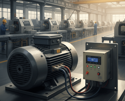
Craig Chamberlin2025-09-27 09:01:102025-09-19 14:34:20AC Motor with VFD: How To Wire, A Step-by-Step Guide
https://www.precision-elec.com/wp-content/uploads/2025/09/ac-motor-with-vfd-speed-controller.png
1024
1024
Craig Chamberlin
https://www.precision-elec.com/wp-content/uploads/2025/02/Precision-Electric-Logo-TEXT-ONLY-Color-NEW.png
Craig Chamberlin2025-09-27 09:01:102025-09-19 14:34:20AC Motor with VFD: How To Wire, A Step-by-Step Guide https://www.precision-elec.com/wp-content/uploads/2025/09/selecting-a-vfd-for-3-phase-motor.png
1024
1024
Craig Chamberlin
https://www.precision-elec.com/wp-content/uploads/2025/02/Precision-Electric-Logo-TEXT-ONLY-Color-NEW.png
Craig Chamberlin2025-09-27 09:01:102025-09-19 14:25:14VFD for 3 Phase Motor: How to Choose the Right One
https://www.precision-elec.com/wp-content/uploads/2025/09/selecting-a-vfd-for-3-phase-motor.png
1024
1024
Craig Chamberlin
https://www.precision-elec.com/wp-content/uploads/2025/02/Precision-Electric-Logo-TEXT-ONLY-Color-NEW.png
Craig Chamberlin2025-09-27 09:01:102025-09-19 14:25:14VFD for 3 Phase Motor: How to Choose the Right One https://www.precision-elec.com/wp-content/uploads/2025/09/allen-bradley-vfd-troubleshooting-guide.png
1024
1024
Craig Chamberlin
https://www.precision-elec.com/wp-content/uploads/2025/02/Precision-Electric-Logo-TEXT-ONLY-Color-NEW.png
Craig Chamberlin2025-09-27 09:01:102025-09-19 14:26:44Allen Bradley VFD: The Ultimate Troubleshooting Guide
https://www.precision-elec.com/wp-content/uploads/2025/09/allen-bradley-vfd-troubleshooting-guide.png
1024
1024
Craig Chamberlin
https://www.precision-elec.com/wp-content/uploads/2025/02/Precision-Electric-Logo-TEXT-ONLY-Color-NEW.png
Craig Chamberlin2025-09-27 09:01:102025-09-19 14:26:44Allen Bradley VFD: The Ultimate Troubleshooting Guide https://www.precision-elec.com/wp-content/uploads/2025/09/allen-bradley-variable-frequency-drive-selection-guide.png
1024
1024
Craig Chamberlin
https://www.precision-elec.com/wp-content/uploads/2025/02/Precision-Electric-Logo-TEXT-ONLY-Color-NEW.png
Craig Chamberlin2025-09-27 09:01:102025-09-19 14:19:38Allen Bradley Variable Frequency Drive: A Selection Guide
https://www.precision-elec.com/wp-content/uploads/2025/09/allen-bradley-variable-frequency-drive-selection-guide.png
1024
1024
Craig Chamberlin
https://www.precision-elec.com/wp-content/uploads/2025/02/Precision-Electric-Logo-TEXT-ONLY-Color-NEW.png
Craig Chamberlin2025-09-27 09:01:102025-09-19 14:19:38Allen Bradley Variable Frequency Drive: A Selection Guide https://www.precision-elec.com/wp-content/uploads/2025/09/technician-installing-allen-bradley-vfd-drives.png
1024
1024
Craig Chamberlin
https://www.precision-elec.com/wp-content/uploads/2025/02/Precision-Electric-Logo-TEXT-ONLY-Color-NEW.png
Craig Chamberlin2025-09-26 09:01:102025-09-19 14:16:33Allen Bradley VFD Drives: A Beginner’s Programming Guide
https://www.precision-elec.com/wp-content/uploads/2025/09/technician-installing-allen-bradley-vfd-drives.png
1024
1024
Craig Chamberlin
https://www.precision-elec.com/wp-content/uploads/2025/02/Precision-Electric-Logo-TEXT-ONLY-Color-NEW.png
Craig Chamberlin2025-09-26 09:01:102025-09-19 14:16:33Allen Bradley VFD Drives: A Beginner’s Programming Guide https://www.precision-elec.com/wp-content/uploads/2025/09/ac-motor-vfd-variable-frequency-drive.png
1024
1024
Craig Chamberlin
https://www.precision-elec.com/wp-content/uploads/2025/02/Precision-Electric-Logo-TEXT-ONLY-Color-NEW.png
Craig Chamberlin2025-09-25 09:01:102026-03-03 16:42:15AC Motor VFD: A Guide to How It Works and Key Benefits
https://www.precision-elec.com/wp-content/uploads/2025/09/ac-motor-vfd-variable-frequency-drive.png
1024
1024
Craig Chamberlin
https://www.precision-elec.com/wp-content/uploads/2025/02/Precision-Electric-Logo-TEXT-ONLY-Color-NEW.png
Craig Chamberlin2025-09-25 09:01:102026-03-03 16:42:15AC Motor VFD: A Guide to How It Works and Key Benefits https://www.precision-elec.com/wp-content/uploads/2025/09/3-phase-motor-with-vfd-wiring-setup.png
1024
1024
Craig Chamberlin
https://www.precision-elec.com/wp-content/uploads/2025/02/Precision-Electric-Logo-TEXT-ONLY-Color-NEW.png
Craig Chamberlin2025-09-24 09:01:102025-09-26 07:24:403 Phase Motor with VFD: A Beginner’s Wiring Guide
https://www.precision-elec.com/wp-content/uploads/2025/09/3-phase-motor-with-vfd-wiring-setup.png
1024
1024
Craig Chamberlin
https://www.precision-elec.com/wp-content/uploads/2025/02/Precision-Electric-Logo-TEXT-ONLY-Color-NEW.png
Craig Chamberlin2025-09-24 09:01:102025-09-26 07:24:403 Phase Motor with VFD: A Beginner’s Wiring Guide https://www.precision-elec.com/wp-content/uploads/2025/09/vfd-3-phase-motor-wiring-safety-precautions.png
1024
1024
Craig Chamberlin
https://www.precision-elec.com/wp-content/uploads/2025/02/Precision-Electric-Logo-TEXT-ONLY-Color-NEW.png
Craig Chamberlin2025-09-23 09:01:102025-09-19 09:20:02VFD 3 Phase Motor: How To Wire Step-by-Step Guide
https://www.precision-elec.com/wp-content/uploads/2025/09/vfd-3-phase-motor-wiring-safety-precautions.png
1024
1024
Craig Chamberlin
https://www.precision-elec.com/wp-content/uploads/2025/02/Precision-Electric-Logo-TEXT-ONLY-Color-NEW.png
Craig Chamberlin2025-09-23 09:01:102025-09-19 09:20:02VFD 3 Phase Motor: How To Wire Step-by-Step Guide https://www.precision-elec.com/wp-content/uploads/2025/09/what-is-a-3-phase-motor-vfd.png
1024
1024
Craig Chamberlin
https://www.precision-elec.com/wp-content/uploads/2025/02/Precision-Electric-Logo-TEXT-ONLY-Color-NEW.png
Craig Chamberlin2025-09-23 09:01:102025-09-19 10:15:553 Phase Motor VFD: A Guide to Choosing the Right One
https://www.precision-elec.com/wp-content/uploads/2025/09/what-is-a-3-phase-motor-vfd.png
1024
1024
Craig Chamberlin
https://www.precision-elec.com/wp-content/uploads/2025/02/Precision-Electric-Logo-TEXT-ONLY-Color-NEW.png
Craig Chamberlin2025-09-23 09:01:102025-09-19 10:15:553 Phase Motor VFD: A Guide to Choosing the Right One https://www.precision-elec.com/wp-content/uploads/2025/09/3-phase-motor-and-vfd-setup.png
1024
1024
Craig Chamberlin
https://www.precision-elec.com/wp-content/uploads/2025/02/Precision-Electric-Logo-TEXT-ONLY-Color-NEW.png
Craig Chamberlin2025-09-22 09:01:102025-09-19 09:15:513 Phase Motor and VFD: Step-by-Step Wiring Guide
https://www.precision-elec.com/wp-content/uploads/2025/09/3-phase-motor-and-vfd-setup.png
1024
1024
Craig Chamberlin
https://www.precision-elec.com/wp-content/uploads/2025/02/Precision-Electric-Logo-TEXT-ONLY-Color-NEW.png
Craig Chamberlin2025-09-22 09:01:102025-09-19 09:15:513 Phase Motor and VFD: Step-by-Step Wiring Guide https://www.precision-elec.com/wp-content/uploads/2025/09/selecting-the-right-siemens-vfd-drives.png
1024
1024
Craig Chamberlin
https://www.precision-elec.com/wp-content/uploads/2025/02/Precision-Electric-Logo-TEXT-ONLY-Color-NEW.png
Craig Chamberlin2025-09-21 09:01:302025-09-19 09:16:29Siemens VFD Drives: A Beginner’s Selection Guide
https://www.precision-elec.com/wp-content/uploads/2025/09/selecting-the-right-siemens-vfd-drives.png
1024
1024
Craig Chamberlin
https://www.precision-elec.com/wp-content/uploads/2025/02/Precision-Electric-Logo-TEXT-ONLY-Color-NEW.png
Craig Chamberlin2025-09-21 09:01:302025-09-19 09:16:29Siemens VFD Drives: A Beginner’s Selection Guide https://www.precision-elec.com/wp-content/uploads/2025/09/powerflex-755-safety-procedures-lockout-tagout.png
1024
1024
Craig Chamberlin
https://www.precision-elec.com/wp-content/uploads/2025/02/Precision-Electric-Logo-TEXT-ONLY-Color-NEW.png
Craig Chamberlin2025-09-20 09:01:542025-09-19 09:17:04Powerflex 755: Troubleshooting Common Fault Codes Guide
https://www.precision-elec.com/wp-content/uploads/2025/09/powerflex-755-safety-procedures-lockout-tagout.png
1024
1024
Craig Chamberlin
https://www.precision-elec.com/wp-content/uploads/2025/02/Precision-Electric-Logo-TEXT-ONLY-Color-NEW.png
Craig Chamberlin2025-09-20 09:01:542025-09-19 09:17:04Powerflex 755: Troubleshooting Common Fault Codes Guide


