 https://www.precision-elec.com/wp-content/uploads/2025/02/Precision-Electric-Logo-TEXT-ONLY-Color-NEW.png
0
0
Craig Chamberlin
https://www.precision-elec.com/wp-content/uploads/2025/02/Precision-Electric-Logo-TEXT-ONLY-Color-NEW.png
Craig Chamberlin2015-10-02 12:24:082015-10-02 12:24:10ABB ACS355 Emergency Stop
https://www.precision-elec.com/wp-content/uploads/2025/02/Precision-Electric-Logo-TEXT-ONLY-Color-NEW.png
0
0
Craig Chamberlin
https://www.precision-elec.com/wp-content/uploads/2025/02/Precision-Electric-Logo-TEXT-ONLY-Color-NEW.png
Craig Chamberlin2015-10-02 12:24:082015-10-02 12:24:10ABB ACS355 Emergency Stop https://www.precision-elec.com/wp-content/uploads/2014/09/preventive-maintenance-vfd.jpg
1060
1500
Craig Chamberlin
https://www.precision-elec.com/wp-content/uploads/2025/02/Precision-Electric-Logo-TEXT-ONLY-Color-NEW.png
Craig Chamberlin2014-09-17 14:28:492015-07-31 11:41:49Preventive Maintenance VFD
https://www.precision-elec.com/wp-content/uploads/2025/02/Precision-Electric-Logo-TEXT-ONLY-Color-NEW.png
0
0
Craig Chamberlin
https://www.precision-elec.com/wp-content/uploads/2025/02/Precision-Electric-Logo-TEXT-ONLY-Color-NEW.png
Craig Chamberlin2014-04-29 14:03:142015-11-17 10:10:23What Is A Variable Frequency Drive
https://www.precision-elec.com/wp-content/uploads/2014/09/preventive-maintenance-vfd.jpg
1060
1500
Craig Chamberlin
https://www.precision-elec.com/wp-content/uploads/2025/02/Precision-Electric-Logo-TEXT-ONLY-Color-NEW.png
Craig Chamberlin2014-09-17 14:28:492015-07-31 11:41:49Preventive Maintenance VFD
https://www.precision-elec.com/wp-content/uploads/2025/02/Precision-Electric-Logo-TEXT-ONLY-Color-NEW.png
0
0
Craig Chamberlin
https://www.precision-elec.com/wp-content/uploads/2025/02/Precision-Electric-Logo-TEXT-ONLY-Color-NEW.png
Craig Chamberlin2014-04-29 14:03:142015-11-17 10:10:23What Is A Variable Frequency Drive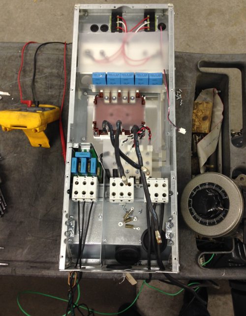 https://www.precision-elec.com/wp-content/uploads/2014/03/hvac-vfd-repair-2.jpg
641
500
Craig Chamberlin
https://www.precision-elec.com/wp-content/uploads/2025/02/Precision-Electric-Logo-TEXT-ONLY-Color-NEW.png
Craig Chamberlin2014-03-05 11:01:332015-07-31 11:41:52HVAC VFD Repair
https://www.precision-elec.com/wp-content/uploads/2014/03/hvac-vfd-repair-2.jpg
641
500
Craig Chamberlin
https://www.precision-elec.com/wp-content/uploads/2025/02/Precision-Electric-Logo-TEXT-ONLY-Color-NEW.png
Craig Chamberlin2014-03-05 11:01:332015-07-31 11:41:52HVAC VFD Repair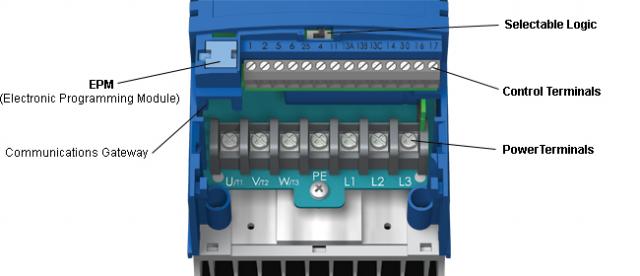 https://www.precision-elec.com/wp-content/uploads/2013/07/vfd-single-phase-to-three-phase.jpg
276
640
Craig Chamberlin
https://www.precision-elec.com/wp-content/uploads/2025/02/Precision-Electric-Logo-TEXT-ONLY-Color-NEW.png
Craig Chamberlin2013-08-05 13:26:442018-02-02 17:29:53VFD Single Phase to Three Phase
https://www.precision-elec.com/wp-content/uploads/2013/07/vfd-single-phase-to-three-phase.jpg
276
640
Craig Chamberlin
https://www.precision-elec.com/wp-content/uploads/2025/02/Precision-Electric-Logo-TEXT-ONLY-Color-NEW.png
Craig Chamberlin2013-08-05 13:26:442018-02-02 17:29:53VFD Single Phase to Three Phase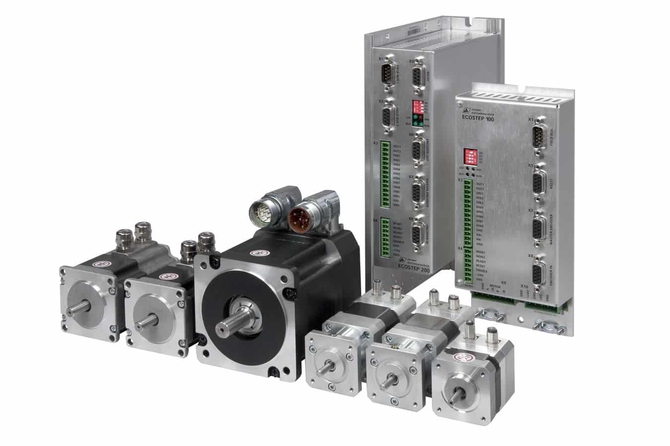 https://www.precision-elec.com/wp-content/uploads/2013/04/brushless-servo-motors-1.jpg
900
1350
Craig Chamberlin
https://www.precision-elec.com/wp-content/uploads/2025/02/Precision-Electric-Logo-TEXT-ONLY-Color-NEW.png
Craig Chamberlin2013-04-24 13:35:352018-02-13 16:02:45Brushless Servo Motors
https://www.precision-elec.com/wp-content/uploads/2013/04/brushless-servo-motors-1.jpg
900
1350
Craig Chamberlin
https://www.precision-elec.com/wp-content/uploads/2025/02/Precision-Electric-Logo-TEXT-ONLY-Color-NEW.png
Craig Chamberlin2013-04-24 13:35:352018-02-13 16:02:45Brushless Servo Motors https://www.precision-elec.com/wp-content/uploads/2013/04/single-phase-to-three-phase-converter.jpg
280
650
Craig Chamberlin
https://www.precision-elec.com/wp-content/uploads/2025/02/Precision-Electric-Logo-TEXT-ONLY-Color-NEW.png
Craig Chamberlin2013-04-09 09:37:352018-02-13 17:05:26Single Phase to Three Phase Converter
https://www.precision-elec.com/wp-content/uploads/2013/01/Step-5-SMVector-Keypad-LCD-Enter-Default-Password_thumb.png
225
401
Craig Chamberlin
https://www.precision-elec.com/wp-content/uploads/2025/02/Precision-Electric-Logo-TEXT-ONLY-Color-NEW.png
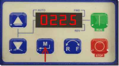
Craig Chamberlin2013-01-10 14:11:332018-02-20 12:40:42What Is The Default Password For An AC Tech SMVector VFD?
https://www.precision-elec.com/wp-content/uploads/2025/02/Precision-Electric-Logo-TEXT-ONLY-Color-NEW.png
0
0
Craig Chamberlin
https://www.precision-elec.com/wp-content/uploads/2025/02/Precision-Electric-Logo-TEXT-ONLY-Color-NEW.png
Craig Chamberlin2012-07-27 12:30:262018-02-01 14:56:14Convert Single Phase to Three Phase
https://www.precision-elec.com/wp-content/uploads/2025/02/Precision-Electric-Logo-TEXT-ONLY-Color-NEW.png
0
0
Craig Chamberlin
https://www.precision-elec.com/wp-content/uploads/2025/02/Precision-Electric-Logo-TEXT-ONLY-Color-NEW.png
Craig Chamberlin2012-01-27 11:58:372017-12-13 13:37:14Lenze AC Tech SMVector Drive Acceleration Time Parameter
https://www.precision-elec.com/wp-content/uploads/2025/02/Precision-Electric-Logo-TEXT-ONLY-Color-NEW.png
0
0
Craig Chamberlin
https://www.precision-elec.com/wp-content/uploads/2025/02/Precision-Electric-Logo-TEXT-ONLY-Color-NEW.png
Craig Chamberlin2011-12-30 13:12:312017-12-12 18:27:47How We Repair Servo Drive Servo Motors Professionally
https://www.precision-elec.com/wp-content/uploads/2025/02/Precision-Electric-Logo-TEXT-ONLY-Color-NEW.png
0
0
Craig Chamberlin
https://www.precision-elec.com/wp-content/uploads/2025/02/Precision-Electric-Logo-TEXT-ONLY-Color-NEW.png
Craig Chamberlin2011-12-30 12:24:482017-12-12 18:26:48How We Repair AC Motor Speed Controllers Or VFDs Professionally
https://www.precision-elec.com/wp-content/uploads/2013/04/single-phase-to-three-phase-converter.jpg
280
650
Craig Chamberlin
https://www.precision-elec.com/wp-content/uploads/2025/02/Precision-Electric-Logo-TEXT-ONLY-Color-NEW.png
Craig Chamberlin2013-04-09 09:37:352018-02-13 17:05:26Single Phase to Three Phase Converter
https://www.precision-elec.com/wp-content/uploads/2013/01/Step-5-SMVector-Keypad-LCD-Enter-Default-Password_thumb.png
225
401
Craig Chamberlin
https://www.precision-elec.com/wp-content/uploads/2025/02/Precision-Electric-Logo-TEXT-ONLY-Color-NEW.png
Craig Chamberlin2013-01-10 14:11:332018-02-20 12:40:42What Is The Default Password For An AC Tech SMVector VFD?
https://www.precision-elec.com/wp-content/uploads/2025/02/Precision-Electric-Logo-TEXT-ONLY-Color-NEW.png
0
0
Craig Chamberlin
https://www.precision-elec.com/wp-content/uploads/2025/02/Precision-Electric-Logo-TEXT-ONLY-Color-NEW.png
Craig Chamberlin2012-07-27 12:30:262018-02-01 14:56:14Convert Single Phase to Three Phase
https://www.precision-elec.com/wp-content/uploads/2025/02/Precision-Electric-Logo-TEXT-ONLY-Color-NEW.png
0
0
Craig Chamberlin
https://www.precision-elec.com/wp-content/uploads/2025/02/Precision-Electric-Logo-TEXT-ONLY-Color-NEW.png
Craig Chamberlin2012-01-27 11:58:372017-12-13 13:37:14Lenze AC Tech SMVector Drive Acceleration Time Parameter
https://www.precision-elec.com/wp-content/uploads/2025/02/Precision-Electric-Logo-TEXT-ONLY-Color-NEW.png
0
0
Craig Chamberlin
https://www.precision-elec.com/wp-content/uploads/2025/02/Precision-Electric-Logo-TEXT-ONLY-Color-NEW.png
Craig Chamberlin2011-12-30 13:12:312017-12-12 18:27:47How We Repair Servo Drive Servo Motors Professionally
https://www.precision-elec.com/wp-content/uploads/2025/02/Precision-Electric-Logo-TEXT-ONLY-Color-NEW.png
0
0
Craig Chamberlin
https://www.precision-elec.com/wp-content/uploads/2025/02/Precision-Electric-Logo-TEXT-ONLY-Color-NEW.png
Craig Chamberlin2011-12-30 12:24:482017-12-12 18:26:48How We Repair AC Motor Speed Controllers Or VFDs Professionally


