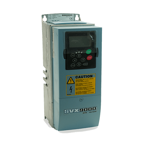
EATON SVX9000 Training Lesson 1: Basic Input Voltage & Motor Wiring – VFDs
About This Video
This video covers wiring the input and output sections of the EATON SVX9000 Variable Frequency Drive. The input voltage will be wired as either single phase or three phase and the output voltage is designed to be wired to AC motors only. It’s also extremely important to note that you should not wire any devices or contactors between the output of the SVX9000 variable frequency drive and the motor, this can result in damaging the motor.


Video Transcript
Hello everyone, my name is Craig Chamberlain with precision electric at precision-elec.com. Your industrial automation service center. Drives, motors, controls, we’ve done it all for over 30 years. If you have any questions or need help make sure you give us a call.
Today’s video is going to cover the sv x 9000 series variable frequency drive. We’re going to cover the wiring of the input voltage and the output voltage to the motor. Also, we’re going to be doing a number of videos on this drive over the next few weeks. If you haven’t seen this drive, well I’d be surprised. There’s a ton of them installed out there and it’s a very popular drive. We get a lot of them in here for repair actually and we’re pretty excited to show you guys some stuff with it. So let’s get started okay.
So the first thing we’re gonna want to do is take off this cover. And that’s just a matter of using a flathead screwdriver and turning counterclockwise and removing it. So that part’s pretty easy. Then when we get underneath, you’ll notice this connector right here. This is essentially our low voltage wiring inputs. We’re not going to be using these just yet, we’ll be doing those in a future video. What we’re mostly concerned with in this video is the actual wiring. Here on the left-hand side is going to be our input voltage. On the right-hand side is going to be our output to the motor. So if I pull up the page in the manual that actually covers this that would be the input voltage wiring or the power wiring on page 15 of the manual. You’ll see L1, L2 and L3 bring your three hots in. And for U, V, and W, that’s going to be your output directly to your motor. Now it’s extremely important that you don’t put anything between the output and the motor itself. Unless it’s like some terminal blocks, for example. But you don’t want anything that can interrupt the connection between the output and the motor itself. So it’s very important to remember because if you interrupt that connection while the drive is running you can actually damage the drive itself.
So on my setup, I essentially have single-phase coming in just because this is a demo unit, and I’m only using single-phase 230. I’m bringing that single-phase in all the way to L1 and l2 and I’m leaving l3 open. I have fused my single-phase input since I have two hot lines I fused each line and if I actually pull up the manual again on the left hand side here, you will see a horsepower rating and this is on page six. And if I go I do a cross reference here for my horsepower rating, I can actually see my recommended fuse sizing, my recommended wire sizing, and even recommended terminal sizes (if want to actually add my wn terminals). So that’s a nice little feature here of the svx manuals. They have all of your recommended fusing and wire sizes right in the manual itself.
So essentially, I have fused this and I brought my hot into my own in L two and now on the output here for U, V, and W, I have this going out to a terminal block and then that terminal block plugs directly into the motor itself. And that’s really all there is to wiring up the input power to your drive. So let’s go ahead and power it up.
So now the only step is to actually apply the input power. And we wait a little bit for the DC caps to charge. Hear the fan kick on. I’m getting an input phase warning – now that was because I said I was only using a single phase input. This is actually a three phase input drive. So that’s why I’m getting the input phase warning and I can actually disable that warning if I wish. And essentially that’s it. That’s how you wire your input voltage.
So now in the next video what we’re going to do is cover the actual startup of the drive. We’re going to go through the basic commissioning. We’re gonna run it and change some basic parameters and essentially get going. If you have any other questions don’t forget to visit our website at precision-elec.com and we’re your automation control service center. Drives, motors, controls, you name it. We’ve done it for over 30 years and we’re pretty much on standby to answer any of your questions. And don’t forget we repair these! We actually have 30 of them at our facility as I speak, because they’re very, very commonly used drives. They’re actually very reliable too! It’s just there’s so many, that there’s a lot of repair work out there for them. So thanks for stopping by and I’ll see you in the next video!


")


