How To Wire A Motor To A Variable Frequency Drive (VFD)
About This Video
This video covers generic motor wiring of a variable frequency drive (VFD). Variable Frequency Drives are pretty simple to wire, but it is only recommend you let a qualified electrician handle any of your wiring needs. It’s also important to adhere to all of your local, nationwide and international safety laws.


Video Transcript
Good morning, Internet!
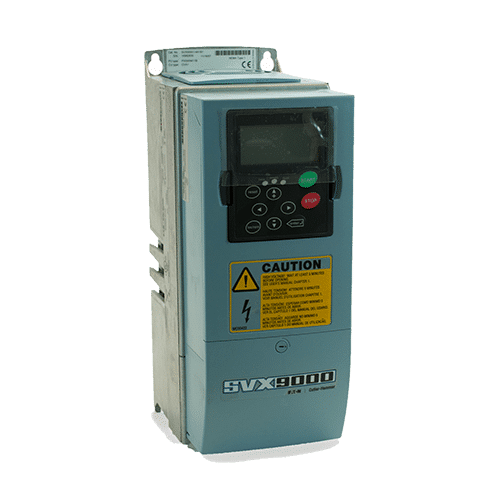
Craig Chamberlain with Precision Electric here at Precision-Elec.com and we’re going to be talking about the SMVector Variable Frequency Drive today.
More importantly, if you don’t have the SMVector this is pretty much a generalized guide on how to wire the electrical wiring or the motor wiring to your variable frequency drive. Now of course, as a disclaimer I have to tell you guys this should only be done by a qualified electrician. Make sure that you’re taking all of the necessary safety precautions so that you do not get hurt or killed. Remember electricity and current can kill you. So make sure you are you are adhering to all the necessary safety requirements.
This whole process really depends on your drive, your motor, and the size of the wire you’re going to be using. Obviously this is a very small example. Your drive could be much larger than this, as well as your motor. So the principles – the basic theory is going to be the same. But it really comes down to the type of equipment you’re using. There is a standard out there for most motors. You have three motor wires typically. That would be U, V and W. In my case they are not labeled. In many cases they don’t have to be phased in a certain way. They can be wired with any of those three wires: U, V, and W. Now depending on how you wire them and how your motor is wired of course, that can affect direction. Many times you can change direction simply by swapping one of the phases of your motor leads. That’s something you want to take into consideration when you’re wiring your motor. If it’s connected to a piece of equipment or to a load, that can be damaged if it runs in the wrong direction. You want to disconnect it from the load before you start connecting things and running them. You want to make sure that you don’t break something, right? That’s just common sense.
The fourth wire here is the ground. Now I’m assuming here that when you look on the nameplate of your motor, you know what the voltage is for your motor. And you’ve matched the voltage with your drive. You’ve also sized your drive correctly. Part of what we do at Precision Electric is we do industrial service repair. We also do basically everything: drive repair, automation, and motor repair. We’re a solutions company; we’re not just a distributor. We obviously sell drives but we’re more on the support side of things. So part of this whole process is if you buy products off of us, you will have our support.
Now if I decided to wire this, I’ve already checked to make sure that I’ve got the right wire size, which I’m going to go over with you real quick. I’ve also made sure that all my motor and everything is disconnected from the load and I’ve also made sure that there’s no power applied to my drive. [Note] any other safety procedures. Your safety is you, right? You are responsible for your safety.
So let me bring up this guide here real quick. If you have a drive, it’s really good to pull up the manual. Right now I have on my screen the variable frequency drive manual. It gives you recommended wire sizes depending on the drive that you’re using. Now what I’m going to do is I’m going to look at the nameplate data here on this drive. It says that the type is an ESV 371 N01 SXB. So what I’m going to do here is I’m going to look for that part number. ESV 371 N01 SXB: And I’m going to go across this table.
Many of these (many, many) drives have this included. If they don’t you’ll probably want to contact the creator of the drive to find out for sure what they recommend you use. But this will give you recommended fusing for your input line voltage. It’ll also give you in this case, the wire size that I want to use. Your wire size is going to be printed on the side of your wire. It’s a minimum recommendation for this particular guide. You can also consult an electrical manual (let me see if I have it here on hand), such as an electrical engineering pocket book. Or, you can look up wire sizing charts to make sure that you’re using the proper wire size for the current draw of your motor. Remember the current draw is the single most important part of it because that’s what generates the heat, and that’s a really big part. You can burn up your wire and you can cause shorts and really damage your equipment if you don’t properly size your wire.
So this guide here on the actual chart tells me that I need a 14 gauge. So then I go through my actual wire here and I don’t know if you guys can see that, because my autofocus is turned off, but I did look and it says 14 AWG (which is 14 gauge). So I am good to go there. So then what I need to do is strip the wire. When you’re stripping your wire you want to make sure that you are stripping it just the right distance to not have any overhang. You also want to make sure that there’s not any insulation that gets tied or tightened underneath the actual screw when you’re tightening down the lug. So what I’m going to do is I’m going to check my distance here by holding my wire very close to the screw, just to kind of get an idea of what my distance is for how I want this. I’m not sure if you guys can see that or not. I haven’t really tested it with this close. So I’ll leave my thumb and finger where I where I want to cut it and then I’ll take that distance, take my wire strippers, and I will cut it at that distance. I’m going to do all three of them the exact same way because the distance should be the same on all of them.
Finally, it’s always important to make sure that you consult your manual on your motor wiring as well because you want to make sure you’re landing it to the right terminals on the drive. So I’m going to scroll to the motor-connection section of my equipment. It says right here on the motor-connection that I need to wire to U, V, and W or T1, T2, and T3. If I look at this, I’ve already got my input voltage which we wired in a previous video. On the left hand side I have U, V and W. I’m actually going to wire these to those particular screws. Now what I usually do is I’ll unscrew them first and I’ll go ahead and put it in. You don’t want any frayed wires. So if you have to twist the wire sometimes to get it in there, get it in there. Then you unscrew it to loosen it, of course. Get it in there as far as you can. Remember, when you’re tightening it you don’t want any wire fraying out from the side. Make sure you strip it correctly. Let me give you an example of how that looks. This is the one I just wired. You can’t see any copper wire popping out of the bottom of it, which is absolutely essential when you’re doing this entire process.
You don’t want any of those wires or the little copper leads or wires actually fraying out from the screw itself because that can cause shorts, and it can also cause loose connections. Secondly, you also want to make sure that your screw is nice and tight. Of course you don’t want to over torque it because if you over torque, it then you can actually damage the connector on the drive. But make sure it is nice and tight, because then you will know for a fact you’re making and maintaining the proper connection. Remember equipment vibrates. So when you’re using screws, if they’re loose or if they’re not tight the vibration of the equipment can cause your screws to come loose. You don’t want that to happen.
I’m going to show you the final result here as soon as I get this last wire in here. As you can see on my print, I’m wiring U, V. and W. Then finally I’m going to wire my ground. Right now my input voltage and my motor voltage are both wired to the same ground. Remember, your ground is ground, so it’s okay to do that. That’s a big part of this. Your wire sizes, as I said earlier, make sure you’re consulting your manual for that as well as running it through the proper conduit. So if you have three wires running into a single conduit, you want to make sure that that conduit isn’t running any low voltage wiring or anything. So here’s my final result. It’s pretty much how it looks. I did as much of it as I could. That puts us at finishing. So that’s it.
If you look at the chart here, what I did is I wired up U, V, and W, and I wired up the motor. So I’m officially running at the proper setup. Now in the next video, I’m going to actually set this motor up in this drive. Like I said, it’s very similar across drives. If you’re in the market for variable frequency drives, or if you’re in the market for industrial repair of any kind, make sure you give us a call. You can reach us at 574-256-1000. Also, check out Precision-Elec.com, where we sell these drives online. We also offer many other brands if they’re not on there. So make sure you give us a call and we’ll see what we can do for you.
Thanks for coming out and I’ll see you guys in the next video.


")


