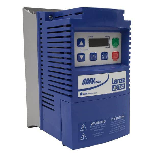
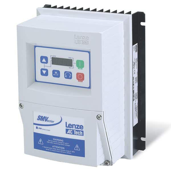
Lenze SMV Training Lesson 10: Feedback Monitoring Of Inputs, Outputs, Voltages, And Current
About This Video
This video covers the Lenze AC Tech SMVector Variable Frequency Drive (VFD) parameters associated with monitoring all of your inputs, outputs, voltages and current. These feedback parameters are critical when troubleshooting your drive because they will give you in depth information on how your drive is seeing your motor and application. This will help immensely with troubleshooting any possible issues you might be having with your drive.
Video Transcript
Hello everyone, this is Craig Chamberlin with Precision-Electric at precision-elec or precision-elec.com. We are your industrial service center, motors, drives, controls, automation, panels, PLCs; you name it we can do it. If you have any questions, feel free to give us a call.
This video in particular is going to cover troubleshooting and feedback from your SMvector variable frequency drive. Now you may have gotten everything set up and it may be running just the way you want it, and maybe you just want to verify that your voltages is good, your current is good, and maybe your analog signals are all set up correctly or perhaps things aren’t quite running the way you intended them to run and you need a little more information in order to determine maybe the cause of that failure or the cause of the problem.
Now this drive actually has a whole set of parameters that will give you almost any kind of feedback you might need to troubleshoot your drive, but there’s one particular area we can’t look at in the program and in the software and we be using a meter for that and that’s your digital inputs. So we’ll do the, the meter at the end of the video, we’ll do the digital input monitoring at the end of the video, but for now let’s dig into the actual parameters and take a look at what we can see.
If you want to follow along in the manual, which we always encourage you to do, it’s actually in section 4.5.7 for Diagnostic Parameters and it’s basically parameter group 500.
Now if I pull up the menu, I can go into parameter group 500, and find 500 will actually give me my fault history. So if I want to look at all of my previous 8 faults, I can actually scroll down through them; in my case they are actually all the same, it’s a low voltage fault because every time I cut power off to the drive, technically it faults.
If I go to 501, I can actually take a look at my software version, not really that critical for most people, unless you want to match your EPM module, which stores some of your program data with an older version, but for the most part they’re all backwards compatible, so when you get a new EPM, or a new drive, it’ll support an older EPM set up.
Let’s go up to 502, drive ID, again not super important. This is more of a software specification.
505, we’ll skip over 503, that’s an internal code. 505 is your DC bus voltage. Now this is actually an important , uh, important value. Your DC bus voltage is actually 1.4 or 1.414 times your input voltage unless you’re actually using a single phase 120, then it’s gonna actually be 230 times 1.414 cause it’s converting 230 volts into DC voltage so that it can re-output 230 volts. The important thing to take away from this, is this value should always be about 1.4 times whatever you’re putting into the drive. So if you’re putting in 1-240 it should be 320. For 480, it should be around 670 and for 600 volts, it’s going to be around, woah let’s see 800? It’s gonna be pretty close to 7-800 volts. So basically do the math, and make sure that that matches, because this means the input section on your drive is at least working properly.
Let’s go to 506, 506 is my motor voltage, right now it’s zero, but if I actually start my motor, let me go back; I can pull 506 up and right now it’s outputting 19 volts, and that is actually normal cause I’m not running my motor at full speed. The drive is designed to output whatever voltage and current is necessary to get you at the speed you want to get. So right now I’m actually running 19 volts, so don’t be scared if it’s not your motor’s rated voltage.
Let’s go to 507, that is your load. That’s a percentage of the rated current of the drive. Right now I’m pulling 34 percent of my drive’s rated current, this may be useful for you if you’re having load issues or perhaps your drive just isn’t running the way you want it to run, and you’re trying to figure out just how much current you are pulling on the motor. So I went up a little bit in my speed, but since my load hasn’t changed my percentage actually doesn’t change, even though I went faster. The load hasn’t changed, cause I haven’t actually put any work on the motor shaft. So that’s a good way to determine if you’re overloading your drive, or at least getting close to the current limit of your drive.
508 is your motor current. This is actually the motored, the uh current that’s going out to the motor itself. So this is different than our drive current, which is a percentage of our total drive capacity. So that was 507, so this is a percentage, 36 percent is of my drive’s capacity. But if I need to know in amps how much load my motor is actually getting, this tells me it’s 0.8 amps. Of course, this isn’t going to be as accurate as an ammeter that you physically put on the output, but it at least gives you a really good idea of how much current you’re putting into your motor at any given moment. And that will change, depending on your load. So you can watch that in real time if you wish.’
Parameter 509 gives you your torque. That’s in a percentage of the rated torque of the drive and the motor. So right now it says it’s only doing 8 percent, which is about right because I’m just spinning the shaft, I don’t have any actual work on it.
Parameter 510, not a whole lot of use to this one, this your rated power consumption in kilowatts, unless you’re calculating your kilowatts-hours and maybe your energy savings, you can use that if you’d like.
512, this is your heat sink temperature. Right now it is at 48 degrees, and that is in degrees Celsius. The maximum range is 150. At the beginning of your drive manual it’ll actually tell you what the maximum operating temperature is for these drives and it is actually 70 degrees Celsius, so I’m well within my operating temperature of the drive. That’s a great way to make sure your environment is cool enough and that the drive, while it’s running is actually staying within tolerance of the heat sink.
520, I’m going to show 0 for this. Oh no, I won’t, actually I programmed that because this is my speed pod input. That’s 0 to 10 volts, I can actually monitor if I got a speed pod wired up, which I do right now, I can turn it up and down. I can actually monitor what that 0 to 10 volt reference is, which is really nice because you can make sure you have your speed pod wired up correctly. If it always shows 10 volts or always shows 0 volts, that typically means you just don’t have it wired correctly.
Parameter 521, this is your 4 to 20 milliamp. Mine’s gonna show 0, cause right now my speedpod is in 0 to 10 volts, but if you have a current input, maybe from a PLC or from a sensor, this is where you’d monitor your currents between 4 and 20 milliamps.
Parameter 522, this one is your TB5 feedback. So this is a TB5 signal, so your digital input signal for, let’s say you’ve got a PID loop set up, for those of you who know what PID loops are, they are for maintaining a constant speed, uh, or a constant flow rate. Maybe you’ve got a set point for pressure or for, uh, water level, this actually lets you monitor that input, that feedback input, for TB5, that Terminal Block 5 down here, which would be a 0 to 10 volt reference, and you can do the same thing for your, on 523, for your analog reference if your PID input uses a 4 to 20 milliamp signal.
We’ve got network feedback on 524. Network feedback, basically it’s got, it lets you monitor what your reference is from whatever network protocol you’ve might have set up, whether that’s devicenet, profinet, profibus.
525 will give you your analog outputs. So if you’ve programmed your analog output, which is 0 to 10 volts, maybe you’re programming it for your current speed, this’ll actually show you whatever voltage is being output to your other device. You can even use your analog output to run a, the speed on a seperate drive. It’s a real popular application, it’s called master-slave.
On 527 this is your actual output frequency. So I may be telling my drive to run 28 point, the 30, I may be able to tell my drive to run 35 Hertz, but until I check my actual frequency, I don’t know what it’s actually running. So right now it’s at 35.1. This is actually really useful if you’re using like a speed pod to control your speed for example, because the speed pod doesn’t tell you what your frequency is. So when you actually check your actual output, you can see what your actual frequency is.
Parameter 528 is your network speed command. This will basically tell you if you are in, uh whatever your speed reference is from whatever network protocol you might be using.
Terminal and Protection status. This one is very confusing and we don’t use it, heh heh. Mostly because we prefer to actually measure our digital inputs the old fashioned way,with a meter, which I will show you shortly.
Let’s go to the keypad status, which will basically tell you that the keypad is functioning correctly, so it turns on all the LEDs just to make sure.
And 540 we’ve got total runtime. Right now I’m only running for 1 minute because I just started it pretty much for this video.
541 is total power on time, which is a little bit longer in my case. 124 hours, so that’s the total lifespan it’s actually been powered on.
And parameter 550 will actually tell you your fault history again. It’s basically the same as parameter 500. So I’m going to go ahead to 550 and it does give me, again, the fault history. Which is good for diagnosing if a fault occurred and the drive shut off and you power it back on you get an idea of what previous faults happened.
So let’s go ahead and monitor the digital inputs, this will give you all the data you need for any kind of data that’s related to the inputs or outputs of drive itself, other than the digital, and next we’re actually gonna go over monitoring those digital inputs so we can troubleshoot at those as well.
Ok, so I’m going to start by actually testing continuity, or making sure there’s an electrical signal going between 4, which is our common, and 13A, 13B, and 13C, those are our 3 digital inputs. Now if you look at the electrical print in the manual it does show those as the programmable inputs. So I’m going to set my meter to measure resistance and if there’s no resistance, it means there’s continuity, if there is resistance it means there’s not. So I’m going to put my black lead on 4, which is my common, and I’m going to put my red lead on 13A. And actually, what it did is it turned on my preset speed, so it actually made continuity, which is kind of funny because normally I’d have to flip the switch to make the continuity. So if I look up here, it says there isn’t any continuity under normal circumstances, but if I flip this switch, I can actually see that continuity take place so now it’s open. I close it again, I apologize now it’s closed, now it’s open, heh heh. I close it now it actually has continuity, there’s no resistance so electricity is flowing. Now if I flip my other switch for 13B, obviously it doesn’t make 13A go high, so I actually have to move my red lead to 13B. I flip the switch, I have continuity, I close it, I lose continuity. That’s really all there is to it. Now while I may trigger that input by doing this, see how I’m doing that, I’m triggering my inputs. I may trigger those inputs, I can still measure continuity while I’m triggering them and that’s really the important thing to take away from this, is that I’m making sure that I have continuity between those digital inputs when I press the appropriate buttons or flip the appropriate switches. And that’s the best way to measure digital inputs, it’s to make sure you have a meter and to check to make sure you have continuity between the two inputs, or the common and whatever your input is. Other than that you do have a relay output between the terminal 16 and 17, I don’t have mine programmed, if I put my leads on it, it says it’s open right now because it’s not programmed. If I wanted to test my relay, usually you can hear it click in when it turns on, but when it clicks in, you should see continuity; so in other words that relay has closed. So that’s another input you can test with your meter. That’s pretty much it.
So that’s how you basically look at all of the feedback from the drive and also how you test all of your digital inputs. This is a great way to at least get started on trying to figure out what’s going on, if there’s something going on with your drive, what’s the root cause of that and it’s also a great way just to verify you have everything set up and wired correctly.
If you have any other questions, of course you can visit our website, give us a call. That’s at precision-elec.com or if you have any other questions related to industrial motors, drives, automation; like I said we are your industrial service center, so pretty much anything related to industrial; business to business, programming, we can do it. So thanks for stopping by, don’t forget to like, share, and subscribe and we’ll see you in the next lesson.

