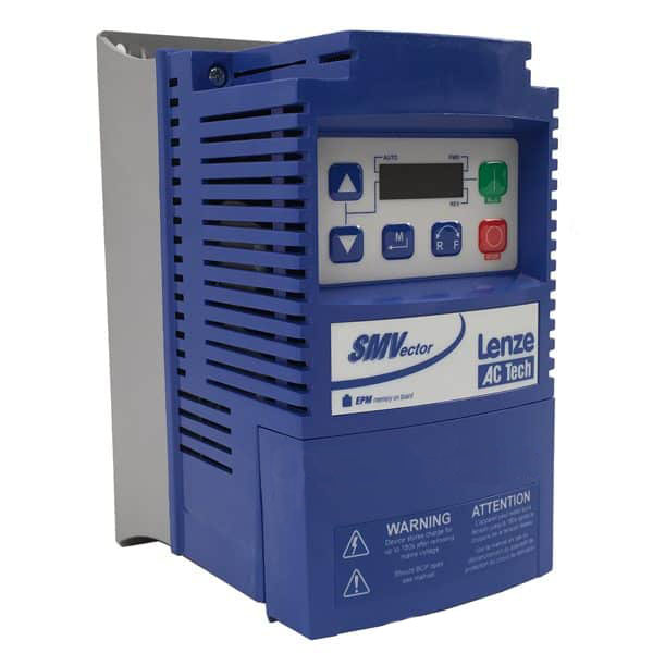
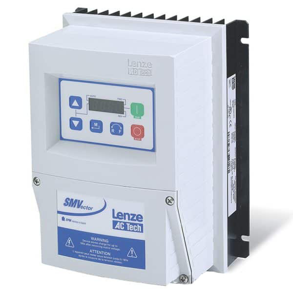
Lenze SMV Training Lesson 12: Basic PID Loop Pump Or Pressure Motor Control – VFDs
About This Video
This video covers how to setup and configure a basic PID Loop for pump or pressure control using the Lenze AC Tech SMVector Variable Frequency Drive (VFD). This is one of the more complex topics covered by the SMV variable frequency drive and it works quite well for maintaining a constant level, flow or pressure on your equipment.
Video Transcript
Hello everyone, this is Craig Chamberlain with Precision Electric at precision-elec.com. We’re your industrial automation service center, drives, motors, automation, PLC’s. You name it, we do it, and have done it for almost 30 years. So make sure you swing by and check us out. Now today’s video, we’re going to be covering an advanced topic for the SM vector variable frequency drive.
The SM vector variable frequency drive is capable of a lot of advanced features. It’s one of the nice things about the drive. It can do very basic applications, but it can also do more advanced ones. In this particular case, we’re going to be doing a PID loop. For those of you who don’t know what a PID loop is is essentially, let’s say you’ve got a pump or an air compressor but for our sake, we’re going to just stick with the pump because water just tends to be easier to work with. Let’s say you’ve got a tank that you want to maintain a certain level of water in at all times or at any given time. If this tank is normally this tall and you want it half-full, let’s say you want to keep it half-full all the time. So if I start to empty the tank, I want my pump or my motor to speed up as I lose more and more water if I get further and further away from my target. I want it to go faster and faster as I get closer to my level or my target level in my tank. I want it to kind of ease into it or kind of slow down a little bit until it hits my halfway point
A PID loop takes a sensor which detects your level it could be a zero to 10 volt signal or a 4 to 20 milliamp signal which tells you how much water is in the tank and the drive monitors that level and it responds accordingly based on speed. So, it either speeds up because it’s really far away from your target or it’s slowing down because it’s getting really close to your target level. It’s the same thing with air compressors. Let’s say you’ve got a target pressure, so as you guys zero to a hundred pounds of air pressure and you want seventy pounds, as you get further and further away from that 70 pounds it’s dropping lower and lower maybe 240 pounds, you want your compressor motor to speed up a lot quicker so that it can start to build up that pressure quicker and get try to get you back to that 70 pounds.
So there are a few elements to this that we’re going to cover. There’s our feedback signal which would be, in our case, show the level of the tank the level of water in the tank and I’m going to be using this speed pot to represent that water level. Right now we’re at five so we’re at fifty percent. So this is a sensor I would have connected to my water tank to show me the actual level of the water and then I also have my set point which I would set at my keypad. so my target so this is my actual level of water and my keypad is like how much water I actually want in
the tank. So I may have this set of fifty or seventy percent of the level of the tank, and lastly, I need a digital input that will tell my drive that I am looking at my sensor for PID control. So I need some way to tell the driveto turn on. I can even use a jumper but we are going to program an input to tell the drive we are in PID control so that it knows to look at this input from your tank or your wire your air compressor wherever whatever you might be.
Maintaining those aren’t your only two applications for PID by the way. You basically need to tell the drive that we’re in PID control. So let’s go ahead and get it wired and programmed and then we’ll show you in action. Okay, so to get started we’re actually going to be looking at section 3.2.3 in our manual for control terminals and we need to install first a jumper between one and four. That’s going to be our drive and able I did put that jumper in there four is our common and I’m in a wire four to one side of my selector switch and on the other side of my selector switch I’m going to wire it into 13 A 13 A. As I had mentioned earlier is a programmable input and this is the input that when I flip my switch, it’s going to close the connection between 4 and 13 A and it’s going to tell my drive after I program it that I’m in PID control.
Now the last part of the wiring is essentially your analog input. So whatever signal wiring you have coming back from your sensor typically it’s only going to be two wires since I’m using a speed pot, I’m using three wires. We’re going to use terminals five and six for your signal. I’m sorry two and five. Let me get that correct two and five for a 0-10 volt signal to will be your common, and five will be your signal. You’ll want to power your actual sensor separately from the drive. You want to have a separate DC power supply. You do not want to power your signal your signal sensor from this drive. It’s a very, very low current power supply and your risk overloading your drive. If you attempt to power your
signal from your sensor from the drive itself so just make sure you don’t use six to power your external sensor. Right now, I said I’m using it because I’m just using a speed pot so there’s no actual power going to the sensor. But you’re just going to bring in two and five – those are your zero to ten volt and if you’re using a 4 to 20 milliamp signal, then you’re not going to use two and five. You’re actually going to use two which is again your common 25 is going to be your 4 to 20 milliamp signal coming from your sensor.
Now those are really the only wiring sections you need set up. So since I’ve got my input wired, I’m going to have to program that first. Let’s start again in our manual. Let’s go to parameter 121. 121 is a programmable input program and for TB 13 a digital input. Right now, it’s set to 0. Here is where I’m going to set my actual auto reference for where I want to do my setpoint. So in other words, I’m telling the drive with parameter 121 what I want to look at for my PID setpoint reference. Now I can get that reference from a network connection, I can get it from a preset, I can get it from a separate analog input, but for our demonstration, we’re just going to get that from our keypad. So we’re actually going to set parameter 121 to 6. So let me press the menu button I’m going to go to 121 and I’m going to set that to 6 I’m going to press ENTER. So that tells the drive when I switch over to 13 a to look at the keypad for my reference.
Now we haven’t turned on the PID yet. We’re going to do that next. Let’s go back to our manual and we’re going to go to parameter 200. Flip through a couple pages as I said before we do everything in the manual. Now I’ve got a few PID modes I can actually use. I’ve got disabled which is default normal acting, basically says that as I get further from my signal speed up the motor, but as I get if I want to have it be reverse acting, I can actually have a have it slowed down as I get further away. It just depends on what my application is in my instance. As my tank gets more and more empty, in other words, I lose more and more water if I get further away from my setpoint. I’m going to want normal acting because I want it to run faster as I get further away. So in other words as I lose more and more water, I don’t want the motor to slow down I wanted to speed up. Now reverse acting would do the opposite of that now.
I can also do normal acting bi-directional which means that if for some reason my signal goes in the opposite direction from my setpoint – in other words, if I overshoot, maybe my tank gets too full and my set points 50 and I get 70 I can actually have the motor run in the opposite direction to empty water. So that’s one option as well, but in my case, I don’t need it to try to empty water. I have a one-way pump I don’t have a bi-directional pump. So I’m still going to set mine to normal acting, so let me go to parameter 200 go up 200 and we’re going to set that to 1 press ENTER and that turns on PID mode. My next parameter I need to set is actually parameter 201. That’s my feedback source and that’s my signal that my actual water levels coming from in my case. Like I said, I’m using a speed pot so I’m going to use this V 0 to 10 volt DC but you want to select whatever your sensor set up for. And again, I press 201 and I set 1 which is 0 to 10 volts DC.
Other than that, I can get a little more customizations in here. I can say I want my PID decimal point to be a little bit further out. I can say I want my PID units to be a little further. I can even in parameter 204 and 205 change my range. Right now by default the SM vector set for 0-100% which is good for my tank. Right, so let’s say my sensor goes to empty to full 0 to 100 will work for me so I can just say 0 to 100 is 0% full to 1% full. But if let’s say I don’t have a 100% on my tank. Let’s say it’s 60 Hertz or 60% or maybe let’s just say sixty gallons maybe I wanted to display gallons. I can have it go from zero to sixty gallons. So I’d set 205 to 60 and 204 to zero. This is real popular setting these ranges is real popular for pressures too because your sensor may be forty pounds to like one hundred and twenty pounds so you can actually set your range or your target range on that. So in my case, I’m actually going to set that 205 back to 100 because I like the 0-100% plus it matches my speed pot which is zero to ten. So that’ll make our demonstration a little cleaner and then that puts us at a complete configuration of our PID loop.
So let’s go ahead and run it. Okay, so the first thing I’m going to do is turn on PID mode now when I flip this switch the screen actually flashed PID and it actually shows a little light in the top left corner for auto which means auto reference keypad. Next, I’m going to actually start my motor notice nothing actually happens. Well, that’s because I actually have my setpoint set at 50 percent and right now my actual tank is 50%. Now let’s say I turn on a valve and I actually start shooting out all the water from my tank and I start to lose pressure well as you can see as I get less and less water in my tank the motor speeds up more and more and if my tank is completely empty it’ll actually run at full speed. Now as that water level continues to build up and gets closer and closer to my target again, it’s going to start slowing down until it finally reaches that set point which in my case was 50%. Now let’s say I want to actually have 70 percent of my tank full. All I need to do is since I set it to auto reference keypad is I can set it to 70 percent instead. Notice that the motor took off right away because it realized that I’m only at 50 percent and now I need to be at 70 percent.
So now the motors going to run as fast as it can depending on how far away this from the signal until it gets closer and closer to that 70% full and that’s really all there is to it. We’ve pretty much set up a complete PID loop and every time my tank empties and every time it starts to fill it’s going to always respond the same way and it’s always going to try to hit that setpoint. Mine set up to start from the keypad. So I press the start button here first to actually start the motor. You may have a start push button again all that set. In earlier videos, we talked about basic start/stop control and also when I turn this off, since I’m no longer doing an auto reference key bad and P and PID control, it’s actually going to drop to whatever my default speed was at parameter 101 – which was just my standard keypad control for speed control. So I can actually switch between, it’s kind of cool; I can actually switch between normal like this is my manual override let’s say for some reason my sensor
started my sensor broke and I can’t maintain that water level anymore. So I can just actually shut this off and I’m in manual mode. Now I can just run it. run the pump as fast as I want it and then just press the stop button when I’m done, see what I mean? Then when I get my sensor back up and running, I can turn my PID control on again turn on the drive and it’s going to attempt to maintain C if once my levels down it’ll run back in PID control again. So you can actually set it up to switch between manual control and PID control very popular for water and pump applications because there’s a lot of instances where you just for some reason need to override and run your pump manually.
So that’s all there is to this video essentially that’s how you set up a PID control for. In this case, we just did a generic one and I use this as my feedback sensor. But again, pumps pressure pretty much wire tensioners. In other words, if you need to maintain a certain tension or a lot of applications use this kind of idea. That’s why they just call it PID. But essentially, any kind of application where you have some kind of a feedback telling the drive I need to hit this target and you have to have it speed up or slow down as it gets close to it will fit for a PID control application.
If you have any questions at all, we’ve been doing this for well over 30 years. We are Precision Electric, your industrial automation service center, drives, motors, controls, automation, PLC’s. We pretty much do it all. We have done it all for about 30 years,like I said, in a 300 mile radius of where we are, and we also do nationwide. So if you have any questions, feel free to give us a call and we’ll get you taken care of. Thanks for stopping by.
