Lenze SMV Training Lesson 3: Basic Speed Potentiometer Wiring & Setup – Variable Frequency Drives
About This Video
This video will cover the complete wiring and parameter programming setup of a speed potentiometer on the Lenze / AC Tech variable frequency drive. This process is quite simple and it offers a great option for people who are interested in using a speed potentiometer for setting their speeds other than the standard keypad.
Video Transcript
Hello everyone,
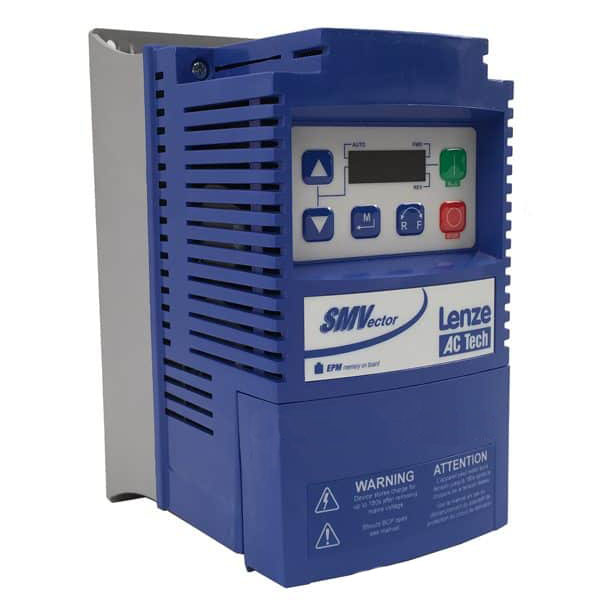
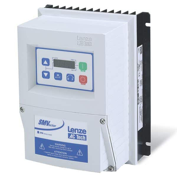
My name is Craig Chamberlain with Precision Electric, and we are doing another video on the SMVector Variable Frequency Drive, which is one of our most popular drives at our web store at precision-elec.com.
We’re not just distributors, we’re integrators. We’ve used and installed these drives locally for over 30 years and now we do it all nationwide. We don’t do field work nationwide but we will support you.
Today’s video is going to cover the speed potentiometer. For those of you who don’t know what a speed potentiometer is, it’s basically like one of these knobs that you can turn to adjust your speed. What we want to do is wire this knob to the drive so that we can adjust our speed up and down and essentially use this instead of the keypad. They’re very popular for most machines because [for] most machines, you don’t want to have to open up a cabinet door and use the up and down arrows on the keypad every time you want to use it. Not to mention these are really nice if your operators like trying to look at a machine and adjust the speed and they don’t have to hold down a button or press a button to keep looking at it. This will allow them to kind of just eyeball it and turn it at the same time. Thats another real popular reason people use these.
The wiring for this is actually pretty easy. All speed potentiometers have the same leads. In other words you’re going to connect the same amount of wires. Were going to connect three wires to it. But they’re all a little different, so depending on the speed potentiometer you have you will need to locate the actual location of each of these three sections we’re going to cover. This is a standard 3 wire for a speed potentiometer. You can use 3 black wires they don’t have to be color-coded. But typically it’s recommended to use color-coded because if somebody’s troubleshooting the speed potentiometer, or the speed pot for short, it’s a lot easier if the color codes are matching where they’re supposed to go.
So black typically is wired to the common on your speed pot, red is typically wired to the hot on your speed pot, and the white is typically wired to the signal of your speed pot. The signal on this adjusts from 0 to 10 volts as you turn the knob, and that tells the drive what speed to go between that operating voltage. Now if you want to pull up the manual, which I always recommend to have the manual, you can actually see the wiring of the speed pot right on page 21 of my manual. There may be a revision so maybe plus or minus one page by the time you watch this video. But you’ll see that there’s a 2K to 10K wiring that shows Terminal 2 as your common, Terminal 5 as your A in, or your analog input, so that’s your signal wire, and then +10 volts which is your hot, and that’s how we’re going to wire it. So let me go ahead and show you how to do that right now.
This section right here on your drive is known as the terminal strip. The first thing you need to know is any time you’re going to use this terminal strip, whether it’s for start/stop control or for a speed pot in our case, you need to actually put a jumper between terminals 1 & 4. That’s your drive enable. Without those two you can never do anything with your terminal strip as far as actually starting, stopping or changing the speed. It’s a safety requirement. That’s also a good place to wire a stop push button or maybe even an E stop because once you actually open that connection the drive is going to shut off no matter what you’re doing. Now as I said before, we’re going to use terminals 2, 5 & 6. In the manual Terminal 2 is my common. As I said earlier we use black for the common. So I’m going to go ahead and put black into Terminal 2. It’s a small wire so sometimes they got to get wiggled in there. Then we tighten it. Don’t over tighten it because you can actually strip out the screws which is never good. The second wire is actually Terminal 5 and that is actually the signal wire in the manual. As we said before our white wire is our signal wire so let me go ahead and get that in there and wire that as well. Sometimes you got to twist the wire to make sure it’s nice and small so that it fits. There we go. Then again tighten it, but not too much. Now for the last wire it is actually Terminal six and that is our hot wire, and we’re going to use the red. Here we go – tighten it. Pull on them a little bit. Tug on them just to make sure they’re tight. That’s pretty much all there is to the wiring portion of it.
After we do the wiring then we have to change one parameter and that’s up here at the keypad. In order to bring up our parameters we have to press this M button. Now we got to go to P101 and press the M button again. By default it’s set to look at the keypad which is 00 for our speed. We’re actually going to tell it instead to look at our speed pot which is 0 to 10 volts and press M. That basically tells the drive to look at our terminal strip for our speed instead of a keypad. Once you set that setting then the up and down arrow keys will not work anymore for running your drive. After you’ve wired it, essentially that’s it.
We can go right back over to our power and turn it on. Mine was already turned on when I was wiring it which is usually not something you want to do – you want to make sure that you completely cut off all your input power to the drive before you do any wiring. I was mostly doing that just for demonstration purposes. After that we can just use our standard start/stop control, which right now mine is set up for the keypad. And I press the start button. Since my speed is at zero it’s not doing anything. But now if I try to use the arrows here to do my speed, I get an ERR message, which means error because it’s no longer you looking at the keypad in order to turn on my speed or turn up my speed. Now it’s looking at the speed pot, so turning up my speed now is just a matter of turning the knob. It does follow me pretty close because my acceleration and deceleration times are really, really fast. So I can actually extend those out. In other words if this is speeding up or slowing down too fast I can actually go in there and adjust parameters 104 and 105 to extend that out (if I wanted to take more time between my speeds). But these are great. Like I said earlier in the video, if your operators are looking at a piece of equipment and they’re trying to slowly adjust it, they don’t need to worry about pressing a button. They can kind of dial it in right where they want it and kind of say all right we’re good to go.
So that’s pretty much all there is to this video. That’s how you wire a speed potentiometer to the SMVector Variable Frequency Drive. Remember we sell all of these drives as well as motors now at our site. All of our prices include technical support. We are integrators – like I said so we’ve been doing this a long time. So don’t hesitate to call. We will be more than happy to help out.

