Lenze SMV Training Lesson 4: Basic Start Stop Pushbutton Control Wiring & Programming – Variable Frequency Drives
About This Video
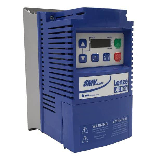
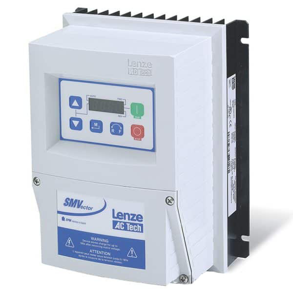
This video will cover the complete wiring and parameter programming setup of a start, stop pushbutton control panel on the Lenze / AC Tech variable frequency drive. This process is quite simple and it offers a great option for people who are interested in using a speed start and stop pushbuttons for controlling their drive instead of the standard keypad.
Video Transcript
Hello everyone,
This is Craig Chamberlain with Precision Electric at precision-elec.com
Today we’re going to talk about the SMVector Variable Frequency Drive and how to wire it with a two button start/stop control. This is a real common method for actually wiring drives. It’s probably the most common for wiring drives – so that you can start them from a separate push-button panel. Now the drives themselves the SMVector Drives can actually run right off the keypad right out of the box. So you can run it off the keypad if you’d like or you can remote run them from a remote keypad. They make those as well which is a separate accessory. But if you wanted to have a separate hardwired push-button start/stop, this is the method you’re going to use to wire it.
Now it’s not that complicated, but the first thing we need to do is open up our manual – this is what I always recommend to people. Any time you watch any of our videos we’re going to be going through the manual. Any time you call our company for technical support we’re going to ask that you open up your manual. The manual has basically everything you can think of for configuring your drive in almost any way possible. The page I’m looking at first is going to be for Parameters 121 through 124. On my manual its page 32, if a newer revision of the manuals come out, it may be a different page for you at this point. But there is a small note section underneath and it has three different little prints on it.
For the first one we’re going to use the middle print, which is a start forward / start reverse wiring diagram. It shows that we wire our stop button, which in this case is this button, through a normally closed contact. This means that when the buttons like this – not pushed in, electricity flows through it. When I push it in, electricity stops flowing through it. It tells us to run our forward, and in this case our reverse – I’ve made it the orange button – through a normally open. So in other words right now electricity is not flowing through this, but when I press it down, electricity will flow through it. The normally open / normally closed part is actually on the back of the contacts of whatever button you have. Usually they label them NO or NC. So that’ll tell you which contact or which part of the contact block to wire through. So after that we’re going to make a small program change and we’ll be done. So let me go ahead and show you how I wired this thing up and then we’ll get it running.
So I have terminals 1, 4, 13A and 13B. Those are the main terminals that are actually showing on the print that we were looking at. Ignore my wire numbers. I just have those from my own reference for my control panel. Yours may be different. But essentially 4 is our common, which means we’re going to wire 4 to one side of our stop button on the normally closed contact. We’re also going to wire 4 to one side of our forward button and one side of our reverse button on the normally open contacts. So 4 is actually commonly shared between all 3 buttons. On the other side of our stop button, this electricity is going to flow through there. On the other side of our stop button, it’s going to come back and we’re going to wire that to 1. That’s our drive enable. Remember this is a normally closed contact which means electricity is constantly flowing between 4 & 1 until we press the stop button.
Once we press the stop button it opens up that contact and the drive disables. 4 then goes out to the side of our forward button, the normally open side of our forward button, and then it comes back on the other side of that normally open button to 13A. 13A we’re going to program for start forward. I’ll do that here momentarily. 4 also goes to the front side of our reverse button on the normally open contact. Then it comes back from the other side of that normally open reverse button to 13B, which we will program for start reverse. Let’s go ahead and program it and that’s pretty easy to do as well. If you press the menu button on your drive it usually defaults a parameter 100, and that’s the first one we want to make sure you have set to terminal strip. If this is set to 00, that means it’ll actually run your start/stop from your keypad. If we want the drive to look at our terminal strip down here, we want to make sure we set this to 01, otherwise our push buttons will never work. Once you’ve set it to 01 just press that M or menu button again. It’ll say stop – that means you’ve set it. I’m going to press it again and I’m actually going to program my forward and my reverse now. So I’m going to go up to Parameter 121. This programs 13A. Right now I have it set to 11 and that’s actually where I want to set it. The default is zero. So I’m going to set it to 11 which means start forward. This means if there’s a momentary connection between 4 and 13A, start running forward. And I say momentary because that’s important. The momentary occurs because that push button – as soon as you push it in the electricity is going to flow and as soon as you release the button it’s going to stop flowing. So when we program that to start forward it doesn’t care if it stops flowing. It just looks for that rising edge of the electricity. Next we’re going to go to Parameter 122. This one needs to be set to 12 which is start reverse, and the concept of the rising edge works the exact same for 13B as well. So let’s go ahead and run it.
As I said before this is my forward button, this is my stop button and this is my reverse button. Now if I press in my forward button the motor starts running forward. And it runs forward at whatever speed I have it set to. Right now I’ve got my speed set up for my speed pot – so I can turn it up and down as I want. By default its set to the keypad, so I can actually turn it up and down to the keypad if it’s set up right out of the box to do that. My second option is my stop button that we wired – stops when I press it. The third one I wired is the reverse. You may or may not have seen that but it did go in the opposite direction. In fact while it’s running in reverse I can press forward and I’ll actually slow to a stop and then go back into reverse. Again you can change the speed at any time. If you want to find out how to do the speed [or] how to wire a speed pot, that’s actually in a previous video that we’ve done already. So go ahead and check out that video and it’ll show you how to wire that and program it as well.
But that’s pretty much all there is to it. That’s how you wire your two wire start/stop control. They call it a two wire because usually you only need two wires to run forward. We added that third wire for the reverse. But typically it’s just a forward and stop on a two wire/start stop control. If you have any other questions we sell these Variable Frequency Drives and more at our website at Precision-Elec.com. We are a full industrial service center. We don’t just sell drives, we do full automation, controls, panel building, and fabrication. We have a whole team of engineers who have been doing this for over 30 years. We’ll be more than happy to help you with any problems you might have.
So thanks for stopping by and don’t forget to Like, Share, and Subscribe. We’ll see you in the next video.
