Lenze SMV Training Lesson 5: Basic Start Stop Selector Switch Control Wiring & Programming – Variable Frequency Drives
About This Video
This video will cover the complete wiring and parameter programming setup of a start, stop switch integrated into a control panel on the Lenze / AC Tech variable frequency drive. This process is quite simple and it offers a great option for people who are interested in using a start and stop switch for controlling their drive instead of the standard keypad.
Video Transcription
Hello everyone,
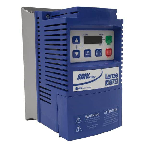
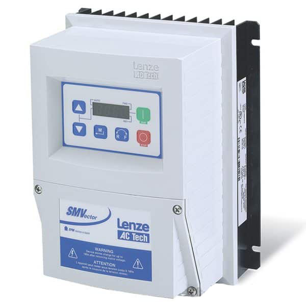
This is Craig Chamberlain with Precision Electric, and we’re bringing another video to you today on the SMVector Variable Frequency Drive.
This particular drive is one of our most popular, and today’s video is going to go over the wiring of selector switches for your start/stop control, instead of push buttons. In a previous video, actually the previous video, we showed you how to wire the two push buttons for your forward and reverse and wire the stop for stopping it at any point in time. Nice thing about using a selector switch instead is this switch is all you need. You don’t need any of the buttons. This is a 3-way selector switch, which allows me to actually run it in forward, reverse, and stop. So this one switch can handle all three tasks – so that’s one of the major advantages of it. Now we’re not just a drive distributor. We do sell these drives, but we are an automation service center so make sure you check us out. We do full fabrication, panel fabrication, automation, controls and basically anything you can think of in the industrial world, we can do it or we have the people who can do it.
So let’s go ahead and get started. As always I’ll have you open up the manual. We will actually be working in the same section of the manual we did in the previous video. And that is in Section 4.5.2. On mine it’s on page 31. It is for the programmable inputs on the drive and we’re going to be programming these inputs for the selector switch. There are a couple prints at the bottom of that section for Parameters 121 through 124. The one we’re looking at is the one on the far left for run forward and run reverse with selector switches. Essentially the wiring is very similar to what we did before except for we no longer need to wire a stop button between our 1 and 4, which is our common and our drive enable. We basically leave the drive enabled all the time and we let the selector switch determine when we go forward and when we go reverse. Now you can optionally wire an E-stop in there if you’d like. That way if you hit it, it will disable the drive. Typically we have E-stops to drop the input voltage though, just for security. But if for some reason you’re doing like a ramping E-stop you may want to wire it between 1 and 4. For the sake of this demonstration we’re just going to leave that jumper.
So let’s go ahead and get it wired and programmed and then I will show you it running. The first part I want to show you is this jumper that I talked about. It is on the print on that section 4.3.2 diagram. The jumper is between 1 and 4. This is our drive enable. Now in order for the drive to run in Terminal Strip Control you have to have this enable closed. In the previous video we actually had a stop button that had a normally closed contact between those, but we no longer need a stop button for our selector switch control. You’ll see why here in a moment. But when we take the selector switch off of the run it’ll automatically stop.
Now terminal 4s are common so we also need to wire terminal 4 to the other side of our selector switch, for both the forward selector switch and the reverse selector switch sections of the terminal block. Now mine is basically a 3-pull selector switch or a 3-way selector switch. I am able to wire this particular wire to that one selector switch in two different areas to get two normally open contacts on the selector switch. Depending on the selector switch you have you may need to have two different selector switches, but since mine is a 3-way selector switch I only had to have one wire going to that block on the selector switch itself. On the other side of that block on my selector switch, I have the forward section (which is turning to the right) coming in to 13A, which is our programmable input -which we will be programming for run forward. On the other side of my normally open contact on the third side of my selector switch, I have it coming into 13B – which I will be programming for run reverse.
Essentially when I flip my switch one way this will go to one side of my block out of common. Then electricity will flow through to 13A. Then when I flip the switch to the other side, electricity will flow from 4 to 13B. You may need to use your meter in order to find out which normally open and normally closed parts of your block are on your selector switch to wire it successfully. Again the print is actually right there in that section. You can look at look it over if you’d like. So let’s go ahead and program it.
First thing we need to do is press the menu button and go down to parameter 100 just to verify that we are in Terminal Strip Control. It’s got to be set to 01. If it’s not set to 01, then it’s not in Terminal Strip Control. If it’s set to 00, its in keypad control – which means you can only start and stop it from the keypad. I’m going to set it to 1 and press the menu button again. Then I’m going to press the menu button a third time to bring up the parameters again and I’m going to go up to Parameter 121. Now this is the parameter that programs this 13A input. I’m going to set this to 13 which actually means start forward. Let me let me double check that.
Nope, it’s run forward. There’s a difference between those two. Let me let me point that out – when you’re using push buttons you want to set that to start forward which is 11, which waits for a momentary connection of electricity. 13, or run forward, requires that electricity is constantly flowing between 4 and 13A for it to keep running forward. That’s how when we turn off the selector switch the drive will turn off. So we’re going to do the same thing for 13B – that’s Parameter 122. We’re going to set that to 14 which is run reverse. So as long as electricity is flowing between 4 and 13B it’ll be running in reverse. Once we open up that switch it’ll stop. So let’s go ahead and run it.
So as I said before this is a 3-way selector switch, which means right now it’s in the center state, which means both my forward and reverse are actually open. So no electricity is flowing to 13A or B. Now if I flip it forward it closes the contact between 4 and 13A, and it runs forward. I can go back to my middle state which opens it. Remember you have to maintain the electricity the way we programmed it with the run forward / run reverse. Since it’s no longer got that connection it stops. So let me go the other way. This will actually run it in reverse because the electricity is now being maintained between 4 and 13B. That’s how we programmed it. So everything’s working great. One nice thing about selector switches as well is if I have it in forward, I can switch it right over to reverse and it’ll kick right in. That’s just how the drives work. They’re designed to be able to turn from forward to reverse at any point in time and it’ll use your accel and decel times you have programmed.
So that’s all there is to this video. That’s how you wire a forward and reverse selector switch to your drive. Again, thank you for stopping by. Don’t forget to check out our website at Precision-elec.com. We do everything for your industrial, electronics and motor service center. We have full-blown electrical panels fabrication, we have programming of automation and PLC’s servos, we do full servo repair, drive repair, you name it. So thanks for stopping by.
Don’t forget to Like, Share and Subscribe and we’ll see you in the next video.
