Description
<p class="wp-block-yoast-seo-estimated-reading-time yoast-reading-time__wrapper"><span class="yoast-reading-time__icon"><svg aria-hidden="true" data-icon="clock" fill="none" focusable="false" height="20" role="img" stroke="currentColor" style="display:inline-block;vertical-align:-0.1em" viewbox="0 0 24 24" width="20" xmlns="http://www.w3.org/2000/svg"><path d="M12 8v4l3 3m6-3a9 9 0 11-18 0 9 9 0 0118 0z" stroke-linecap="round" stroke-linejoin="round" stroke-width="2"></path></svg></span><span class="yoast-reading-time__spacer" style="display:inline-block;width:1em"></span><span class="yoast-reading-time__descriptive-text">Estimated reading time: </span><span class="yoast-reading-time__reading-time">13</span><span class="yoast-reading-time__time-unit"> minutes</span></p>
<!-- wp:heading -->
<h2 class="wp-block-heading" id="introduction-the-silent-threat-to-your">Introduction: The Silent Threat to Your VFD Controlled Motors</h2>
<!-- /wp:heading -->
<!-- wp:paragraph -->
<p><a href="https://www.precision-elec.com/variable-frequency-drives-vfds-guide/" target="_blank" rel="noopener">Variable Frequency Drives</a> (VFDs) are cornerstones of modern industry, offering unparalleled energy savings and precise process control. However, a hidden electrical phenomenon often undermines these benefits, leading to premature motor failure that can cause costly, unplanned downtime. The very technology that makes VFDs so efficient—the rapid Insulated Gate Bi-polar Transistor (IGBT) switching—creates high-frequency voltage pulses that demand effective DV-DT motor protection. Consequently, without proper mitigation, these pulses can silently degrade the motors you rely on, turning a key asset into a recurring liability.</p>
<!-- /wp:paragraph -->
<!-- wp:paragraph -->
<p>This destructive process is known as the Reflective Wave Phenomenon. When a <a href="https://www.precision-elec.com/vfd-guide-industrial-efficiency/" rel="noopener" target="_blank">VFD</a> sends a rapid voltage pulse down a long motor lead, the impedance mismatch between the cable and the motor causes a portion of that pulse to reflect back toward the drive. This reflected wave then adds to subsequent outgoing pulses, creating voltage overshoots at the motor terminals that can easily be double the drive's DC bus voltage. For instance, on a common 480V system, these spikes can exceed 1,200 volts, placing extreme stress on the motor's internal components, especially as motor lead lengths increase.</p>
<!-- /wp:paragraph -->
<!-- wp:paragraph -->
<p>Ultimately, these repetitive high-voltage spikes attack the most vulnerable part of the system: the motor's winding insulation. Standard motor insulation, particularly in motors not specifically designed to NEMA MG-1 Part 31 standards, cannot withstand this electrical stress indefinitely, which leads to dielectric breakdown and short-circuiting. In other words, the insulation fails, causing a catastrophic motor burnout. The definitive solution is to install a TCI V1K motor protection filter DV-DT output filter, a device engineered to absorb these reflections and limit the voltage overshoot, thereby safeguarding the motor and extending its operational lifespan significantly.</p>
<!-- /wp:paragraph -->
<!-- wp:heading -->
<h2 class="wp-block-heading" id="what-is-high-dvdt-and-the">What Is High DV-DT and the VFD Reflective Wave Phenomenon?</h2>
<!-- /wp:heading -->
<!-- wp:paragraph -->
<p>Modern Variable Frequency Drives (VFDs) utilize Insulated Gate Bi-polar Transistors (IGBTs) for their rapid and efficient switching capabilities. However, this high-speed switching creates an unintended consequence known as high DV-DT, which signifies a very rapid rate of voltage change over time. When dealing with long motor leads, this phenomenon necessitates a robust VFD output filter to protect the motor. In short, this high DV-DT is the root cause of the damaging reflective wave phenomenon that can significantly shorten the operational life of a motor.</p>
<!-- /wp:paragraph -->
<!-- wp:paragraph -->
<p>The fast-rising voltage pulses generated by the VFD’s IGBTs travel down the motor cables toward the motor. When these pulses reach the motor, an impedance mismatch between the cable and the motor stator causes a portion of the pulse energy to be reflected back towards the drive. According to research from <a href="https://www.eaton.com/content/dam/eaton/products/industrial-controls-drives-automation-sensors/variable-frequency-drives/vfd-output-filters-wp040003en.pdf" rel="noopener" target="_blank">Eaton VFD Output Filters</a>, this reflected wave can combine with subsequent incoming pulses. Consequently, this superposition can create voltage spikes at the motor terminals that are nearly double the VFD’s DC bus voltage.</p>
<!-- /wp:paragraph -->
<!-- wp:paragraph -->
<p>This repeated exposure to high-voltage spikes places immense stress on the motor’s winding insulation system. For instance, the first turn of the motor winding bears the brunt of this overvoltage stress. In other words, the insulation can quickly degrade, leading to dielectric breakdown, arcing between windings, and ultimately, a catastrophic motor failure. Industry standards, such as those outlined by <a href="https://www.nema.org/Standards/view/mg-1-motors-and-generators" target="_blank" rel="noopener">NEMA in MG-1 Part 31</a>, define the voltage withstand capability of standard motors, and these reflective wave peaks frequently exceed those limits. Therefore, implementing a DV-DT motor protection solution, as detailed by manufacturers like <a href="https://www.transcoil.com/" target="_blank" rel="noopener">TCI (Trans-Coil, Inc.)</a>, is critical for reliability.</p>
<!-- /wp:paragraph -->
<!-- wp:heading -->
<h2 class="wp-block-heading" id="how-vfd-output-damages-motor-insulation">Why Standard VFD Installations Risk Premature Motor Failure</h2>
<!-- /wp:heading -->
<!-- wp:image {"id":264935,"sizeSlug":"large","linkDestination":"none"} -->
<figure class="wp-block-image size-large"><img src="https://www.precision-elec.com/wp-content/uploads/2025/09/vfd-motor-damage-tci-v1k-dv-dt-output-filter.png" alt="Diagram of a TCI V1K motor protection filter dv-dt output filter blocking harmful voltage spikes traveling from a VFD to a..." class="wp-image-264935" title="How the TCI V1K dV/dt Output Filter Protects VFD-Controlled Motors"/><figcaption class="wp-element-caption"><p>VFDs can create a ‘silent threat’ of high-frequency voltage spikes that degrade motor insulation. This illustration shows how a DV-DT output filter neutralizes that threat, ensuring the motor’s longevity and reliability.</p><br></figcaption></figure>
<!-- /wp:image -->
<!-- wp:paragraph -->
<p>Many standard VFD installations create a significant risk of motor damage if they lack a proper VFD output filter. The core of the issue lies in the very nature of a VFD's output, which is not a smooth sine wave but a series of high-frequency voltage pulses generated by Insulated Gate Bi-polar Transistors (IGBTs). This rapid, high-frequency switching creates a condition known as high DV-DT or a high rate of change in voltage over time. Consequently, without mitigation, this electrical stress can lead to the premature breakdown of motor components, long before their expected service life.</p>
<!-- /wp:paragraph -->
<!-- wp:paragraph -->
<p>This high DV-DT is particularly damaging when long cable lengths exist between the drive and the motor, a common scenario in industrial facilities. Specifically, the high-frequency pulses travel down the cable and reflect off the motor's impedance, creating the VFD Reflective Wave Phenomenon. This phenomenon can effectively double the VFD's bus voltage at the motor terminals, subjecting the motor winding insulation to repeated overvoltage stress. In fact, a standard 480V drive can produce spikes well over 1,000V, far exceeding the dielectric strength of typical motor insulation as specified by standards like <a href="https://www.nema.org/Standards/view/MG-1-2021" target="_blank" rel="noopener">NEMA MG 1-2021</a>.</p>
<!-- /wp:paragraph -->
<!-- wp:paragraph -->
<p>Ultimately, this repeated electrical stress degrades the motor's stator winding insulation, leading to pinhole shorts and eventual phase-to-phase or phase-to-ground faults. The result is motor failure, unplanned downtime, and significant replacement costs. According to industry experts at <a href="https://www.cfindustrialsolutions.com/vfd-resources/vfd-output-filters/" target="_blank" rel="noopener">C&F Industrial</a>, this is one of the most common, yet preventable, causes of VFD-related motor failures. Therefore, implementing a DV-DT motor protection solution, such as a TCI V1K motor protection filter DV-DT output filter, is not an optional accessory but a critical component for ensuring long-term system reliability and protecting valuable motor assets. Proper analysis and filter selection are key, as outlined in technical guides from manufacturers like <a href="https://www.transcoil.com/-/media/Project/TCI/TCI/TCI-Documents/H5N/Brochures/H5N-V1K-BR001-EN-A-BR.pdf" target="_blank" rel="noopener">Transcoil H5N Brochure</a>.</p>
<!-- /wp:paragraph -->
<!-- wp:heading -->
<h2 class="wp-block-heading" id="how-the-tci-v1k-motor-protection">How the TCI V1K Motor Protection Filter DV-DT Output Filter Provides a Solution</h2>
<!-- /wp:heading -->
<!-- wp:paragraph -->
<p>The TCI V1K series filter directly counteracts the destructive VFD reflective wave by functioning as a high-performance VFD output filter. Specifically, this device is engineered to slow the rate of voltage rise (DV-DT) produced by the fast switching of a drive's Insulated Gate Bi-polar Transistors (IGBTs). By inserting this impedance between the drive and the motor, the filter effectively dampens the voltage overshoots at the motor terminals. This action prevents the peak voltage from reaching levels that could compromise the motor’s internal components and lead to premature failure.</p>
<!-- /wp:paragraph -->
<!-- wp:paragraph -->
<p>In essence, the TCI V1K filter operates as a tuned low-pass circuit, smoothing the harsh square-wave PWM output into a more motor-friendly waveform. This conditioning is crucial for protecting the motor winding insulation from premature dielectric breakdown caused by repetitive high-voltage spikes. In other words, it ensures the drive’s output complies with the stringent requirements outlined by industry standards for motor protection. For instance, as detailed in guidelines from the <a href="https://www.easa.com/resources/resource-type/easa-data/tech-notes/nema-mg-1-2016-and-vfd-powered-motors" target="_blank" rel="noopener">Electrical Apparatus Service Association</a> on NEMA MG-1, controlling DV-DT is a mandatory step for ensuring motor reliability on VFD power.</p>
<!-- /wp:paragraph -->
<!-- wp:paragraph -->
<p>Ultimately, the primary benefit of installing a TCI V1K motor protection filter DV-DT output filter is a significant increase in motor lifespan and system reliability. By providing robust DV-DT motor protection, the filter serves as an essential long lead VFD solution, where long cable runs greatly amplify the reflective wave phenomenon. Moreover, managing the voltage rise time can also mitigate other harmonic-related problems, including EMI/RFI noise and damaging bearing currents, a topic covered by industry resources like <a href="https://www.machinerylubrication.com/Read/30931/vfd-bearing-currents" target="_blank" rel="noopener">Machinery Lubrication</a>. As confirmed by manufacturers like <a href="https://www.transcoil.com/products/v1k/" target="_blank" rel="noopener">Trans-Coil, Inc.</a>, implementing this type of drive output choke is a best practice for safeguarding critical motor assets from electrical stress.</p>
<!-- /wp:paragraph -->
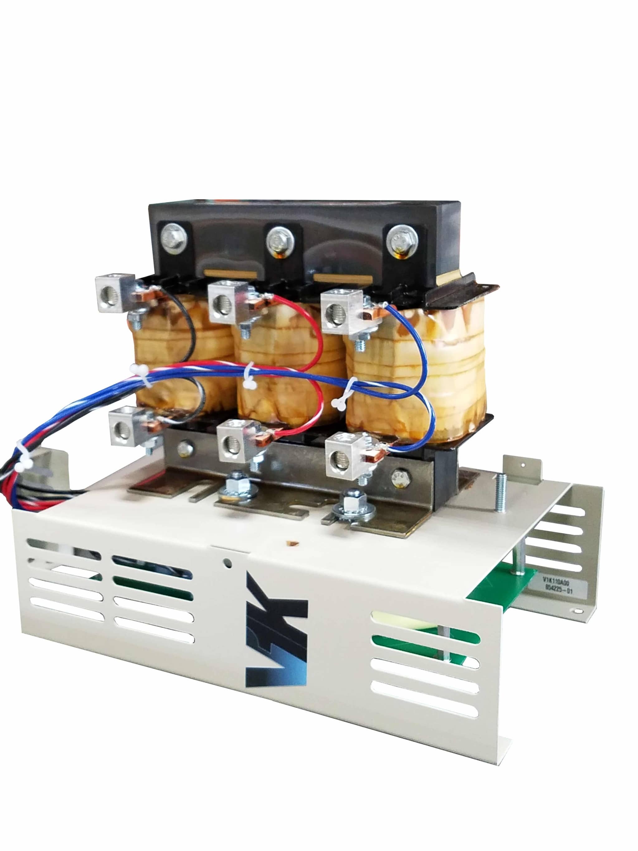
<!-- wp:heading -->
<h2 class="wp-block-heading" id="technical-deep-dive-features-and-operation">Technical Deep Dive: Features and Operation of the TCI V1K Series Filter</h2>
<!-- /wp:heading -->
<!-- wp:paragraph -->
<p>The TCI V1K series filter is a highly effective VFD output filter engineered to neutralize the destructive effects of high DV-DT and the resulting VFD reflective wave. This specialized drive output choke functions by slowing the rapid rate of voltage change (DV-DT produced by the drive's inverter stage. Consequently, it prevents the damaging high-frequency voltage spikes from reaching the motor, which is a critical step in preserving motor winding insulation. According to <a href="https://www.transcoil.com/v1k-series/" target="_blank" rel="noopener">TCI (Trans-Coil, Inc.)</a>, implementing this filter is essential for achieving expected motor lifespan in systems with long cable runs between the drive and motor.</p>
<!-- /wp:paragraph -->
<!-- wp:image {"id":264936,"sizeSlug":"large","linkDestination":"none"} -->
<figure class="wp-block-image size-large"><img src="https://www.precision-elec.com/wp-content/uploads/2025/09/tci-v1k-motor-protection-filter-dv-dt-output-filter-reflective-wave-diagram.png" alt="tci v1k motor protection filter dv-dt output filter - Diagram showing how a TCI V1K motor protection filter dV/dt output filt" class="wp-image-264936" title="How the TCI V1K dV/dt Filter Solves VFD Reflective Wave Voltage Spikes"/><figcaption class="wp-element-caption"><p>This diagram illustrates the VFD reflective wave phenomenon, where voltage on long motor leads can double. A DV-DT filter like the TCI V1K is designed to mitigate these damaging voltage spikes, protecting the motor.</p><br></figcaption></figure>
<!-- /wp:image -->
<!-- wp:paragraph -->
<p>At its core, the V1K operates as a precisely tuned L-C (inductor-capacitor) low-pass filter. In other words, its internal network is designed to absorb and smooth out the extremely fast-switching voltage pulses generated by a VFD’s Insulated Gate Bi-polar Transistors (IGBTs). This process effectively dampens voltage overshoots at the motor terminals, a common issue detailed by industry resources like <a href="https://www.controleng.com/articles/understanding-vfd-caused-motor-damage/" target="_blank" rel="noopener">Control Engineering</a>. As a result, the voltage waveform that reaches the motor is significantly less stressful on its insulation system, reducing the risk of premature failure.</p>
<!-- /wp:paragraph -->
<!-- wp:paragraph -->
<p>A primary operational benefit of the TCI V1K is its ability to bring a drive system into compliance with the rigorous NEMA MG-1 Part 31 standard. For instance, the filter ensures the peak voltage at the motor leads remains within safe limits, protecting the motor from dielectric breakdown. This level of DV-DT motor protection is vital for installations where motor cable lengths can cause significant reflective waves, a standard explained by resources from organizations like <a href="https://www.easa.com/resources/nema-mg-1-information" target="_blank" rel="noopener">NEMA MG 1 Information</a>. Ultimately, installing this filter extends motor life and boosts overall system reliability by directly addressing a root cause of VFD-related motor failures.</p>
<!-- /wp:paragraph -->
<!-- wp:heading -->
<h2 class="wp-block-heading" id="selecting-and-sizing-your-vfd-output-filter">Proper Sizing and Selection for Your VFD Output Filter Application</h2>
<!-- /wp:heading -->
<!-- wp:paragraph -->
<p>Selecting the correct VFD output filter is a critical engineering decision that directly impacts system reliability and motor longevity. An undersized filter may fail to provide adequate DV-DT mitigation, while an oversized one can introduce unnecessary costs and potential performance issues. Consequently, a systematic approach based on equipment specifications is essential for effective motor insulation protection. The process involves a careful analysis of the variable <a href="https://www.precision-elec.com/frequency-drive-industrial-guide/" target="_blank" rel="noopener">frequency drive</a> (VFD), the motor it controls, and the physical distance separating them to choose the appropriate TCI V1K series filter.</p>
<!-- /wp:paragraph -->
<!-- wp:paragraph -->
<p>First, you must gather precise data from your equipment. From the VFD, you will need the full-load amperage (FLA) rating, output voltage, and the insulated-gate bi-polar transistor (IGBT) switching frequency. In addition, you must consult the motor nameplate for its horsepower or kilowatt rating and its specific FLA. As detailed in resources like <a href="https://www.eaton.com/us/en-us/support/product-support-resources/product-guides/how-to-read-a-motor-nameplate.html" target="_blank" rel="noopener">Eaton’s guide on reading motor nameplates</a>, these values define the electrical load the filter must handle. It is crucial that the selected filter's amperage rating meets or slightly exceeds the motor's FLA to prevent overheating and ensure proper operation.</p>
<!-- /wp:paragraph -->
<!-- wp:paragraph -->
<p>The final, and often most critical, factor is the motor lead length—the cable distance from the VFD output terminals to the motor terminals. This distance is the primary reason a long lead VFD solution is necessary, as longer cables exacerbate the reflective wave phenomenon. For instance, technical guides from suppliers like <a href="https://www.automationdirect.com/content/dam/technical-guides/VFD-technical-guide.pdf" target="_blank" rel="noopener">VFD Technical Guide</a> often provide charts showing how voltage spikes increase with distance. Using your collected data on VFD FLA and lead length, you can then reference the manufacturer’s selection chart in documents such as the <a href="https://www.transcoil.com/wp-content/uploads/2021/06/V1k_spec_sheet.pdf" target="_blank" rel="noopener">TCI V1K specification sheet</a> to identify the exact part number that matches your application’s requirements, also considering the enclosure type for the operating environment.</p>
<!-- /wp:paragraph -->
<!-- wp:heading -->
<h2 class="wp-block-heading" id="installation-guide-integrating-a-tci-drive">Installation Guide: Integrating a TCI Drive Filter with Your System</h2>
<!-- /wp:heading -->
<!-- wp:paragraph -->
<p>Proper installation of a TCI V1K series filter is crucial for achieving effective DV-DT motor protection and mitigating reflective waves. Before beginning any work, it is absolutely essential to consult the specific installation manual provided by TCI (Trans-Coil, Inc.). Furthermore, all procedures must adhere to strict safety standards, ensuring the system is de-energized and proper Lockout/Tagout (LOTO) protocols are engaged. Following these initial steps is the foundation for a successful and safe integration of your VFD output filter.</p>
<!-- /wp:paragraph -->
<!-- wp:paragraph -->
<p>The physical placement of the filter is a primary consideration for optimal performance. For instance, the TCI drive filter should be installed as close as physically possible to the Variable Frequency Drive (VFD). This arrangement minimizes the length of the leads between the drive and the filter, which consequently helps to reduce radiated noise. In accordance with the <a href="https://www.nfpa.org/codes-and-standards/all-codes-and-standards/list-of-codes-and-standards/detail?code=70E" rel="noopener" target="_blank">NFPA 70E</a> standard, ensure all enclosure and mounting practices maintain proper electrical clearances and grounding integrity.</p>
<!-- /wp:paragraph -->
<!-- wp:heading {"level":3} -->
<h3 class="wp-block-heading" id="wiring-the-tci-v1k-motor-protection-filter">Wiring the TCI V1K Motor Protection Filter</h3>
<!-- /wp:heading -->
<!-- wp:image {"id":264937,"sizeSlug":"large","linkDestination":"none"} -->
<figure class="wp-block-image size-large"><img src="https://www.precision-elec.com/wp-content/uploads/2025/09/vfd-motor-failure-without-tci-v1k-dv-dt-output-filter.png" alt="Illustration of a tci v1k motor protection filter dv-dt output filter stopping VFD-induced voltage spikes from damaging a ..." class="wp-image-264937" title="How a TCI V1K dV/dt Filter Prevents VFD-Induced Motor Failure"/><figcaption class="wp-element-caption"><p>Without a proper DV-DT <span style="background-color: rgba(0, 0, 0, 0.2); font-size: revert; color: initial;">output filter, VFDs can send damaging voltage spikes down long cables, leading to premature motor insulation failure and costly downtime. This is a common but preventable issue.</span></p><br></figcaption></figure>
<!-- /wp:image -->
<!-- wp:paragraph -->
<p>Wiring the filter into the system is a straightforward yet critical process. Specifically, the filter must be wired between the VFD's output terminals (U, V, W) and the motor's input leads. It is imperative to use wiring appropriately sized for the motor's full load amperage (FLA) and to ensure all connections are torqued to the manufacturer's specifications to prevent overheating. As detailed in installation guides like those from <a href="https://www.eaton.com/ecm/groups/public/@pub/@eaton/@itr/documents/content/ap040181en.pdf" rel="noopener" target="_blank">Eaton AP40181EN PDF</a>, proper conductor routing is also essential to minimize interference.</p>
<!-- /wp:paragraph -->
<!-- wp:paragraph -->
<p>Finally, a robust grounding connection is non-negotiable for both safety and filter efficacy. The filter's chassis must be connected to the main system ground, typically the VFD's ground terminal or the main ground bus, using a low-impedance conductor. This ensures that any high-frequency noise is shunted safely to ground rather than being radiated or conducted to other equipment. A solid ground connection, as mandated by the National Electrical Code (NEC), is a cornerstone of any reliable long lead VFD solution; for specific guidance, TCI's own <a href="https://www.transcoil.com/wp-content/uploads/2021/08/V1k_IM.pdf" target="_blank" rel="noopener">V1K Installation Manual</a> provides detailed diagrams.</p>
<!-- /wp:paragraph -->
<!-- wp:heading -->
<h2 class="wp-block-heading" id="case-study-extending-motor-life-with">Case Study: Extending Motor Life with a Long Lead VFD Solution</h2>
<!-- /wp:heading -->
<!-- wp:paragraph -->
<p>In a real-world scenario, a Midwest manufacturing plant faced recurring motor failures on a critical HVAC system where the motor was located over 300 feet from the drive. The maintenance team initially attributed the failures to motor quality, resulting in costly replacements and significant operational downtime. Further investigation, however, revealed that the root cause was not the motor itself but the lack of a proper long lead VFD solution. This situation highlighted a common, yet often misdiagnosed, issue in facilities where VFDs control motors over extended distances without adequate electrical protection. Ultimately, addressing the voltage distortion was key to resolving the chronic equipment failures.</p>
<!-- /wp:paragraph -->
<!-- wp:paragraph -->
<p>An in-depth analysis using a power quality analyzer at the motor terminals uncovered the true problem: high peak voltages and a rapid rate of voltage rise (DV-DT). These destructive spikes, a direct result of the VFD reflective wave phenomenon, were far exceeding the motor’s winding insulation rating as defined by standards from the <a href="https://www.nema.org/standards/view/mg-1-motors-and-generators" target="_blank" rel="noopener">National Electrical Manufacturers Association (NEMA)</a>. In other words, the VFD’s fast-switching IGBTs were creating voltage pulses that reflected back and forth along the long cable, effectively doubling the voltage at the motor terminals and causing rapid insulation breakdown and eventual failure.</p>
<!-- /wp:paragraph -->
<!-- wp:heading {"level":3} -->
<h3 class="wp-block-heading" id="tci-v1k-dvdt-motor-protection-filter">TCI V1K DV-DT Motor Protection Filter</h3>
<!-- /wp:heading -->
<!-- wp:paragraph -->
<p>To correct this issue, engineers implemented a DV-DT motor protection filter, specifically installing a TCI V1K series filter at the output of the variable frequency drive. The installation was performed during a scheduled shutdown, adhering strictly to <a href="https://www.osha.gov/control-hazardous-energy" target="_blank" rel="noopener">Lockout/Tagout (LOTO) safety protocols</a> to ensure personnel safety. This type of TCI drive filter is engineered specifically to absorb and dampen the reflective wave energy, thereby smoothing the voltage waveform and reducing the DV-DT to a level safe for the motor’s insulation. According to <a href="https://www.transcoil.com/" target="_blank" rel="noopener">Trans-Coil, Inc. (TCI)</a>, these filters are essential for protecting motors in long lead applications.</p>
<!-- /wp:paragraph -->
<!-- wp:paragraph -->
<p>The results were immediate and conclusive. Post-installation measurements confirmed that the peak voltage at the motor terminals was reduced by over 50%, bringing it well within the motor’s design limits. Consequently, the recurring motor failures ceased entirely, leading to a dramatic increase in system reliability and a significant reduction in maintenance expenses. This case study provides a powerful example of how correctly diagnosing drive-related issues and implementing a targeted VFD output filter can yield a substantial return on investment by protecting critical assets and preventing unplanned downtime.</p>
<!-- /wp:paragraph -->
<!-- wp:heading -->
<h2 class="wp-block-heading" id="conclusion-a-proactive-strategy-for-vfd">Conclusion: a Proactive Strategy for VFD System Longevity</h2>
<!-- /wp:heading -->
<!-- wp:paragraph -->
<p>To ensure the longevity of motor assets, moving beyond a reactive maintenance mindset is essential. The integration of a TCI V1K motor protection filter DV-DT output filter represents a critical step in a proactive strategy against the harmful effects of the VFD reflective wave phenomenon. Ultimately, failing to address the high DV-DT spikes generated by modern VFDs directly translates to premature motor winding insulation breakdown, leading to unexpected failures and costly operational downtime. This proactive approach safeguards not just the motor, but the entire production process it supports.</p>
<!-- /wp:paragraph -->
<!-- wp:paragraph -->
<p>Consequently, viewing a VFD output filter as an integral component of the drive system, rather than an optional accessory, is the proper engineering approach. This aligns with the principles of robust system design advocated by industry standards. For instance, publications like EASA's "Investigating the Causes of VFD-Related Motor Failures" highlight the importance of mitigating these electrical stresses. In other words, the decision to install a TCI drive filter is an investment in reliability, ensuring that the <a href="https://www.precision-elec.com/vfd-and-motor-guide/" rel="noopener" target="_blank">VFD and motor</a> system performs as intended for its entire expected service life. This simple addition helps meet standards such as those found in NEMA MG-1 regarding motor insulation ratings.</p>
<!-- /wp:paragraph -->
<!-- wp:paragraph -->
<p>Therefore, engineers and maintenance professionals should actively assess their VFD applications, particularly those involving motor lead lengths exceeding recommended limits. The initial investment in a dV/dt motor protection solution is significantly less than the cumulative costs associated with unplanned downtime, motor repair or replacement, and emergency labor. As detailed in resources from specialists like <a href="https://www.transcoil.com/resources/" target="_blank" rel="noopener">Transcoil Resources</a>, proactively managing these electrical phenomena is a cornerstone of modern industrial maintenance. By implementing a long lead VFD solution like the V1K filter, facilities can transition from costly, reactive fixes to a more stable, predictable, and profitable operational model.</p>
<!-- /wp:paragraph -->
<h2 id="h-read-the-full-tci-v1k-motor-protection-filter-dv-dt-output-filter-research" class="wp-block-heading">Read The Full TCI V1K Motor Protection Filter DV-DT Output Filter Research:</h2>
<div class="wp-block-file aligncenter"><object class="wp-block-file__embed" style="width: 100%; height: 600px;" data="https://www.precision-elec.com/wp-content/uploads/2025/09/TCI-V1K-Motor-Protection-Filter-dV_dt-Output-Filter.pdf" type="application/pdf" width="300" height="150" aria-label="The Full Tci V1K Motor Protection Filter Dv-Dt Output Filter Research PDF"></object><a id="wp-block-file--media-264938" href="https://www.precision-elec.com/wp-content/uploads/2025/09/TCI-V1K-Motor-Protection-Filter-dV_dt-Output-Filter.pdf">The Full TCI V1K Motor Protection Filter DV-DT Output Filter Research</a><a class="wp-block-file__button wp-element-button" href="https://www.precision-elec.com/wp-content/uploads/2025/09/TCI-V1K-Motor-Protection-Filter-dV_dt-Output-Filter.pdf" download="" aria-describedby="wp-block-file--media-264938">Download</a></div>
V1K Series Technical Manuals
Product Manual
Catalogs & Brochures