Overview
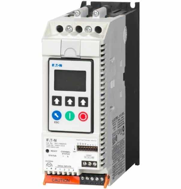
Manufactured in the UK, S811 is Eaton's answer to the demands for a reduced voltage soft starters that's very compact, multi functional, easy to install and easy to set operating parameters of. The soft starter can control the voltage to soft start and soft stop the motor. After the motor is started, internal run bypass contactors close, resulting in the motor running directly across-the-line.
The S811 is designed to be a complete package combining the silicon controlled rectifiers (SCRs), bypass contactor and overload in one, very compact unit. The S811 work with 3-phase motors up to 690 V and are available from 11 amps to 1000 amps. The S811 offers an impressive array of advanced protective features. Not only are the protective features selectable, but many offer variable settings allowing the user to fine tune the starter to meet specific system requirements.
Installation of the S811 is made simple with the keyhole mounts and the internal run bypass contactors. The internal run bypass contactors and overload protection eliminate the need for additional devices, reducing enclosure sizes, minimizing installation and wiring time and reducing overall assembly size and cost. Door or device mounted DIM enables users to safely configure, commission, monitor and troubleshoot the system at the electrical panel without opening the enclosure door, eliminating the possibility of an arc flash incident.
The S811 is also empowered by the optional accessories, including digital interface module, lug cover kits, mounting plates, vibration plates, extended ramp, power supplies, control wire connector, DIN rail power supply mounting kit, pump control, and 690V option and surge suppressors.
Key features of the S811:
- Digital Interface Module
- Bypass mode
- Pump control
- Protective features
S811+V85N3S S811 Features
1. S811+V85N3S Digital Interface Module
The digital interface module allows the user to configure the device and to read system parameters and monitor system values. The DIM includes an LCD display and keypad to scroll through the various menus. The DIM allows the user to modify control parameters, enable or disable protections, set communication variables, monitor system parameters such as line voltages and currents, and access the fault queue.
2. S811+V85N3S Communications Modules

The S811 has built-in communication capabilities through Eaton's QC (quick connect) port. The advantage of QCPort is that multiple control components can be connected to one Eaton gateway. QCPort enables the soft starter to be connected to a variety of networks, including:
- DeviceNet
- EtherNet/IP
- PROFIBUS
- Modbus
3. S811+V85N3S Bypass Mode
Internal bypass mode greatly reduces internal heating created by the greater power dissipation in the SCRs. Bypass contactor directly connects the motor to the line and improves system efficiency by reducing internal power losses.
Other S811+V85N3S S811 Features
1. General Information
- Max Current Capacity
- FLA Range
- 11 - 37
- 20 - 66
- 32 - 105
- 42 - 135
- 56 - 180
- 75 - 240
- 95 - 304
- 112 - 360
- 131 - 420
- 156 - 500
- 203 - 650
- 225 - 720
- 265 - 580
- 320 - 1000
- Bypass Mechanical Lifespan
- Insulating Voltage Ui
- Ramp Time Range
- .5 - 180 Seconds (.5 - 360 Seconds extended ramp)
2. Electrical Information
- Operating Voltage
- Operating Frequency
- Overload Setting
3. Cabling Capacity
- Number of Conductors
- Wire Sizes
- 14 - 2
- 14 - 4/0
- 4 AWG to 500 MCM
- 2/0 to 500 MCM
- Type of Connectors
4. Control Wiring (12-Pin)
- Wire Sizes in AWG
- Number of Conductors (Stranded)
- Torque Requirements in lb-in
- Solid, Stranded or Flexible Max. Size in mm^2
5. Control Power Requirements
- Voltage Range (24V ± 10%)
- Steady State Current Amps
- Inrush Current Amps
- Ripple
6. Relays (1) Class A and C
- Voltage AC - Maximum
- Voltage DC - Maximum
- Amps - Maximum
7. Environment
- Temperature
- Operating: -30 to +50°C (No derating) Consult factory for operation >50°C
- Storage: -50 to +70°C
- Altitude
- <2000m - Consult factory for operation > 2000m
- Humidity
- Operating Position
- Impulse Withstand Voltage
- Resistance to Vibration
- Resistance to Shock
8. Application Features
- Features and Benefits
- Bypass Mode
- Reduces internal heating created by the greater power dissipation in the SCRs. Bypass contactors directly connect the motor to the line and improves system efficiency by reducing internal power losses.
- Overload FLA Settings
- 31 - 100% of rated frame current and a selectable trip class (5 - 30) offers users the flexibility to fine tune the starter to match specific application requirements.
- Variable Ramp Times
- Provides unlimited starting configurations, allowing for maximum application flexibility
- Kick Start
- Enables soft starting of high friction loads
- Pump Control
- Sophisticated pump algorithms on both starting and stopping that minimize the pressure surges that cause water hammer. The pump control option will maximize the life of the pump and piping systems while minimizing the downtime caused by system failure.
- Six SCRs
- Provides smooth acceleration and deceleration performance
- Soft Acceleration/Deceleration
- Reduces wear on belts, gears, chains, clutches, shafts and bearings.
- Reduces the peak inrush current's stress on the power system.
- Minimizes peak starting torque to diminish mechanical system wear and damage.
- Control Terminal
- Removable, lockable control terminal block reduces maintenance costs. Also provides the opportunity for OEMs to reduce assembly and test costs by utilizing pre-assembled wire harnesses.
- Protective Features
- Motor Overload
- The overload meets applicable requirements for a motor overload protective device. The overload protects the motor from over heat conditions with the use of sophisticated algorithms that model true motor heating, resulting in superior motor protection and fewer nuisance trips.
- Short Circuit
- Short circuit coordination ratings with both fuses and Eaton molded case circuit breakers are available providing customers with design flexibility. The S811 has short circuit coordination ratings as an open component, an enclosed starter, and in a motor control center. The short circuit ratings can go up to 100 kA depending on application configuration.
- Jam
- Jam protection prevents the stress and damage from a jam during normal run. After the motor is started, a current greater than 300% FLA setting will cause the starter to trip on a jam fault.
- Stall
- Stall protection prevents stress and damage to a motor that has not come up to speed, or stalled after the soft start time. The S811 will trip to protect the system in the event that the motor did not get to the rated speed in the defined soft start period. A current greater than 200% FLA at the end of the soft start period will cause the starter to trip on a stall fault.
- Pole Over Temperature
- The S811 is equipped with sensors that monitor the temperature of the power poles. Over temperature protection occurs if the device's thermal capacity is exceeded. The soft starter will trip in over temperature conditions, preventing device failure.
- Phase Loss
- The S811 will detect a phase loss and trip if any phase current drops below a present value. The phase loss trip level is adjustable from 0% to 100% of the average of the other two phase levels with an adjustable trip delay of 0.1 to 60 seconds.
- Phase Imbalance
- The S811 will detect both current and voltage phase imbalances and trip if any phase becomes imbalanced as compared to the average of the other two phases. The phase current imbalance trip level is adjustable from 0% to 100% of the average of the current in the other two phases with an adjustable trip delay of 0.1 to 60 seconds.
- Reset Mode
- The S811 can be set up for automatic or manual reset on trip. The manual reset mode requires the operator to physically press the RESET button located on the soft starter. The overload can be manually reset through the UI or through the communications network.
- The automatic reset mod allows the soft starter to be automatically reset as soon as the trip condition is no longer present. With the automatic reset mod, after the fault is no longer present, the motor will be restarted as soon as the valid start signal is present.
- Phase Reversal
- The S811 will determine if the proper line phase sequence is present by default. The device will trip if the line phase sequence is something other A-B-C. The S611 can be configured to operate under reversed phase conditions (A-C-B).
- Shorted SCR Detection
- The S811 monitors the operation of the power poles and will trip under a shorted SCR condition.
- Open SCR Detection
- The S811 monitors the operation of the power poles and will trip under an open SCR condition.
- Low Current
- The S811 has low current protection that will trip if the average RMS current falls below a present value. The low current protection can be programmed as a percent of motor FLA from 0% to 100%.
- Low Voltage
- The S811 has low voltage protection that will trip if the average RMS voltage falls below a present value. The low voltage protection can be programmed as percent of nominal voltage from 1% to 99% with a trip delay of 0.1 to 60 seconds.
- High Voltage
- The S811 has high voltage protection that will trip if the average RMS voltage is greater than a present value. The high voltage protection can be programmed as percent of nominal voltage from 101% to 120% with a trip delay of 0.1 to 60 seconds.
- Monitoring Capabilities
- Monitoring
- The S811 has an impressive array of system monitoring capabilities that allow users to access real time process and diagnostic data. This data can be viewed at the device with the UI or through a communications network. Data over a communications network can provide valuable insight into the condition of the equipment and processes. Maintenance and production personnel can monitor critical operational and maintenance data from a central control station that can be located far away from the production facility. Process data can be monitored to determine system anomalies that may indicate a need for preventive maintenance or an impeding failure.
- When faults occur, real time fault data can assist maintenance in troubleshooting and planning repair resources. Remote reset signals can be given to tripped devices without the need for manual intervention by maintenance personnel.
- Average Line Current
- Provides the average of the three phase MS line currents in amps, accurate to within 2%. Current data can be used to indicate a need for maintenance. Increased currents in a fixed load application can indicated a reduction in a system efficiencies and performance, signifying system maintenance is due.
- Average Pole Current
- Provides the average of the three phase RMS pole currents in amps accurate to within 2%. The pole current is the current through the soft starter. The line and pole current will be identical in in-line applications, and will differ in inside-the-delta applications.
- Average Line Current as a % FLA
- Provides the average RMS line current as a percentage of the S811 FLA setting.
- Three-Phase Line Currents
- Provides three RMS phase line currents in amps, accurate to within 2%. Imbalances or changes in the relative phase current to one another can indicate anomalies in the motor or electrical distribution system.
- Three-Phase Pole Current
- Provides three RMS phase pole currents in amps, accurate to within 2%. The pole current is the current through the soft starter. The line and pole current will be identical in in-line applications.
- Three-Phase Line Voltages
- Provides the individual RMS three phase line voltages. Imbalances or changes in the relative phase voltage to one another can indicate anomalies in the motor or electrical distribution system. Voltages can be used to monitor electrical distribution system performance. Warnings, alarms and system actions to low or high voltage conditions can be implemented.
- Percent Thermal Memory
- Provides the real time calculated thermal memory value. The S811 calculates thermal memory value. A 100% value represents the maximum safe temperature of the motor. When the thermal memory value reaches 100$, an overload trip will occur, removing power to the motor.
- The thermal memory value can be of great use in determining an impeding overload trip condition. Alarms can be implemented in the process monitoring system warning of an impeding trip before a trip occurs, halting the process. Costly system downtime can be avoided.
- Pole Temperature
- Increase in pole temperature are caused by increase in ambient temperature, start/stop time and start duty cycles. Changes in pole temperatures represent a change in system operating conditions. Identifying unexpected operating conditions or changes can prompt maintenance and aid in process evaluation activities.
- Diagnostics
- Fault Queue
- Current fault and a fault queue containing the last nine system faults can be read through the UI or communications network. Fault identification can minimize troubleshooting time and cost and prevent arc flash incidents. The fault queue can be remotely accessed through a communications network to assist in planning maintenance resources. 30 different faults can be identified by the S811.
- Control Status
- The S811 provides data that represents system conditions that can be read through the UI or the communications network. This data identifies the status of the system and the control commands the system is requesting of the S811. This can be used for advanced troubleshooting and system integration activities.
9. Maintenance & Diagnostics
- Fault Queue
- Contains the last 9 system faults
- Monitoring
- System parameters can be accessed anywhere for increased uptime and diagnostics.
10. Standards Compliance
- IEC 60947-4-2
- EN 60947-4-2
- UL Listed (NMFT) – Frame N37 to V85
- UL Recognized (NMFT2) – Frame V10
- CE Marked
- CSA Certified (3211 06)
- CSA Elevator (2411 01)


