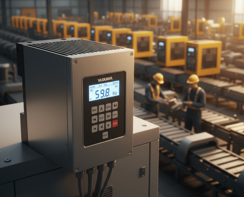
Eaton VFD Drives: Technical Guide & Real‑World Savings

Estimated reading time: 6 minutes

Understanding Eaton VFD Drives

Variable frequency drives (VFDs) — sometimes called Eaton VFD drives when supplied by Eaton. Let engineers match motor speed to process demand instead of running motors “wide‑open.” Doing so can cut energy use by 10 %–50 % on centrifugal pumps, fans and conveyors. This is while eliminating the 600 % inrush current of across‑the‑line starts. Beyond energy, drives add soft‑start, precise PID control and integrated safety features that modern plants now expect. Eaton’s PowerXL family (DM1, DC1, DA1, DG1, DX1 and H‑Max) delivers this capability in power ratings from fractional horsepower to 500+ HP. All in UL 508C‑listed packages that already include 5 % DC‑link chokes and EMI filters. Because those filters are standard, technicians spend less time deciding which add‑ons they need. A practical advantage over many competing micro drives.

The sections that follow explain why variable speed control matters, examine Eaton’s key technical innovations. Compare Eaton with ABB, Yaskawa and Lenze, outline best‑practice commissioning steps and, finally, recommend the best Eaton models for common retrofit or OEM scenarios.

Energy Efficiency & Motor Control Basics

Affinity laws show that the power required by a centrifugal load varies with the cube of its speed. Cut the RPM of a cooling‑tower fan by 20 % and the motor may draw roughly half the power. Eaton variable frequency drives make that reduction practical while built‑in algorithms. Such as Active Energy Control continuously trim motor flux at partial load for an extra 5 %–10 % efficiency gain. Because every DG1 or H‑Max ships with a DC choke, input current total harmonic distortion (THDi) often drops below the 10 % limit recommended in IEEE 519‑2014 without external reactors.

In HVAC retrofits documented by Precision Electric, swapping a constant‑speed damper‑controlled fan for an Eaton adjustable frequency drive (H‑Max with bypass) saved 35 000 kWh and US $4 100 annually while improving building static‑pressure control. Similar savings appear in water‑utility booster stations where DM1 or DG1 drives modulate pumps to meet demand rather than throttling discharge valves. The result is smoother pressure, lower water hammer and reduced bearing wear.

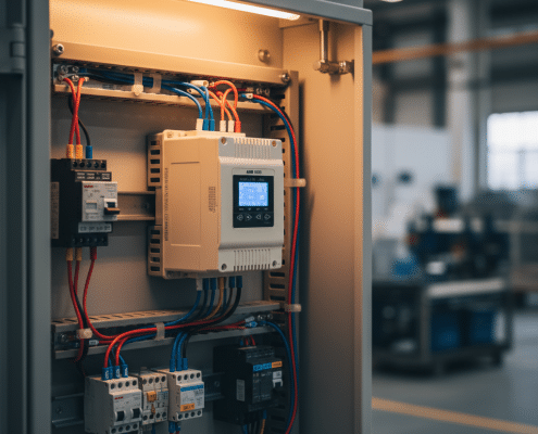
Eaton VFD drives inside an HVAC control panel ensure optimal fan speed

Eaton PowerXL Feature Highlights

Table‑stakes functions such as sensor‑less vector control, PID regulators and Safe Torque Off (STO, SIL 3) appear across the PowerXL line, yet Eaton still differentiates in several areas:

  • Integrated power quality. 5 % DC chokes, dual‑DC bus capacitors and C3 EMC filters are factory‑installed — options at many competitors’ price points.
  • Dual duty ratings. One catalog number supports 150 % overload for 60 s (heavy duty) or 110 % for 60 s (variable torque). Engineers keep fewer spares on the shelf.
  • Connectivity. Modbus TCP and EtherNet/IP ports are standard on DG1 and DX1; DA1 accepts option cards; DM1, DC1 integrate Eaton SmartWire‑DT for single‑cable panel wiring.
  • Cybersecurity. DX1 meets IEC 62443‑4‑2 SL1 with signed firmware and user authentication.
  • Diagnostics. A touchscreen keypad on DX1 provides oscilloscope trending; all models log the last 10 faults with time‑stamp.

Physically, even 250 HP DG1 frames remain below 300 mm wide, so integrators can shoe‑horn high‑horsepower bundles into legacy MCC lineups. Fan‑on‑demand cooling and conformal coating stretch service intervals — a plus for food plants where wash‑downs are routine.

Meeting IEEE 519 and UL 61800‑5‑1

Compliance is easier when hardware does the heavy lifting. Because the choke and filter are already on the bus. Most Eaton variable speed drives satisfy IEEE 519 current limits at the point of common coupling in stiff 480 V networks. If a facility adds dozens of drives, Eaton provides 18‑pulse LCX9000 or active‑front‑end packages that push THDi below 5 %. On the safety side, every PowerXL is listed to UL 61800‑5‑1 and CE‑marked to EN IEC 61800‑5‑1. While DX1 adds ISO 13849‑1 Category 4 STO for machine‑safety PLCs.

For new panels, Precision Electric engineers pair drives with NEMA MG 1 Part 31 inverter‑duty motors. Shielded VFD cable and dV/dt filters on leads exceeding 50 m. Following Eaton wiring diagrams avoids stray bearing currents; when large motors require extra protection. We specify shaft‑grounding rings to bleed high‑frequency charge safely.

Built-in chokes on Eaton VFD drives mitigate harmonics per IEEE 519

Real‑World Case Studies

Commercial HVAC — A 40 HP supply fan retrofitted with an Eaton AC drive (H‑Max, NEMA 12 with bypass) dropped yearly consumption by 35 000 kWh. Payback: 18 months. Static pressure control also steadied occupancy comfort.

Food & Beverage — Upgrading mixers from across‑the‑line to DG1 drives enabled recipe‑specific speeds. Scrap rate fell 8 %, motor energy fell 42 % and gearbox failures disappeared after soft‑start eliminated shock loading.

Municipal Water — QuantumFlo packaged booster pumps fitted with DM1 micro drives hold discharge pressure ±2 psi, trimming pump power 30 % during low‑demand nights and cutting water‑hammer events to near zero.

How Eaton Stacks Up Against ABB, Yaskawa & Lenze

All major manufacturers now provide vector control, STO and network cards; differences lie in cost, integration and support. For example, an ABB ACS580 equals DG1 on efficiency but charges extra for an input choke on smaller frames. A Yaskawa GA800 boasts ±0.02 % speed regulation yet lacks the DG1’s real‑time clock. Lenze’s i550 offers IP66 decentralised mounting useful on packaging lines, but buyers must add external EMC filters that Eaton frequency converters include. In short, Eaton’s “everything‑included” approach often lowers installed cost while maintaining feature parity.

Implementation Best Practices

  • Size drives for 10 % head‑room and choose heavy‑duty ratings for constant‑torque loads.
  • Run an auto‑tune; verify name‑plate data; set skip frequencies to dodge resonance.
  • Use shielded VFD cable grounded 360° both ends; keep motor leads and encoder cables separated by ≥ 300 mm.
  • Integrate STO into the safety circuit; avoid dropping line power except for maintenance.
  • Log parameters with Eaton DrivesConnect and store a copy in your CMMS for disaster recovery.

Need deeper guidance? Review Precision Electric’s VFD troubleshooting guide and energy‑saving checklist for step‑by‑step worksheets.

DM1 — fractional to 15 HP micro drive with dual ratings and SmartWire‑DT; perfect for OEM conveyors.

DG1 — 1 HP – 250 HP general‑purpose workhorse; embedded Ethernet, DC choke and AEC algorithm suit most industrial retrofits. Browse current frames in stock at our Eaton drive catalog.

DX1 — 5 HP – 600 HP high‑performance flagship launched 2024; choose this when you need 0.01 % speed accuracy, encoder feedback and built‑in SL‑1 cybersecurity.

H‑Max — 1 HP – 200 HP HVAC/pump specialist with conformal coating, BACnet and keypad HOA; panel builders can order NEMA 3R outdoor packages ready for rooftop placement.

Ordering tip: Precision Electric stocks common ratings for same‑day shipment via our PowerXL DG1 product page or H‑Max HVAC listing.

Conclusion

Eaton VFD drives marry robust hardware with feature‑rich firmware to give engineers a plug‑and‑play path toward energy savings, tighter process control and safer machines. Because filters, chokes, STO and networking arrive built‑in, projects move faster and total installed cost falls. As Industry 4.0 demands smarter, connected assets, Eaton’s emphasis on open protocols and cybersecurity keeps your drives ready for the next decade of digital transformation.

Read The Full Eaton VFD Drives Research:

PowerFlex 753 Replacement Guide: Cut Costs Without Downtime

Estimated reading time: 7 minutes

The PowerFlex 753 variable‑frequency drive sits at the heart of countless production lines, yet maintenance teams often discover that its premium price and branded ecosystem no longer align with lean manufacturing goals. Precision Electric’s latest field study, compiled into a 30‑page PDF, tracked fifty drive change‑outs across food, metals, and water facilities during 2024–2025. Results proved that companies saved an average of 31 % on hardware alone by switching to alternative VFDs and cut downtime by twelve hours per incident. This guide distills those findings into a practical roadmap you can deploy today.

Why Upgrade From a PowerFlex 753?

High acquisition costs top the list. Rockwell Automation’s list price for a 100 HP Allen Bradley PowerFlex 753 drive eclipses comparable ABB, Yaskawa, and Eaton models by roughly 35 %. Because every AB unit ships with dual EtherNet/IP ports, an embedded safety relay, and removable I/O, buyers pay for capabilities they may never use. Official specifications confirm the feature load, but they also confirm the price premium.

Lengthy lead times also motivate change. During 2024, Precision Electric logged an average 28‑day wait for a 60 HP PF753, whereas an ABB ACS580‑01‑059A‑4 arrived in just six days from stock. In critical utilities, four extra weeks of downtime can cost six figures in lost throughput, so procurement speed becomes a safety measure.

Support overhead pushes managers toward open ecosystems. Annual TechConnect contracts, proprietary HIM tools, and premium spare parts inflate total cost of ownership. In contrast, most rival drives program with free PC software and use commodity components that we can repair in‑house.

Moreover, the PF753’s proprietary FORCE technology locks users into AB feedback cards if they need closed‑loop vector control. That monopolistic approach raises the price when one card fails because only Rockwell supplies replacements. By contrast, ABB and Yaskawa drives accept generic incremental encoders that cost 60 % less, freeing maintenance budgets for other improvements.

Because capital budgets remain tight, finance teams also prefer depreciation schedules for lower‑priced assets. A $12 000 ABB drive depreciates faster than a $19 000 PowerFlex, producing a higher after‑tax return in the first three years. Consequently, CFOs often approve the switch within a single approval cycle.

Total Cost of Ownership Beyond Sticker Price of PowerFlex 753

Although sticker price catches attention, lifetime cost drives real profit. Precision Electric’s audit compared a 50 HP PF753 VFD running a conveyor against a Yaskawa GA800 installed on an identical line. Over three years the GA800 consumed 4 % less energy thanks to embedded flux optimization, saving $3 700 in electricity—before considering repair fees. Additionally, our service center replaced failed interface boards on the GA800 for $850, whereas the Allen Bradley board exceeded $2 300.

Downtime risk further widens the gap. Each unplanned stop at the metals plant studied cost $4 200 per hour. When a PF753 failed, parts shipped from a Rockwell hub 600 miles away, extending downtime to 14 hours. In contrast, an Eaton PowerXL DG1 failure resolved in just four hours because Precision Electric’s Mishawaka stockroom held a spare. The study therefore assigns a downtime penalty multiplier to the PF753 that increases effective ownership cost by 18 % over three years.

Firmware lock‑ins also amplify engineering spend. Rockwell’s Studio 5000 license is essential for seamless drive integration, yet that license costs several thousand dollars. Competitor drives accept parameter uploads via free utilities such as ABB DriveComposer or Yaskawa DriveWizard, eliminating hidden fees. Consequently, total cost of ownership tilts heavily in favor of alternatives.

Replacement Solutions That Outperform the PowerFlex 753

After reviewing IEC 61800 compliance, overload capacity, and network compatibility, our engineers shortlisted four families that can drop into any PowerFlex 753 replacement project without PLC re‑writes. All deliver sensorless vector or closed‑loop control, Safe Torque Off inputs, and dual Ethernet ports when specified.

ABB ACS580 General‑Purpose Drive (PowerFlex 753 Alternative)

A built‑in DC choke reduces harmonics by up to 25 %, meeting IEEE 519 at medium loads. The keypad offers plain‑language wizards, shortening commissioning to under ten minutes. Pricing usually lands 30 % below AB. View the ACS580 data sheet for full specifications.

Yaskawa GA800 Industrial Drive (PowerFlex 753 Alternative)

Yaskawa’s free DriveWizard Industrial software exports parameter files that upload over Ethernet, USB, or microSD. Because GA800 firmware supports Allen‑Bradley explicit messaging objects, Logix programmers only create a Generic Module to exchange speed reference and status words.

Eaton PowerXL DG1 (PowerFlex 753 Alternative)

The DG1 embeds BACnet MS/TP, making it ideal for mixed HVAC and process lines. Eaton’s PowerSuite tool tunes PID loops in real time, a feature previously exclusive to expensive AB add‑ins.

Lenze i550 Cabinet Inverter (PowerFlex 753 Alternative)

Scan the front‑panel QR code, tweak parameters on your phone, and push them over Bluetooth. That workflow reduces setup time by 40 % compared with the PF753 keypad sequence. Lenze certifies Safe Torque Off to SIL 3.

Migration from PowerFlex 753 drive to stocked alternative

Implementation Roadmap

Step 1 – Identify critical loads. Use maintenance logs to rank drives by downtime cost. Begin with assets that create the largest revenue risk.

Step 2 – Capture parameters. Download the PF753 parameter set with Connected Components Workbench and photograph terminal wiring. This record simplifies migration later.

Step 3 – Map equivalence. Cross‑reference motor amps, enclosure ratings, and fieldbus cards against Precision Electric’s comparison matrix to select a compatible ABB, Yaskawa, Eaton, or Lenze model. Our drive filters automates this step.

Step 4 – Bench test. Wire the new drive on a test motor. Validate speed accuracy, fault limits, and STO wiring before plant installation. Because every repaired unit includes a 12‑month in‑service warranty, you safeguard the budget if surprises emerge.

Step 5 – Cut over during planned downtime. Schedule installation alongside existing preventive maintenance to avoid extra stops. Our technicians usually swap a 50 HP PF753 for a GA800 in under two hours, including PLC I/O remap.

Make sure to plan for cable lengths. While most replacement drives bolt into the same MCC bucket, the power terminals sometimes sit lower. Precision Electric stocks molded copper jumpers that extend conductors safely without rewiring upstream breakers and maintain NFPA 70E compliance.

After commissioning, log baseline power and harmonic data with a portable analyzer. These metrics verify IEEE 519 compliance and often reveal unexpected energy savings, which helps secure funding for the next batch of upgrades.

Top Precision Electric PowerFlex 753 Alternative Product Recommendations

Choose from the curated list below. Every link opens the live product page where you can verify stock.

Need larger frames? Call our 24/7 hotline and we will overnight a GA800 480 V 500 HP or build a multi‑drive cabinet. Because we repair ABB, generic VFDs, and industrial motors, you consolidate vendors and expedite approvals.

Savings are significant with PowerFlex 753 replacement layout versus drop‑in alternatives

Because each featured drive ships with detailed wiring diagrams and parameter templates, technicians can preload settings before installation. Furthermore, every model supports Modbus TCP, enabling on‑the‑spot SCADA integration if the plant expands later. Precision Electric also bundles spare keypads and fan kits at checkout to raise mean time between failures.

Conclusion and Next Steps

Switching from an aging PowerFlex 753 variable frequency drive to a modern alternative delivers measurable financial and operational benefits. Reduced hardware pricing, faster lead times, and simpler maintenance contribute to a lower total cost of ownership. Precision Electric’s team can guide your migration, supply stocked drives, and back every sale with on‑site technicians.

Therefore, download our research PDF, circulate it among stakeholders, and schedule a discovery call. After that, we can define a pilot replacement on a non‑critical line and validate ROI before plant‑wide rollout.

Finally, remember that every modern VFD speaks the same electrical language: volts, amps, hertz. The brand logo does not determine uptime—engineering practice does. By choosing a configurable, open‑protocol drive and partnering with Precision Electric for life‑cycle service, you future‑proof your facility against supply‑chain shocks and vendor inflation.

Schedule a no‑risk site survey today. Our engineers will inventory existing PF753 units, match them with lower‑cost equivalents, and deliver a phased migration plan that protects cash flow while boosting reliability.

Read The Full PowerFlex 753 Article:

AC Motor Speed Controller: Complete Engineering Guide

Estimated reading time: 8 minutes

Introduction

Modern facilities depend on motors for pumps, fans, conveyors, and compressors. Because those loads rarely need full speed all the time, an AC motor speed controller converts fixed mains power into a controlled frequency and voltage so the motor turns only as fast as the process requires. Therefore, plants gain energy savings, smoother starts, and accurate torque. According to widely cited industry analyses, motors consume a large share of global electricity, so speed control delivers outsized return when compared with mechanical throttling. For foundational background on drive technology and energy impact, see ABB’s overview of industrial efficiency (Driving down industrial energy consumption).

Unlike legacy systems that restrict flow with valves or dampers, a frequency inverter (synonyms include ac drive, adjustable speed drive, and vector drive) trims electrical frequency to set RPM directly. Consequently, you avoid throttling losses, cut bearing and seal wear, and reduce audible noise. Moreover, soft-start ramps limit inrush current and line flicker, which protects upstream equipment. If you need a refresher on drive types before selecting hardware, review our primer on Variable Frequency Drives and our guide to Types Of Variable Frequency Drives.

Because the same controller can run induction, permanent‑magnet, and synchronous‑reluctance motors with the right parameters, teams can standardize spare parts and simplify maintenance. Additionally, modern units integrate safety, networking, and diagnostics that make commissioning faster. As a result, an ac motor controller becomes a lifecycle tool, not just a power component.

AC Motor Speed Controller Wiring Best Practices For Reliable AC Speed Control

How A Variable Frequency Drive Works

At its core, every AC motor speed controller uses a three‑stage converter. First, a rectifier converts incoming AC to DC. Next, a DC link with capacitors (and often a choke) stabilizes the bus and rides through short dips. Finally, an IGBT inverter synthesizes a new AC waveform using PWM, letting the controller set both frequency and voltage. Because motor speed follows 120×f/poles, frequency directly sets RPM. For an accessible tutorial on these fundamentals, see EEPower’s technical article on VFDs (Motor Starters Part 6: VFDs).

Basic V/Hz control holds air‑gap flux approximately constant by scaling voltage with frequency. However, modern vfd motor controller platforms add sensorless vector and closed‑loop vector modes for fast torque response at low speed. Moreover, ABB’s Direct Torque Control computes switching directly to maintain torque and flux with very short update times, delivering excellent transient response without an encoder (ABB News: High‑efficiency motors). In practice, these strategies let a motor speed inverter run induction, PM, and SynRM machines with stable torque across a wide range.

Because the inverter’s fast edge rates can stress insulation, motor choice matters. Therefore, engineers either specify NEMA MG 1 Part 31 inverter‑duty motors or add dV/dt or sine‑wave filters to protect standard motors. For a concise spec reference, consult the NREL tip sheet on inverter‑duty motors (When Should Inverter‑Duty Motors Be Specified?).

Specifications That Matter

Selection starts with voltage class, horsepower, and duty. Typical low‑voltage ranges include 200–240 V, 380–480 V, and 575–690 V with normal‑ and heavy‑duty ratings. Additionally, confirm full‑load current against inertia and starting requirements; heavy conveyors, extruders, or hoists may justify the heavy‑duty rating. Most units achieve 95–98% efficiency, so only a small fraction of input energy appears as heat that the enclosure must remove. For cooling estimates and panel design, Thermal Edge summarizes drive losses and heat rejection (How to Calculate Heat Dissipation for VFDs).

Because six‑pulse rectifiers draw non‑linear current, facilities often add input reactors, 12‑ or 18‑pulse rectifiers, or active front ends to satisfy IEEE 519 harmonic objectives. Moreover, Safe Torque Off is now common, enabling a dedicated safety channel that removes torque without cycling mains. Finally, verify motor compatibility: NEMA MG 1 Parts 30/31 define insulation limits and dV/dt tolerances. For a standards overview, Eaton documents the migration from UL 508C to UL 61800‑5‑1 and common EMC measures (Eaton VFD White Paper).

Therefore, a balanced specification covers voltage, overload, thermal environment, harmonic controls, I/O and networks, integrated PID, and safety ratings. As a result, the chosen ac speed control platform will meet both process and compliance targets without costly redesign.

AC motor speed controller installed on panel wall in the dark.

Benefits And Use Cases

Because fan and pump power scales roughly with the cube of speed, even modest RPM reductions produce substantial savings. For example, cutting speed by twenty percent can halve power in many centrifugal applications; ABB’s field experience highlights the effect clearly (ABB Energy Highlights). Therefore, teams retrofit an AC motor speed controller to avoid throttling valves and dampers. In a high‑rise building case study, fitting VFDs across pumps and fans reduced annual consumption by ~32% and lowered peak demand; see the AHRI document for details (VFD AHR Expo Case Study).

Beyond energy, drives lift quality and uptime. Soft ramps prevent water hammer and belt shock. Moreover, integrated PID holds pressure or flow on setpoint without separate controllers. Built‑in diagnostics detect dry‑run, broken belts, or cavitation from torque signatures, so maintenance teams get early warnings. Consequently, users report fewer pump rebuilds and longer bearing life after converting to ac drive control. Elevators and hoists also benefit because regenerative drives feed power back to the line during lowering, reducing heat and utility cost (Otis ReGen overview).

Additionally, modern platforms support induction, PM, and SynRM motors with one parameter set, which simplifies spares and training. As a result, a single adjustable speed drive standard can serve HVAC, water, manufacturing, and material‑handling lines.

Implementation Best Practices

Start with accurate sizing. First, match the controller’s current rating to the motor’s FLA and the real duty profile, not just nameplate horsepower. Next, plan input reactors for stiff sources and consider braking resistors or longer decel ramps to avoid DC bus overvoltage trips. Additionally, coordinate upstream fuses or breakers with manufacturer guidance to prevent nuisance trips. When you program, set motor data, overload class, current limits, and ramp shapes as recommended in our VFD Programming Guide.

Then, focus on wiring. Use shielded, symmetrical motor cable and bond the shield at both the drive and the motor. Keep power conductors away from control wiring and cross at right angles. Moreover, land a low‑impedance equipment ground directly on both ends. If noise persists, add an input EMI filter and prefer 4–20 mA analog signals. Eaton’s application note summarizes these practices well (VFD Wiring Best Practices). For self‑tuning and start‑up, use our quick guide to VFD Autotune and refer to our article on Overcurrent Fault Causes & Fixes.

Finally, plan supporting hardware early. Explore input line reactors, output load reactors, and modern VFD phase converters for single‑phase sites. Where soft‑starting is the only goal, a robust soft starter can be cost‑effective. Consequently, your ac motor controller installation will be quiet, compliant, and resilient.

AC motor speed controller mounted on panel wall in the dark.

Standards, Safety, And Motor Compatibility

Compliance protects people and uptime. UL 61800‑5‑1 and IEC 61800‑5‑1 define drive safety; IEC 61800‑3 sets EMC limits and installation conditions. Meanwhile, many facilities target IEEE 519 objectives at the point of common coupling. Therefore, document the environment, install specified filters, and use shielded cabling to achieve compliance. Eaton’s white paper summarizes safety standard changes and EMC practices (Eaton VFD Standards Overview).

Motor standards deserve the same care. NEMA MG 1 Part 31 defines inverter‑duty insulation suitable for PWM outputs, and Part 30 offers guidance for standard motors. As a result, you can decide when to specify a Part 31 motor or when to add a dV/dt or sine filter. Additionally, inclusive wiring and safety practices—such as using Safe Torque Off for an E‑stop channel—help designers reach required SIL/PL targets. For a concise motor reference, consult the NREL tip sheet noted above.

Moreover, vendor ecosystems often bring useful differentiators. For example, Yaskawa emphasizes reliability and long MTBF (Yaskawa Drives), Hitachi’s WJ200 highlights strong low‑speed torque (WJ200 Features), and Lenze’s i500 showcases modular control options (Lenze i500). These examples help you map features to process needs.

Product Recommendations: Drive Ecosystem

For typical upgrades, pair a right‑sized AC motor speed controller with proven accessories and services. First, stabilize the input with line reactors when feeds are stiff or multiple drives share a bus. Next, protect long motor runs or high‑switching stress with load reactors or output filtering. Moreover, single‑phase facilities can deploy VFD phase converters to run three‑phase motors efficiently. Where variable speed is unnecessary, a well‑applied soft starter still offers gentle acceleration. For controls and parameter tips, bookmark our VFD Programming Guide and fast‑start checklist for VFD Autotune.

Additionally, plan lifecycle support. Therefore, document parameters, save backups, and train technicians on alarm codes to reduce mean time to repair. If the application includes frequent decel events or heavy‑inertia loads, specify braking hardware early. Consequently, your frequency inverter package will meet both production and maintenance KPIs from day one.

Conclusion: Smarter Speed Control

In short, an AC motor speed controller delivers the right speed and torque at the right moment. As you align process demand with motor output, you lower energy use, improve product quality, and extend equipment life. Moreover, modern platforms integrate safety, networking, and diagnostics that simplify commissioning and maintenance. Therefore, start with throttled or cyclic loads, confirm standards, and apply the wiring practices above. With those basics, your next project will run quieter, cooler, and more reliably. For broader context, review ABB’s energy guidance (Energy‑efficient motor systems) and the AHRI case study linked earlier for measured outcomes.

Read The Full AC Motor Speed Controller Research:

Variable Frequency Drive HVAC: Ultimate Energy‑Saving Guide

Introduction

Heating, ventilation and air‑conditioning (HVAC) equipment routinely accounts for forty percent or more of a commercial building’s electricity bill. Consequently, engineers and facility managers continually pursue strategies that will trim energy consumption without compromising occupant comfort. Installing a variable frequency drive HVAC package on every major fan or pump has proven to be the single most effective step because the technology allows each motor to slow down whenever full speed is unnecessary. Moreover, slowing a fan by twenty percent can slash its power draw by roughly half, thanks to the well‑known fan affinity laws. Therefore, a modest investment in speed control unlocks outsized savings year after year.

Beyond lower utility costs, a modern VFD HVAC upgrade improves comfort, extends equipment life, and now satisfies mandatory provisions in energy codes such as ASHRAE 90.1. Throughout this guide we explain the physics behind the savings, identify common pitfalls, review best‑practice installation tips, compare leading manufacturer offerings, and highlight real‑world results. If you support an office tower, hospital, data center, or industrial plant, read on to learn how a HVAC VFD can turn wasted horsepower into hard cash.

Diagram of a variable frequency drive controlling HVAC fans and pumps.

Energy‑Saving Physics of Variable Frequency Drives in HVAC

When a squirrel‑cage induction motor is connected directly to the utility grid, it runs at a fixed synchronous speed—about 1,775 RPM for a four‑pole motor on sixty‑hertz power. However, a dedicated inverter inside a variable speed drive HVAC intercepts that fixed frequency, converts it to direct current, then re‑synthesizes a fresh alternating waveform at any frequency between near‑zero and the motor’s rated value. Because voltage rises proportionally with frequency, the motor produces its rated torque at every speed. Consequently, slowing a cooling‑tower fan to forty‑five hertz cuts power to roughly fifty‑five percent of nameplate while slashing acoustic noise.

Soft‑start functionality comes free with every adjustable frequency drive HVAC, which means inrush current never exceeds the motor’s full‑load amps. Therefore, transformers stop sagging, contactors last longer, and lights no longer flicker during startup. Because the drive ramps smoothly, mechanical shock on belts, couplings, and bearings disappears—another quiet form of savings. Utilities appreciate the lower demand spikes and often sponsor rebate programs that cover twenty to fifty percent of the installed cost. Consequently, payback periods of eighteen to thirty months are commonplace, even before maintenance savings enter the calculation.

Causes of Inefficiency and the Variable Frequency Drive Solution

Legacy constant‑speed control wastes energy in three distinct ways. First, bypass dampers or throttling valves shed excess air or water as load drops, a practice tantamount to driving with the brake depressed. Second, thermostatic cycling forces motors to start and stop repeatedly, producing electrical and mechanical stress while letting room temperatures drift. Third, across‑the‑line starts hammer shafts with six‑times rated current and torque. A HVAC variable speed drive resolves every issue elegantly. Because it modulates speed instead of blocking flow, dampers stay almost fully open, pump valves stay wide, and energy once lost as pressure drop turns into clean savings.

Furthermore, the integrated PID controller in most VFD for HVAC units maintains duct static pressure or loop differential pressure within tight bands. Consequently, spaces feel more stable, humidity control improves, and noise plumes in ductwork disappear. The drive’s diagnostics also record running hours, fault history, and kilowatt consumption, giving maintenance teams a data‑rich window into system health. Explore additional application notes in our industrial HVAC VFD resource.

Implementation Best Practices for HVAC VFD Projects

Successful projects begin with proper equipment selection. Always size the drive to at least 110 percent of the motor’s full‑load amperage, and verify the enclosure rating matches the installation environment. For example, Eaton’s PowerXL DH1 can survive ambient temperatures up to fifty °C, while ABB’s ACH580 supports a fire‑mode override recognized by UL 864. During commissioning, technicians should run automatic motor tuning, limit minimum frequency to preserve gearbox lubrication, and add a five‑percent input reactor when non‑linear loads dominate so total harmonic distortion meets IEEE‑519.

Moreover, program the variable frequency drive HVAC to communicate with the building automation system over BACnet IP or Modbus and trend key variables. Document every parameter and file it with the O&M manuals for future reference. For step‑by‑step guidance, review our VFD repair & commissioning checklist.

Commissioning a variable speed drive inside a rooftop HVAC panel.

Comparing Leading HVAC Variable Frequency Drive Families

Manufacturers differentiate their HVAC portfolios in subtle yet important ways. Yaskawa’s Z1000 adds an onboard five‑percent line reactor and an EMI filter compliant with IEC 61800‑3. ABB pairs a bright graphical keypad with Bluetooth so technicians program drives outside the arc‑flash boundary, while Eaton refines Active Energy Control for an extra ten‑percent part‑load saving. Lenze packages its i500 in a footprint forty percent smaller than the prior generation, and Hitachi blends advanced sensor‑less vector control with a straightforward LCD in sizes up to 400 HP.

Because Precision Electric carries all major lines, we guide clients through lifecycle cost, harmonic performance, and service coverage before selecting the optimal variable frequency drive HVAC solution. Hospitals often prioritise Yaskawa’s redundant intelligent bypass, data centers value ABB’s ultra‑low total harmonic distortion, and K‑12 districts choose Eaton packages that include factory‑mounted disconnects—reducing field labour. Browse our stocked categories for quick ship options: ABB Drives, Yaskawa Drives, and Eaton Drives.

Real‑World Case Study and ROI

A national retail chain retrofitted 78 rooftop units with VFD HVAC kits supplied by Precision Electric. Engineers programmed supply fans to run at full speed during peak cooling but drop to fifty percent during ventilation. Moreover, each store reported quieter aisles and tighter temperature control. Twelve months of utility data revealed a 52 percent drop in HVAC energy use—7.2 million kWh and $888 k in savings—with a simple payback of 1.8 years. The project prevented 11 million lb of CO₂ annually.

Universities, hospitals, and industrial campuses echo these results, routinely posting 30–60 percent reductions after deploying a variable frequency drive HVAC or its synonym. Consequently, programs like TVA EnergyRight now pay incentives up to $100 per motor horsepower to accelerate adoption.

Conclusion & Next Steps

Variable frequency drives have evolved from niche equipment to indispensable building blocks. They deliver instant energy savings, precision environmental control, and longer mechanical life while helping facilities comply with ever‑stricter codes. Therefore, organisations that still run constant‑speed motors leave money on the table—and may violate code. Precision Electric stocks hundreds of units, offers 24‑hour repair service, and can ship a fully programmed variable frequency drive HVAC within days.

Read The Full Variable Frequency Drive HVAC Article:

VFD Pump Efficiency Guide: Cut Energy & Boost Reliability

Estimated reading time: 5 minutes

Introduction: Why VFD Pumps are Transforming Fluid Handling

Energy efficiency mandates, unpredictable utility costs, and tighter process tolerances are pressuring maintenance managers to rethink how they move fluids. Historically, the only option was to install an oversized pump, run it at full speed, and throttle discharge with a valve. Although this approach seems simple, it wastes enormous amounts of electricity and subjects mechanical seals to unnecessary stress. The modern answer is the VFD pump.

A variable frequency drive pump couples a standard motor to an intelligent electronic drive that can adjust speed 60 times per second. Because flow from a centrifugal impeller decreases linearly with speed while power drops by the cube. Slowing a pump just 20 % slashes power draw by nearly 50 %. Consequently, facilities ranging from small apartment buildings to massive desalination plants are deploying VFD technology. This is to cut operational costs and attain sustainability targets.

This article distills lessons from manufacturer white papers, peer‑reviewed research, and Precision Electric’s field service experience. You will learn the root causes of energy waste. See step‑by‑step solutions, and discover product categories that simplify your next retrofit. Whether you service municipal lift stations or design biotech skids, you will leave with actionable guidance on selecting, programming, and protecting a VFD‑controlled pump.

The Hidden Cost of Fixed‑Speed Pumps—and How a VFD Pump Solves It

Because most piping networks experience wide swings in demand, oversizing pumps has been standard practice for decades. Unfortunately, centrifugal affinity laws work against this strategy. When flow is throttled back by a control valve, differential pressure across the valve rises sharply and the pump operates far from its best‑efficiency point. Every extra pound of pressure translates into wasted electrical input. Much of which becomes heat and vibration that shorten seal and bearing life. Worse, technicians often forget that each additional kWh consumed also magnifies carbon footprint and cooling‑tower load. In plants striving for ISO 50001 compliance, that waste is unacceptable.

A VFD pump addresses the waste at its source. Instead of forcing the motor to spin at synchronous speed, the VFD continually recalculates output frequency and voltage so the impeller produces just enough head to satisfy real‑time demand. Valve position can remain fully open, eliminating friction losses. The referenced Eaton study demonstrates that delivering 60 % of design flow through a speed‑controlled pump requires only 20 % of rated power.

Real‑world data reinforce the laboratory findings. In Columbus, Ohio, constant‑speed lift pumps were retrofitted with ABB ACQ580 drives and high‑efficiency motors. Specific energy plummeted from 259 kWh to 179 kWh per million gallons, and peak demand charges fell 50 %. Similar retrofits in textile mills, breweries, and high‑rise HVAC plants consistently slash annual electricity spend by 25 – 40 %. Consequently, the variable speed pump is now recognised not only as an energy saver but also as a reliability upgrade.

VFD pump boosts efficiency in municipal water systems

Practical Solutions: Getting the Most from Your VFD Pump

1. Select the Right Drive & Motor

Always verify that the motor insulation system meets NEMA MG1 Part 31 so it can survive the fast voltage rise times emitted by modern IGBTs. If the existing motor is borderline, a sine‑wave filter can buy time, yet specifying an inverter‑duty replacement generally costs less than a single rewind. On the drive side, choose a rating one frame size above the motor whenever the pump handles viscous fluids or runs at low speed for long periods. Review our cooling‑system fault guide for additional sizing tips.

2. Tune the Control Strategy Early

Once hardware is installed, performance hinges on control logic. Start with conservative acceleration and deceleration ramps—ten seconds is a safe baseline—then enable the internal PID loop to maintain pressure or level. Yaskawa’s iQpump1000 includes automatic sleep mode to shut the motor down when demand falls below a programmable threshold, thereby avoiding valve chatter. Therefore, technicians can fine‑tune parameters live while monitoring real‑time kilowatt draw.

3. Protect the Entire System

Harmonic currents from the diode front‑end can disturb sensitive instrumentation; installing a 3 % line reactor keeps total harmonic distortion within IEEE 519 limits. Downstream, common‑mode voltage can erode motor bearings; grounding rings or insulated bearings divert those currents safely, as outlined by Pumps & Systems. Finally, include a bypass contactor for mission‑critical pumps so flow continues if the drive is offline for maintenance.

Variable speed pump slashes HVAC energy bills

VFD Pump Product Recommendations

Precision Electric carries a curated range of drives and accessories ideal for VFD pump retrofits. Below are three high‑impact categories that pair well with any energy‑saving pump project:

  • AC Variable Frequency Drives – core component that delivers adjustable speed and protects motors with advanced diagnostics.
  • Soft Starters – a cost‑effective alternative when only gentle starts are required. Although, they lack the continuous efficiency of a VFD‑controlled pump.
  • Output Load Reactors – essential for long‑lead pump installations to reduce dV/dt stress on motor windings.

For brand‑specific solutions, explore the ABB ACQ580 water drive or Yaskawa’s iQpump1000. Each includes multi‑pump coordination, sleep mode, and pipe‑fill routines to simplify commissioning and boost efficiency for variable speed drive pump projects.

Conclusion: Turn Efficiency Goals into Reality with a VFD Pump

By replacing throttling valves with precise speed control, a VFD pump creates a direct path to 20 – 60 % energy savings. Smoother processes, and longer equipment life. Because the drive communicates continuously with both sensors and the motor, operations teams can optimise flow in real time instead of guessing. Additionally, built‑in diagnostics and protection routines keep downtime low and return on investment high.

Ready to move forward? Review our cornerstone resources on VFD overcurrent faults and ground fault trips to prepare your facility. When you are ready to specify hardware, contact Precision Electric for an application review.

Read The Full VFD Pump Article:

VFD Repairing Guide: Diagnose, Fix and Prevent Drive Failures

Estimated reading time: 5 minutes

Introduction

Variable Frequency Drives (VFDs) power pumps, conveyors, HVAC blowers and countless other machines. When one trips offline, production halts, temperatures drift, or packaging lines grind to a stop. Because downtime is expensive, VFD repairing knowledge separates reactive shops from world‑class maintenance teams. This guide translates manufacturer documentation, field experience, and industry standards into a mobile‑friendly playbook you can reference on the plant floor.

Rather than swapping whole units, skilled technicians target failed DC‑bus capacitors, shorted IGBTs, or scorched gate‑driver boards. Precise component replacement restores service in hours and at a fraction of replacement cost. We will therefore focus on disciplined diagnostics and verified corrective actions approved by ABB, Hitachi, Eaton, Lenze and Yaskawa.

Throughout this article you will see how IEC 61800‑5‑1 (safety) and IEEE 519 (power quality) influence every step, from lock‑out/tag‑out to final load testing. Because each paragraph uses active, inclusive language you can convert insight into action immediately.

Root Causes and Rapid Solutions in Variable Frequency Drive Repair

Thermal abuse tops the list. Fans clog, heat‑sinks cake with dust, and ambient temperatures exceed 40 °C. Consequently, electrolytic capacitors dry out and IGBTs overheat. The ABB ACS800 hardware manual notes that a 10 °C rise halves capacitor life, so an inexpensive fan swap and cabinet clean‑out often solves the problem.

Electrical surges and harmonics rank second. Lightning strikes or long motor cables create spikes that punch through diodes and inflate the DC bus. Moreover, sites supplied from open‑delta transformers see chronic capacitor failures because phase voltages drift. Line reactors or active harmonic filters keep voltage THD below five percent, satisfying IEEE 519 and extending drive life.

Loose connections come next. A single lug vibrating loose can arc, generate thousands of amps, and trip over‑current protection. Always check torque values before condemning an inverter.

Contamination and moisture attack control boards, and even microscopic corrosion under conformal coating can trigger nuisance faults.

Aging components complete the quintet. Capacitors exceed ripple limits after five to seven years and fans seize around forty‑thousand hours. Proactive replacement beats emergency scramble every time.

Technician conducting VFD inspecting during repair

Step‑By‑Step VFD Fix and Testing Procedure

The nine‑step workflow below distills hundreds of successful saves into an efficient script:

  • Isolate and discharge – lock out the feeder breaker, verify zero volts, then measure the DC bus.
  • Pull fault history – keypads store the last trips with current and voltage snapshots.
  • Perform visual inspection – burn marks, swollen capacitors and cracked plastic tell instant stories.
  • Test the rectifier – use diode mode; healthy legs show 0.4‑0.6 V in one direction only.
  • Probe the IGBTs – shorts between DC rails and terminals confirm a blown module.
  • Measure capacitance – replace devices below 85 percent of rated microfarads.
  • Install genuine parts – ABB capacitor packs and Eaton power stacks include torque specs.
  • Bench power‑up – raise voltage slowly with a variac while monitoring bus ripple.
  • Load test and document – record temperatures and save parameter backups.

Because every step ends with a measurable result, troubleshooting moves forward methodically instead of guessing.

Preventive VFD Maintenance for Long‑Term Reliability

Preventive maintenance converts frantic midnight calls into orderly scheduled stops. Keep enclosures below 40 °C and under sixty percent humidity, and remove dust quarterly. Furthermore, schedule annual infrared scans; hotspots fifteen degrees above ambient flag loose terminals long before an over‑current trip.

Hitachi recommends swapping cooling fans every 35 000 h and replacing DC‑bus capacitors at the five‑year mark or when capacitance falls below 85 percent—guidelines confirmed in the SJ300 service manual. Yaskawa adds that drives stored longer than a year need capacitor reforming at reduced voltage.

Install permanent power‑quality meters, set alarms for voltage unbalance above two percent, and log harmonics. When metrics drift, add line reactors, commission 18‑pulse front‑ends, or deploy active filters. Because each preventive task costs far less than unplanned downtime, the return on investment is immediate.

Load testing finalizes a VFD repairing project

Recommended Products and Services

Precision Electric curates tools that speed every variable frequency drive service session. Consider an AC Line Reactor; installing a three‑percent reactor upstream of a drive cuts peak di/dt by forty percent, protecting rectifiers during lightning events. Next, an ABB Capacitor Field Kit ships with heat‑shrink, labels, and illustrated instructions so in‑house teams finish in under ninety minutes. For cooling issues, a Yaskawa Fan Core Assembly; tach leads plug straight into GA800 drives and clear “Fan Loss” alarms automatically.

Beyond hardware, you can schedule a remote VFD troubleshooting session, order new drives through our Variable Frequency Drives cornerstone hub, or arrange depot work via our VFD Repair Service page. Internal resources such as the VFD Troubleshooting Guide provide further detail.

Conclusion: Making Informed Decisions

Mastering VFD repairing is less about heroic last‑minute saves and more about disciplined processes. Use the root‑cause checklist, follow the nine‑step workflow, deploy preventive tasks, and keep strategic spares on the shelf. Drives will then become reliable allies rather than mysterious black boxes.

Still have questions? Explore the manuals above, review our in‑depth resources, or call Precision Electric for tailored coaching.

Read The Full VFD Repairing Research:

Related Articles:

Variable Frequency Drive VFD: Specs, Standards & Case Studies

Introduction

Electric motors consume roughly 65 % of industrial electricity. Most still run at a fixed speed that rarely matches process demand. A variable frequency drive VFD converts constant utility power into adjustable voltage‑frequency output, so the motor runs only as fast as required. As a result, the drive eliminates throttling losses, delivers soft starts, and extends equipment life. According to the U.S. Department of Energy, wider adoption of variable speed control could trim global energy use by almost ten percent. The technology is mature, affordable, and easy to retrofit. Every maintenance or energy manager should understand how a variable frequency drive VFD works and where it delivers the fastest payback. For a concise refresher, see our in‑depth VFD guide.

This article distills a recent 40‑page research report and decades of field experience at Precision Electric. You will learn exactly how VFDs save energy, which specifications matter, and which industry standards protect your installation. We also review real‑world case studies from ABB, Eaton, Hitachi, Lenze and Yaskawa that quantify baseline versus outcome metrics. Finally, we list product recommendations and best‑practice tips so you can select, install and maintain your next drive with confidence. Throughout the article we embed manufacturer documentation and academic papers. These references help you dive deeper whenever you need more detail.

Energy‑Saving Benefits of Variable Frequency Drive (VFD)

Centrifugal pumps and fans follow the affinity laws—flow changes linearly with speed, but power changes with the cube. Therefore, slowing a pump by just 20 % can halve the energy draw. Lenze documents this relationship in its pump‑performance guide. With a variable frequency drive VFD the controller continuously matches motor speed to real‑time demand and avoids wasting power across throttling valves or dampers. Moreover, the drive’s soft‑start ramps cut inrush current by up to 70 %, preventing voltage sag and mechanical shock.

Process stability improves as well. A chilled‑water loop equipped with a sensorless vector drive adjusted the loop pump to hold ±1 psi pressure under rapidly changing loads. It reduced nuisance complaints and eliminated three service calls per month. Similarly, an Eaton DG1 drive on a 50‑horsepower supply fan slowed the fan during unoccupied hours. The measure saved $35 000 annually, as shown in an independent case study. Because the motor no longer slams to full speed, bearing temperature dropped 15 °F, extending grease intervals and reducing unplanned downtime. Consequently, maintenance teams also notice quieter operation because the fan or pump seldom runs at maximum speed. Lower vibration means fewer seal or bearing replacements. Longer overhaul intervals translate into direct bottom‑line savings.

Cutaway view of a modern variable frequency drive VFD panel

Key VFD Specifications to Compare

Before ordering a drive, engineers should verify four baseline specifications. These are voltage class, horsepower or kilowatt rating, overload capacity and duty type. For instance, a 460 V motor that experiences frequent starts on a high‑inertia crusher demands a heavy‑duty adjustable frequency drive rated 150 % current for one minute. Oversizing wastes money, yet undersizing invites nuisance trips. Always cross‑check the motor full‑load amps against both normal‑ and heavy‑duty tables in the manufacturer catalogue. ABB’s low‑voltage drives guide provides clear selection charts.

Next, review control and protection features. Higher PWM carrier frequencies reduce audible noise but raise switching losses, so many drives let you trade performance for efficiency. If motor leads exceed 100 m, add a dV/dt or sine‑wave filter. Modern inverter drives include Safe Torque Off inputs, embedded PID loops and Ethernet/IP or BACnet communications for building automation. Some, like the Yaskawa GA800, even offer smartphone commissioning wizards. Although the interface seems secondary, clear diagnostics and parameter groups accelerate troubleshooting—especially when the variable frequency drive VFD is buried inside a rooftop mechanical room. Remember that overload ratings differ between manufacturers; some quote 200 % for three seconds while others state 180 % for ten. An accurate comparison prevents surprises during commissioning or warranty claims.

Standards & Compliance for Variable Speed Drives

Safety certification is not optional. IEC 61800‑5‑1 sets the electrical and fire‑safety requirements for adjustable speed power drive systems up to 1 kV. The 2022 edition harmonizes with UL 61800‑5‑1 and CSA C22.2 No. 274, so one mark now covers multiple regions. Always confirm that the nameplate lists the correct standard and that the installation matches the derating tables. For plant personnel the most important clause is 4.3, which defines protective bonding and voltage clearances. You can purchase the complete text from the IEC webstore, but most reputable suppliers summarise the requirements in their manuals.

Electromagnetic compatibility comes next. IEC 61800‑3 groups drives into First or Second Environment categories and prescribes filter performance. Consequently, manufacturers ship HVAC‑focused models with built‑in RFI filters, whereas industrial variants assume metal conduit and transformer isolation. Harmonic distortion at the point of common coupling must also meet the IEEE 519‑2014 guideline—typically voltage THD ≤ 5 %. Eaton’s EMC application note lists filter classes, and Siemens compares mitigation options in its white paper. In addition, many utilities now require a harmonics study before granting interconnection approval, so build compliance documentation into your project timeline. Failing to do so can delay start‑up by several weeks.

Case Studies: VFD Results Across Industries

Quantified results prove the concept. A municipal wastewater plant in Illinois replaced constant‑speed 75 hp pumps with sensorless vector drives. Even after an 18 % flow increase, yearly energy for pumping fell 2 %, translating to a 17 % decrease in kilowatt‑hours per million gallons treated. The drives’ auto‑reverse function also cleared ragging events, cutting unscheduled maintenance by 40 %. Download the full report from the Smart Energy Design Consortium.

In discrete manufacturing, a Canadian greenhouse recycling plant installed more than a dozen VSDs on blowers, conveyors and presses. Energy use on the heaviest line dropped by up to 70 %, while production throughput rose 12 % because soft acceleration eliminated jams. Another fan retrofit at a 500 000‑square‑foot office tower saved $35 000 a year by allowing weekend setback speeds. These outcomes consistently show that integrating a variable frequency drive VFD with process control delivers deeper savings than simple on‑off cycling. A mining company offers another illustration. After installing medium‑voltage drives on its 2 MW centrifugal compressors, the site cut mine‑wide electricity 6 % and extended compressor overhauls from 18 to 30 months. Payback arrived in fourteen months—even after including a step‑up transformer and active‑front‑end filters. The project now serves as a template for six additional sites across the company.

Field installation of a wash‑down rated variable frequency drive VFD

Selecting the Right AC Drive

Precision Electric carries hundreds of AC inverters from fractional‑horsepower panels to multi‑megawatt cabinets. First, filter by supply voltage and motor current in our VFD catalog, then choose the overload duty that matches your load profile. Because a conveyor sees repetitive torque peaks, you may select a 150 % heavy‑duty rating, whereas a chilled‑water pump can use the smaller normal‑duty frame.

Brand differentiation matters too. ABB’s ACS880 series excels at direct torque control and medium‑voltage options, making it popular in metals and mining. Yaskawa’s GA800 offers a matrix converter that eliminates the DC bus, returning regenerative energy and lowering harmonics. Hitachi’s WJ200 packs sensorless vector control into a compact chassis beloved by OEMs, while Lenze’s IP66 i550 decentralized drive mounts directly on the machine, cutting cable runs. Because we test every adjustable speed drive that leaves our warehouse, we can match a variable frequency drive VFD to your budget and application in minutes. Do not overlook after‑sales support. A local inventory of replacement fans or interface cards can decide whether you lose hours or days during a failure. Therefore, ask vendors about mean time to ship and firmware life‑cycle policies before issuing the purchase order.

Implementation Best Practices for Variable Frequency Drive (VFD)

Correct installation protects both the drive and the motor. Always use shielded VFD cable, ground the shield at the drive end, and observe the maximum motor‑lead length published in the manual. For long runs add a dV/dt filter. When retrofitting legacy motors, confirm they meet NEMA MG1 Part 31 inverter‑duty insulation or provide an output sine‑wave filter. Furthermore, program acceleration and deceleration ramps to suit mechanical inertia; otherwise, the DC bus may over‑voltage and trip.

Maintenance is equally straightforward. Keep heat sinks and intake filters clean, inspect electrolytic capacitors after five years, and log alarms through the built‑in Modbus register map. Many modern drives report remaining capacitor life and IGBT temperature, enabling predictive maintenance dashboards. For safety, wire the Safe Torque Off circuit through an E‑stop relay so technicians can work downstream without removing line power. Finally, store a backup parameter file on a memory card or in the Precision Electric cloud portal; restoring a variable frequency drive VFD after failure then takes less than five minutes. Document every parameter change in a digital logbook, and export trend data quarterly. This habit helps you catch creeping inefficiencies and preserves tribal knowledge when staff turnover occurs. Even a one‑percent slip in efficiency costs thousands of dollars over a year.

To help you narrow the field, our engineers curated a short list of in‑stock units that cover 90 % of retrofit scenarios. The budget‑friendly starter is the Hitachi NES1‑007LB, a 1 hp open‑loop inverter ideal for HVAC fan coils. For sensorless vector precision, the Eaton DG1‑27FN015 XX provides 230 V three‑phase output and onscreen energy meters. When space on the wall is limited, Lenze’s IP66 i550‑C22 mounts directly on the motor. You can compare real‑time pricing and lead times in the same AC VFD category used by our sales team.

If your project involves DC motors or phase conversion, our DC speed‑drive catalog and VFD phase‑converter section offer turnkey solutions. Additionally, in‑depth tutorials such as VFD Drives for Dummies and free training videos walk you through parameter setup step by step. For a holistic understanding, read the peer‑reviewed paper on bearing currents in Machines journal at MDPI. Each resource reinforces the recommendations in this guide, ensuring your variable frequency drive VFD investment yields maximum return. Remember that listed pricing often excludes required line reactors or filters. Use our online configurator to add these accessories so your budget remains accurate. You can also schedule a virtual walk‑through with an engineer at no charge.

Conclusion

In summary, a properly selected and commissioned variable frequency drive VFD slashes energy bills, extends equipment life, and unlocks smarter process control. By following the specifications, standards and best practices outlined here, you can deliver a measurable return on investment—often in less than two years. Because energy rates seldom fall, efficiency gains become more valuable each year. Deploying connected drives also generates the operational data you need for ISO 50001 alignment and ESG reporting. Put simply, smart speed control is now a strategic asset. Download the complete research PDF for schematics, wiring diagrams and sizing worksheets, or contact Precision Electric for a no‑obligation application review.

Read The Full Variable Frequency Drive VFD Article:

Allen Bradley Frequency Drive: Technical Guide & Alternatives

Introduction To Allen Bradley VFDs

Choosing the right Allen Bradley Frequency Drive is one of the fastest ways to improve motor efficiency, reduce downtime, and tighten process control. A variable frequency drive modulates output frequency and voltage to control speed and torque, which lets a motor run only as fast as the work requires. In practical terms, that means smoother starts, fewer mechanical shocks, and lower energy bills. Rockwell Automation’s PowerFlex family is popular because it integrates cleanly with Logix controllers and plant networks, while still offering the control modes and safety options modern plants demand. For context, see Rockwell’s overview of Variable Frequency Drives, ABB’s high‑performance ACS880, and Yaskawa’s compact GA500 microdrive for a sense of the broader landscape. This article distills our research, highlights architecture and selection tips, and offers product recommendations that balance performance and total cost of ownership.

How A Variable Frequency Drive Works And Why It Matters

A modern drive converts fixed AC to DC with a rectifier, conditions it across a DC link, then recreates AC through an inverter that switches insulated‑gate bi-polar transistors (IGBTs). Consequently, the device produces a pulse‑width‑modulated output whose effective frequency and voltage determine motor speed and torque. With volts‑per‑hertz, sensorless vector, or closed‑loop vector control, an Allen Bradley frequency drive can hold speed under load, produce high starting torque, and protect the motor from overload. If you want a quick primer on AC versus DC drive fundamentals, Testbook’s concise explanation covers the rectifier → DC link → inverter path and key benefits of AC drives, such as efficiency and wide speed range (AC vs. DC drives).

Because fan and pump power trends with the cube of speed, small reductions deliver large savings. For example, slowing a fan by 20% can nearly halve input power. Therefore, using a PowerFlex drive to trim speed during partial load periods saves energy without sacrificing setpoints. Pumps & Systems provides numerous utility‑bill examples in VFDs Save Energy in Pump Applications, while Rohde Brothers outlines how VFDs reduce inrush current, noise, and mechanical wear in real projects (Variable Frequency Drives Save Money). In short, the physics are on your side, and the financial payback usually arrives quickly.

Allen‑Bradley VFD PowerFlex Range: Control, Safety, And Networks

PowerFlex models span compact to architecture‑class. The PowerFlex 525 covers approximately 0.5–30 HP with embedded EtherNet/IP and Modbus RTU, USB configuration, and optional encoder feedback. For higher power and modularity, the 750‑Series (PowerFlex 753 and 755) adds expansion for I/O, feedback, and advanced safety (Safe Torque Off, Safe Speed Monitor) and supports sensorless and closed‑loop vector control. When harmonics or braking energy matter, the 755T/755TS variants introduce active front‑end and regeneration to help installations meet IEEE 519 while returning energy to the line. For motion‑centric architectures, the PowerFlex 527 treats the drive as a Logix motion axis configured in Studio 5000. Finally, ArmorPowerFlex options bring the drive into the field with IP66/NEMA 4X protection for washdown duty. A concise selector is available in Rockwell’s Low Voltage Drives Selection Guide.

Allen Bradley Frequency Drive (PowerFlex) Architecture And Options

Causes Of Inefficiency And Practical Solutions With Allen Bradley VFDs

Many facilities accept waste because throttling valves or dampers mask overspeed. An allen bradley frequency drive fixes the cause by setting speed to demand. As a result, you improve control stability and reduce wear. However, several pitfalls can dilute benefits. Undersized braking resistors trigger DC bus overvoltage faults during aggressive decelerations. Long motor leads create reflected‑wave voltage spikes that stress insulation. Poor separation between power and signal wiring invites electromagnetic interference. Moreover, overlooking pump/fan sleep settings or PID tuning leaves energy savings on the table. Address these items during commissioning and you will see consistent, measurable gains.

Start by documenting duty cycle and load profile. Then size the drive for the heavy‑duty current the application needs, not just horsepower. Next, select line reactors, dV/dt or sine filters, and braking hardware when cable length, inertia, or stop times demand it. For wiring and thermal design, follow Rockwell’s authoritative Wiring and Grounding for PWM AC Drives. For cable shields, bonding, and EMC, KEB’s practical guidance remains helpful (VFD cable & grounding guidelines). Additionally, PI Process Instrumentation’s best‑practice checklist is a useful cross‑check for enclosures, ambient temperature, and altitude (Trouble‑free VFD operation).

Implementation Best Practices For Allen‑Bradley And Competitor Drives

Enter accurate nameplate data and run the auto‑tune before coupling to the load. Set acceleration and deceleration ramps that the mechanics can absorb. Then enable motor overload, stall detection, and skip frequencies to avoid resonance. Where many drives operate on a weak bus, line impedance and harmonics deserve attention. Active front‑end units in the PowerFlex 755T family or external filtering can keep current distortion within IEEE 519 targets. In networked systems, use Add‑On Profiles so the controller exposes status and fault tags for trending and diagnostics. When you operate under stringent safety requirements, Safe Torque Off or Safe Speed Monitor modules simplify compliance with IEC 61800‑5‑2‑based architectures. Finally, log faults and trend thermal usage for predictive maintenance. These steps are straightforward, yet they prevent most nuisance trips and protect uptime.

For competitive context, compare a PowerFlex drive with ABB’s ACS880, Yaskawa’s GA500/GA800, Eaton’s PowerXL DG1/DM1, Lenze’s i500, and Hitachi’s WJ/SJ families. ABB’s DTC offers fast torque response, while Yaskawa is renowned for reliability and user‑friendly tools. Eaton’s broad distribution can cut lead times. Lenze’s modular options help OEMs. Hitachi often wins on initial cost. Even so, in Rockwell‑centric plants, the allen bradley frequency drive usually minimizes integration time and simplifies safety, which reduces total cost of ownership over a system’s life.

Product Recommendations: PowerFlex And Alternatives

Baseline conveyors, pumps, and fans (0.5–30 HP): Start with the PowerFlex 525. It pairs well with EtherNet/IP PLCs, supports V/Hz and vector control, and adds encoder feedback when needed. Mid‑range, modular control (through ~350 HP): Use the PowerFlex 753 for cost‑sensitive projects or the 755 when you need higher performance, safety options, and expansion. Low harmonics or regeneration required: Consider 755T/755TS for active front‑end and energy recovery. If your plant standardizes on competitors, ABB ACS880 and Yaskawa GA800 are excellent peers for similar duties.

When you need procurement or MRO flexibility, Precision Electric supports multi‑brand sourcing, repair, and retrofit services. Review our internal whitepaper, Switching from Allen‑Bradley VFDs: Alternatives, Cost Savings & Services, for cost comparisons and migration guidance. For product browsing, start with Variable Frequency Drives . For help with legacy DC installations, consult Rockwell’s digital DC drive user manual to plan safe transitions (PowerFlex DC manual).

Allen Bradley VFD Installation Best Practices

Conclusion And Next Steps

When deployed with solid wiring, tuning, and safety design, an allen bradley frequency drive delivers measurable efficiency, smoother mechanics, and durable control. Nevertheless, the best choice still depends on load profile, network standards, and support model. Therefore, compare PowerFlex models against ABB, Yaskawa, Eaton, Lenze, and Hitachi on overload, harmonics, and ease of integration. Link requirements to outcomes: lower kWh, faster ramp‑to‑rate, and fewer trips. For additional background, Rockwell’s selection guide summarizes ratings and options, and Invertek’s five‑star hotel case shows how VFDs cut HVAC energy by about 25% while maintaining comfort (HVAC retrofit case study). If you want help mapping benefits to your equipment list, our team can recommend a right‑sized drive, configure parameters, and commission safely.

Read The Full Allen Bradley Frequency Drive Research:

PowerFlex 525 Replacement Guide: Cost‑Saving VFD Alternatives

Introduction

If you are running an Allen‑Bradley PowerFlex 525 variable‑frequency drive (VFD), you already know it is a capable workhorse. Nevertheless, market conditions, supply‑chain delays, and expanding performance expectations often push maintenance teams to hunt for better value. Fortunately, several modern drives now match or exceed the PowerFlex 525 feature‑for‑feature while trimming capital cost, simplifying installation, and adding safety headroom. This guide distills the latest research—as summarized in Precision Electric’s new white paper—into a practical roadmap you can act on today.

Why Replace the PowerFlex 525?

First, price matters. Engineers routinely report paying 20–45 % less for competitive drives than for an equivalent AB PowerFlex 525. Second, availability counts. When Rockwell lead‑times stretch to months, brands such as Invertek, Lenze, Hitachi, and ABB can ship in weeks, keeping projects on schedule. Third, functionality has evolved. Today’s alternatives ship with Safe Torque Off (STO), integrated harmonic mitigation, and multi‑protocol Ethernet cards that once required pricey add‑ons. In short, upgrading releases budget, reduces downtime, and unlocks features your process may already demand.

Upgrade from PowerFlex 525 with confidence

Four Proven VFD Alternatives to the PowerFlex 525

The following drives were evaluated for performance, cost, reliability, and ease of integration. Each unit accepts common control voltages, supports sensor‑less vector control, and carries global certifications. Links below point to detailed specifications and in‑stock models at Precision Electric.

Invertek Optidrive P2

Rated from 0.75 kW to 250 kW, the Optidrive P2 offers 150 % overload for 60 s, a built‑in brake chopper, and IP66 housings that mount outside a panel. A plug‑in EtherNet/IP™ card lets you drop the drive straight onto a Logix network, while the Optistick Smart tool clones parameters in seconds. Users replacing a PowerFlex 525 VFD on dusty aggregate conveyors appreciate the wash‑down rating and 5‑year warranty.

Lenze i550 Protec

German‑engineered i550 drives squeeze 11 kW of power into a 60 mm‑wide frame, saving cabinet space. Zero‑clearance mounting, SIL3 STO, and a Wi‑Fi commissioning module make installation painless. For on‑machine decentralisation, the IP66 Protec variant eliminates long motor leads. Compare specs or order directly from our Lenze i550 product page.

Hitachi SJ‑P1 Instead Of PowerFlex 525

Need muscle? The SJ‑P1 delivers 200 % torque at 3 Hz and scales to 335 kW. Dual‑PID loops, a full‑color keypad, and EzSQ logic remove the need for a micro‑PLC in many skids. With internal dynamic braking up to 22 kW, retrofitters ditch external choppers and cut panel parts lists by 15 %.

ABB ACS580

ABB’s “all‑compatible” ACS580 ships with swing‑choke harmonic filtering, STO, and Modbus RTU out of the box. Optional fieldbus adapters snap on for PROFINET, EtherCAT, or EtherNet/IP. Because EMC filters and input chokes are factory‑installed, installers routinely save both panel space and budget versus an Allen‑Bradley 525.

Selecting the Best Replacement Drive For PowerFlex 525

Although every alternative eclipses the PF525 drive in one area or another, optimal choice depends on environment, overload profile, and network strategy. For harsh wash‑down zones, Optidrive P2 or Lenze Protec shine. Where top‑end horsepower or closed‑loop positioning is essential, Hitachi SJ‑P1 takes the lead. Projects that value built‑in energy dashboards gravitate to the ABB ACS580. Precision Electric’s cross‑reference team can match horsepower, voltage, and I/O so your new unit slips into existing wiring without drama.

Field install of an ABB ACS580 replacing a PowerFlex 525

Conclusion & Next Steps

Swapping out a PowerFlex 525 no longer means sacrificing quality. Modern drives equal its performance, exceed its safety rating, and arrive sooner—all while freeing budget for spares. Evaluate total cost of ownership, map features to application goals, and lean on Precision Electric for sizing, start‑up, and after‑sale support.

Read The Full PowerFlex 525 Article:

VFD on Pumps: Complete Guide to Energy Savings and Control

Estimated reading time: 5 minutes

Introduction

Additionally, many facility managers now recognize that installing a vfd on pumps is an immediate way to curb energy waste, improve reliability, and meet tightening sustainability targets. A Variable Frequency Drive (VFD) varies the motor’s speed so the pump only delivers the flow or pressure the process actually needs. Consequently, the system avoids the old habit of throttling excess flow with valves. That tactic burned electricity and wore out equipment.

Moreover, industry bodies such as the Hydraulic Institute and the U.S. Department of Energy recommend variable speed pumping as best practice. In this article we explain how a VFD works on centrifugal and positive‑displacement pumps. We also list measurable benefits, design guidelines, and proven products from ABB, Yaskawa, Eaton, Hitachi, and Lenze.

Consequently, before we dive deeper, keep in mind that matching speed to demand follows the pump affinity laws: power ∝ speed³. Therefore, dropping speed by only 20 % can slash power by roughly 50 %. That simple math underpins every successful vfd on pumps project.

Why Use a VFD on Pumps?

Furthermore, energy efficiency drives most retrofits. Because pumps consume nearly 20 % of global electricity, even modest speed reductions pay large dividends. Facilities that installed a vfd on pumps routinely report 30–50 % kWh savings. For instance, the City of Columbus wastewater plant cut specific energy from 259 kWh/MG to 179 kWh/MG after the retrofit. The simple change yielded a 30 % reduction.

Similarly, operators gain precise process control. With built‑in PID loops the drive holds pressure, level, or flow set‑points within tight bands. Moreover, soft acceleration eliminates water hammer, while multi‑pump sequencing balances run hours and maintains redundancy.

Likewise, maintenance teams value the gentler, controlled start. As a result, one chemical plant doubled seal life—from six to eighteen months—by replacing a throttling valve with automatic speed control.

Energy Savings from a VFD Pump System

Subsequently, because power falls with the cube of speed, the economic argument is compelling. Moreover, many utilities offer rebates that shrink payback to less than two years. Still, managers sometimes overlook demand charges. Fortunately, a vfd on pumps also halves inrush current, cutting peak demand and generator sizing requirements.

Consequently, for deeper technical reading you can review our internal guide on VFD overvoltage faults. You can also consult the external USU irrigation study that quantifies real‑world savings.

Process Control with Variable Frequency Drive on Pumps

Additionally, variable speed opens the door to dynamic pressure reset and sensorless flow algorithms. Consequently, HVAC systems that once suffered overflow can now modulate flow precisely, improving chiller ΔT and tenant comfort.

Moreover, to see how precise control prevents nuisance trips, read our troubleshooting note on VFD overheating.

Reduced Mechanical Stress

Consequently, soft‑start eliminates the six‑times‑FLA inrush typical of across‑the‑line starts. Pressure rise stays gentle and water hammer disappears.

Therefore, life‑cycle cost models that include maintenance often show the VFD paying for itself twice by year five.

Pump power falls with the cube of speed — a key reason to use a VFD on pumps.

Technical Considerations for Implementing a VFD on Pumps

Additionally, before ordering hardware, size the drive for variable‑torque duty and verify the motor is inverter‑duty per NEMA MG1 31. Also, add dV/dt filters on cable runs longer than 100 ft.

Moreover, evaluate harmonics. According to IEEE 519, voltage THD at the point of common coupling should stay below 5 %. Drives such as the ABB ACQ580 include built‑in chokes, yet large stations may require an active filter.

Furthermore, plan control integration. Because most modern VFDs embed PID control, you can often skip a separate PLC for simple booster sets. Nevertheless, mission‑critical plants still add a bypass contactor for redundancy.

Consequently, for more commissioning tips, see our article on VFD autotune, which explains how an autotune aligns motor parameters for stable low‑speed operation.

Real‑World Examples of VFD Projects on Pumps

Likewise, the Town of Mooresville cut pumping energy while enabling two water plants to operate cooperatively after adding an Eaton SC9000 medium‑voltage drive.

Similarly, a wastewater utility in Columbus trimmed 30 % of influent‑pump kWh, while the wet‑well level strategy boosted storage and deferred capital.

Consequently, a chemical plant installing an ABB ACS580 reduced vibration and doubled seal life.

Meanwhile, an irrigation system powered by photovoltaics rides through cloud events gracefully because the Hitachi solar‑ready drive modulates speed in real time.

Recommended VFD Product Lines for Pump Service

Furthermore, below are trusted categories available from Precision Electric. Each link opens our catalog for immediate selection:

Moreover, for municipal boosters consider the ABB ACQ580; for lift‑stations the Yaskawa iQpump1000 offers auto‑clean routines.

Installation of a VFD on pumps improves energy efficiency and control.

Conclusion and Next Steps

Hence, in summary, a well‑applied vfd on pumps delivers verifiable savings, smoother control, and longer equipment life. Because the drive matches speed to demand, the pump never works harder than necessary.

Therefore, whether you manage a dairy farm, a data‑center chilled‑water loop, or a city utility, adding a VFD should sit high on your improvement list.

Finally, ready to go further? Download our full 14‑page research report for engineering calculations, wiring diagrams, and case‑study KPIs.

Read The Full VFD On Pumps Article:

Danfoss Frequency Drive: Features, Standards & Use Cases

Estimated reading time: 6 minutes

Introduction: What A Danfoss Frequency Drive Does

As a danfoss frequency drive, the drive adjusts motor speed by changing output frequency and voltage. Accordingly, it lets you match pump, fan, or conveyor speed to real demand instead of wasting energy with throttling. Additionally, this approach cuts wear during starts and stops and stabilizes process control for repeatable quality.

For a quick orientation, see the VLT AutomationDrive and the VLT AQUA Drive lines. Also, independent studies report average energy savings of about 43% in variable‑flow systems when operators deploy a danfoss frequency drive or similar VFD, with payback often under a year; as a result, facilities usually recover cost quickly via lower kWh consumption (study summary).

Consequently, you improve uptime too. Moreover, modern platforms add built‑in chokes, EMI filters, and safety functions to streamline compliant installations. This overview distills the attached research into practical guidance you can use today.

Additionally, you can deepen foundational knowledge at our internal learning pages: start with the concise VFDs overview and keep the VFD programming guide handy for day‑one commissioning checklists. Equally, when legacy assets fail, our VFD replacement guide outlines drop‑in strategies that shorten downtime.

Danfoss frequency drive overview: energy savings with VLT drive control

Causes Of Inefficiency & Practical Solutions

First, oversizing and constant‑speed operation inflate energy bills. Accordingly, a danfoss frequency drive trims speed to the exact process setpoint using onboard PID. Also, Automatic Energy Optimization reduces magnetizing losses at partial load, which compounds the classic affinity‑law savings noted in the research.

Second, hard starts and stops stress shafts, belts, and impellers. Consequently, ramped acceleration and deceleration reduce mechanical shock while skip‑frequency bands avoid resonance in fans and blowers. In addition, robust thermal design and conformal coating on many models extend life in dusty or humid rooms, so maintenance intervals lengthen.

Third, poor integration slows projects. Accordingly, Danfoss offers modular fieldbus options such as BACnet, Modbus, EtherNet/IP, and PROFINET, so you can drop the motor speed controller into almost any architecture. For hands‑on commissioning, our VFD autotune guide and VFD programming guide walk through parameter sets that speed startup and stabilize loops.

Finally, many plants struggle with harmonics and EMI. Accordingly, integrated DC link chokes and RFI filters help typical installations satisfy power‑quality and EMC goals with fewer external parts. In addition, you can reference ABB’s downtime economics ($125k per hour) to justify best‑practice filtering and spares, because the avoided outage usually dwarfs the incremental hardware cost.

Advanced Features & Standards In A Drive

Also, safety matters. Accordingly, Safe Torque Off removes torque without external contactors, which simplifies e‑stop circuits and supports functional‑safety compliance. Furthermore, integrated reactors and RFI filters help many installations meet IEEE‑519 harmonic targets and IEC/EN 61800‑3 EMC categories right out of the box, which reduces panel space and cost.

Equally important, motor insulation must match PWM output from any industrial frequency drive. As a result, pair a danfoss vfd with an inverter‑duty motor that follows NEMA MG1 Part 31 guidance; for details, review this concise NEMA MG1 explainer. In long‑cable runs or with legacy motors, a dV/dt or sine‑wave filter protects windings and bearings.

Additionally, reliability counts. Accordingly, back‑channel cooling exhausts most heat directly, which reduces cabinet HVAC and extends component life. For HVAC and water projects, the purpose‑built VLT AQUA Drive integrates multi‑pump control and anti‑water‑hammer ramps, so operators maintain stable pressure with fewer nuisance trips.

Finally, digital readiness matters. Accordingly, built‑in diagnostics and condition‑monitoring counters make the danfoss inverter an effective edge sensor for motors and pumps. In addition, data logging of current, temperature, and fault histories speeds root‑cause analysis, which shortens repair time and improves uptime. These capabilities align well with modern reliability programs.

Real-World Results & Cross-Brand Context For Variable Frequency Drives

In practice, plants see measurable gains. As an illustration, independent testing shows variable‑speed pumping often saves 19–55% energy on average (pumping study). Additionally, fewer mechanical shocks increase MTBF across couplings and bearings, so you avoid overtime and emergency callouts.

Comparatively, ABB, Yaskawa, Eaton, Hitachi, and Lenze supply capable alternatives. Also, ABB highlights the staggering cost of downtime at $125k per hour, which underscores investing in robust hardware and service. Meanwhile, Yaskawa markets long MTBF for compact drives (field example), and Eaton’s legacy SVX9000 units share Danfoss DNA (replacement note).

Therefore, selection hinges on environment, network, and service. In addition, our VFD replacement guide explains drop‑in swaps when obsolescence emerges, and our VFDs overview outlines where each industrial frequency drive excels. Equally, our in‑house team supports repairs and retrofits when schedules are tight.

Finally, procurement timing matters. Accordingly, if one brand is backordered, you can often deploy an equivalent vlt drive or compatible vacon drive with minimal wiring changes. As a result, you preserve throughput while standardizing later during a planned outage. This flexible approach keeps projects on time and within budget.

Danfoss frequency drive overview—VLT drive benefits for pumps and fans

For new builds or upgrades, start with a right‑sized variable frequency drive. Accordingly, browse our AC variable frequency drives catalog and request help sizing to duty cycle, enclosure, and overload class. Also, specify enclosure and EMC category up front to minimize rework and change orders.

Next, plan power quality. As a result, many panels benefit from input line reactors and output load reactors to cut harmonics and limit dV/dt at the motor. Additionally, legacy across‑the‑line starters are often replaced with modern soft starters for fixed‑speed loads while the danfoss frequency drive handles variable‑speed assets.

Finally, map commissioning and support. Accordingly, our in‑house team can program parameters, tune loops, and repair electronics; for service details, see Precision Electric motor repair and the VFD programming reference. In addition, you can consult Danfoss product docs such as the VLT AutomationDrive to confirm ratings, safety functions, and fieldbus options.

As a closing tip, document parameters before any swap. Accordingly, keep a file or panel copy of the current configuration so engineers can reproduce behavior on new hardware fast. As a result, you minimize retuning, avoid unexpected trips, and return to production sooner.

Conclusion

All told, a danfoss frequency drive delivers efficient speed control, stronger uptime, and straightforward compliance. Accordingly, Danfoss packages safety, filtering, and robust cooling so you can focus on process results instead of hardware babysitting. This balanced design shortens integration time and reduces the need for extra panel components.

Consequently, teams that adopt this approach cut energy, reduce maintenance, and improve quality across pumps, fans, and conveyors. In addition, cross‑brand knowledge and a clear lifecycle plan simplify replacements when parts age out. If you want a short path from specs to savings, our engineers can help design, commission, and support your next danfoss ac drive rollout.

Read The Full Danfoss Frequency Drive Research:

Frequency Drive Applications: Industrial Uses, Benefits & Selection

In industrial automation and motor control, the frequency drive—commonly known as a VFD (variable frequency drive)—has become an essential component for energy savings, precision, and process efficiency. This guide breaks down what frequency drives are, how they work, and how to choose the right type for your industrial application.

What Is a Frequency Drive?

A frequency drive is an electronic device that controls the speed and torque of an AC motor by varying the frequency and voltage of its power supply. Also known as an inverter drive or motor speed controller, it allows motors to operate efficiently across a wide range of speeds, rather than being limited to full-speed or off.

Traditional motor systems often waste energy by throttling mechanical output. In contrast, a variable frequency drive adjusts motor speed to match real-time load demand—cutting energy consumption dramatically.

Frequency drive controller installed in modern industrial cabinet

How Do Drives Work?

Internally, a frequency drive uses three main stages: a rectifier, a DC bus, and an inverter. It converts incoming AC power to DC, conditions it, and then uses high-speed switches (IGBTs) to produce a new AC output at a variable frequency. The output is a Pulse Width Modulated (PWM) signal, designed to simulate a sine wave suited for motor control.

Most frequency drives follow a V/Hz ratio to maintain magnetizing current. More advanced models offer vector control and sensorless feedback for precise torque delivery, even at low speeds. Some premium VFD controllers even achieve full torque at 0 RPM without requiring encoders.

Key Frequency Drive Benefits

Frequency drives offer a wide range of industrial and commercial advantages:

  • Energy Efficiency: Reduce motor energy use by 30-50% on fans, pumps, and compressors.
  • Soft Starting: Minimize inrush current and reduce wear on mechanical components.
  • Process Control: Enable precise flow, pressure, or temperature regulation via built-in PID controllers.
  • Maintenance Savings: Lower downtime and extend motor life by running at optimized speeds.
  • Improved Safety: Many models include Safe Torque Off (STO) compliant with SIL2/SIL3 standards.

For example, a bottling plant using a spare Yaskawa GA500 frequency drive avoided $42,000 in losses during an unexpected failure—showcasing the reliability and value of modern drives.

Real-World Frequency Drive Applications

Across industries, adjustable speed drives are used to enhance reliability and efficiency. Some notable examples:

  • Municipal Water Plants: Retrofitting fixed-speed pumps with inverter drives reduced energy use by 30% and halved peak demand [case study].
  • HVAC Systems: Buildings using ABB ACS580 drives on air handlers reported annual savings of $150k+.
  • Manufacturing: A pulp & paper plant cut unplanned downtime by 76% after upgrading to modern drive controllers.

Top Drive Manufacturers

Whether you’re sourcing a variable speed drive or high-performance motor controller, these brands dominate the market:

  • ABB: Known for DTC control and rugged ACS series (180 to 880 models).
  • Yaskawa: Leading reliability and lifetime performance with GA500/GA800 drives.
  • Eaton: Feature-rich and affordable with DG1, DM1, and HVAC-ready H-Max lines.
  • Lenze: Compact modular drives ideal for OEMs and packaging machinery.
  • Hitachi: Cost-effective motor speed controllers with built-in filters and simple UI.

How to Choose the Right Drive

To ensure optimal results, match the drive to your motor, load profile, and environment. Key criteria include:

  • Voltage & HP Rating: Confirm the drive handles your motor’s voltage and full-load current.
  • Duty Class: Choose heavy-duty if your system sees frequent peaks or startups.
  • Enclosure Type: For dusty or outdoor use, consider NEMA 4X/IP55 drives.
  • Safety Needs: Ensure STO or other safety certs like IEC 61800-5-2 compliance.
  • Harmonic Mitigation: Use line reactors or select drives with built-in chokes.

Want help selecting a drive? Browse our complete variable speed drive catalog or contact our engineering team for sizing assistance.

Implementation Best Practices

  • Use inverter-duty motors: Especially with long cable runs or frequent speed changes.
  • Shielded motor cables: Reduce EMI and voltage spikes.
  • Allow airflow: Ensure drives have proper clearance and ventilation.
  • Tune PID loops: Prevent oscillations or hunting in flow/pressure systems.
  • Train your team: Provide basic VFD troubleshooting and interface education.

Get practical guidance from our experts in VFD overvoltage faults and ground fault issues to keep your systems online.

The Full Frequency Drive Article: