ABB Frequency Converters
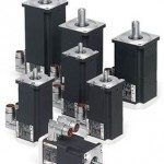
ABB Frequency Converters are used to change the frequency and magnitude of the constant grid voltage to a variable load voltage. Frequency converters are especially used in variable frequency AC motor drives.
Figure 1 shows the behavior of an induction motor with several motor input voltages. The bold blue curve represents the electrical torque as a function of rotor speed when the motor is connected directly to a constant supply network. The blue portion of the torque curve shows the nominal load region (-1…+1 [T/TN]), which is very steep, resulting in low slip and power losses. Similar motor torque behavior with other motor input frequencies can be achieved by feeding the induction motor with a frequency converter and keeping the ratio of the magnitude and frequency of the motor voltage constant. As a result, the shape of the torque curve remains unchanged below the nominal speed (constant-flux region -1…+1 [n/nN]). In the field weakening region the motor voltage is at its maximum and kept constant, resulting in the torque curves being flattened.
 Fig. 1. Operation principle of the frequency converter fed induction motor.
ABB Frequency converters can be classified according to their DC circuit structure to voltage-source (Fig. 4), current-source (Fig. 3) and direct converters (Fig. 2). With a voltage-source converter the variable frequency and magnitude output voltage is produced by pulse-width modulating (PWM) the fixed DC voltage, whereas with a current-source converter the output voltage is produced by modulating the fixed DC current. With a direct frequency converter the variable output voltage is formed directly by modulating the constant input voltage. At low voltage applications (<1000 V) the voltage-source topology is mainly used.
 Fig. 2. Main circuit of the direct converter
 Fig. 3 Main circuit of the current-source converter
Fig. 4 shows a typical voltage source frequency converter structure where a constant DC voltage is formed by using an input diode rectifier. The output voltage with variable frequency and magnitude is produced by pulse-width modulating the inverter bridge. In more sophisticated frequency converters the input diode bridge can be replaced with a PWM bridge enabling a higher DC voltage, reactive power control, nearly sinusoidal supply network currents and regenerative operation of the inverter.
 Fig. 4. Main circuit of the commonly used voltage-source frequency converter.
Fig. 5a shows the operation of the inverter bridge with two different output voltages. The desired output voltage is achieved by changing the width and polarity of the output voltage pulses. The higher the instantaneous value of the output voltage, the wider the output voltage pulse needed. Although the output voltage contains a lot of high order harmonic voltages due to the PWM, the motor current is nearly
sinusoidal since the motor inductances filter out the high order current harmonics.
Fig. 5b shows the construction of negative voltage pulses, circled in Fig.5, during one PWM period. The graphic on the right shows the switching states of the phases and the resulting U-V voltage. The graphic on the left shows the space vector presentation of the eight switching states of the voltage-source converter. These switching vectors are commonly used to achieve PWM (vector modulation). The ‘+’ and ‘-’ signs mean that the phase is connected to the positive or negative rail of the DC link respectively.
 Fig. 5a and 5b Operation of the voltage-source inverter with two different output voltage references and the principle of pulse width modulation.
To learn more about ABB Frequency Converters or to download technical information, visit the ABB Website.
Information References:
- http://www.abb.com/
- http://www.abb.us/product/ap/seitp322/9f10a1ecce40c4e7c125744b00273b98.aspx
- http://www.abb.us/product/ap/seitp322/1e3455b143130716c12573fe003cb5c1.aspx
- http://www.abb.us/product/ap/seitp322/dc47706b5b2eabd4c125748a003ac770.aspx
- http://www.abb.com/product/ap/seitp322/4867d2ef0492b020c225703f0037af4e.aspx
- http://www.abb.com/cawp/abbzh254/1e44640ddc0adad6c1256e2000432d7f.aspx#
- http://www.abb.us/Copyright.aspx?text=copyright