








Electric Motor Basics: How It Works, Types and Repair
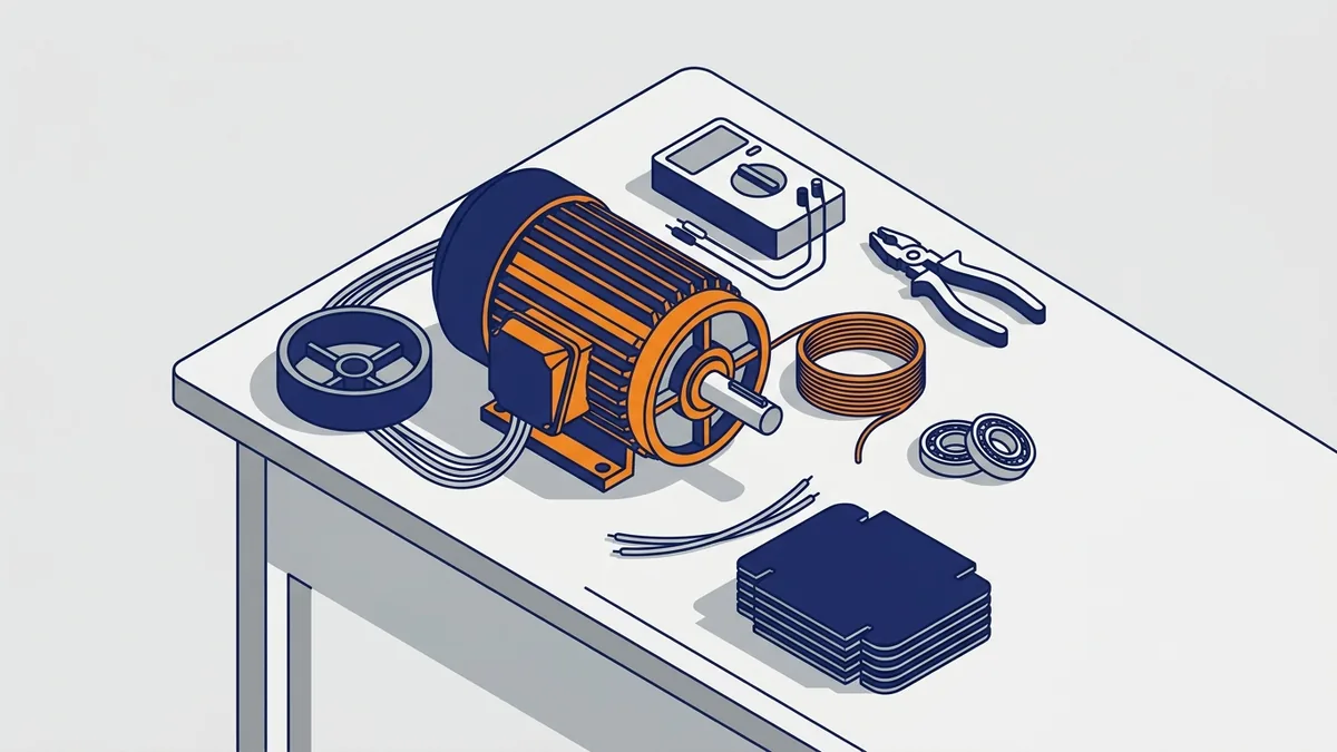
When an electric motor fails, the pump, fan or conveyor it drives stops, and so does your line. This guide explains how a motor works, which type you have, and how starters and start capacitors get it moving. You will also learn how to test and fix it, when to repair or replace it, and where to source a new motor or a rebuild.
On this page
- What an electric motor is and why it matters
- How does an electric motor work?
- Types of electric motors you will meet in a plant
- Choosing an electric motor: what to read on the nameplate
- Starting an electric motor: starters explained
- The electric motor start capacitor
- Fixing an electric motor: diagnose before you replace
- Safety first: isolate and lock out
- Which lockout/tagout, arc-flash and PPE rules apply?
- Step-by-step electric motor test sequence
- What winding resistance should a motor read?
- Insulation resistance (megger) testing
- Test voltage, 40 °C correction and IEEE 43 limits
- Trending readings and the polarization index
- Common electric motor faults and what they mean
- How do you test and repair a DC motor?
- How do you test a wound-rotor motor?
- How do you test a synchronous motor?
- Repair or replace an electric motor: when to send it to a shop
- Keeping an electric motor running: maintenance and efficiency
- Where to buy an electric motor or get documentation
- Frequently asked questions
What an electric motor is and why it matters
What is an electric motor?
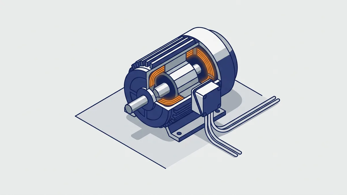
An electric motor is a machine that turns electrical energy into torque on a shaft. It does this with magnetic force between two parts. First, the stator is the stationary part, built as an electromagnet. Then the rotor is the part that spins with the shaft.
In fact, most motor types differ mainly in one way: how current reaches the moving rotor. Once you understand that, the rest of this guide falls into place.
Why do electric motors matter for plant energy use?
Motors use more electricity than any other load in most plants. However, the published shares differ by source and year, so treat them as a range.
For example, the US DOE motor and drive selection guide puts motors at roughly 60% of industrial electricity use. That same guide gives more than 70% for process industries. Also, the 2021 US DOE motor systems study, as summarised by a trade publication, reports about 69%. Finally, the IEA 4E Policy Brief #9 puts the industrial share at 72% for 2023.
Whichever figure you use, the lesson stays the same. Your choice of electric motor, starting method and repair path drives both energy cost and downtime. So this guide walks through the whole job in order. Where a topic has its own Precision Electric post, such as service factor or stator rewinds, we summarise it and point you there.
How does an electric motor work?
Here is the short answer. Current in the stator windings creates a magnetic field. That field acts on a magnetic field in the rotor, and the force between them turns the shaft. The sections below explain each step, from the basic parts to slip and single-phase starting.
The stator and rotor: how an electric motor makes torque
The stator is a stationary electromagnet. It holds copper windings set in slots of a steel core. When current flows through those windings, they form magnetic poles.
Inside the stator, the rotor sits on the shaft with a small air gap around it. The rotor also carries a magnetic field. Because opposite poles attract and like poles repel, the rotor turns to follow the stator’s field.
So the key question for any electric motor is how the rotor gets its field. Some designs feed current to the rotor through brushes. Others induce current in the rotor with no contact at all, as the next sections show.
The rotating magnetic field in a three-phase AC motor
How do electric motors work in three-phase AC systems? A three-phase supply carries three currents that peak 120° apart in time. Because each stator winding peaks in turn, the combined field sweeps around the stator like a spinning magnet. As a result, a three-phase motor starts on its own, with no extra start winding.
That field turns at a fixed rate called synchronous speed. You can work it out with this formula:
Ns = 120 × f ÷ P
Here, Ns is synchronous speed in rpm, f is supply frequency in hertz, and P is the number of poles. For example, a 4-pole motor on 60 Hz gives 120 × 60 ÷ 4 = 1,800 rpm. Likewise, a 2-pole motor on 60 Hz gives 3,600 rpm.
Induction and slip
In an induction motor, only the stator connects to the power supply. The rotating stator field crosses the air gap and cuts the rotor conductors. That action induces current in the rotor, and the rotor current builds its own field. Then the two fields interact and produce torque.
Because of this, some engineers call the induction motor a rotating transformer. The stator works as the primary, and the rotor works as the secondary. No brushes or contacts feed the rotor.
What is slip in an induction motor? Slip is the gap between rotor speed and synchronous speed, shown as a ratio: (Ns − rotor speed) ÷ Ns. The rotor must lag behind the field. Otherwise, the field would stop cutting the rotor conductors, and the motor would make no current and no torque.
That is why a 4-pole, 60 Hz nameplate shows a speed a little below 1,800 rpm. Also, rotors come in two main forms. A squirrel-cage rotor uses conducting bars shorted by end rings, and it is the most common industrial motor design. In contrast, a wound rotor uses insulated windings brought out through slip rings.
How single-phase motors get started
How does a single-phase motor start? A single-phase supply makes a field that pulses back and forth but does not rotate. As a result, a stopped rotor gets no push in either direction, so it just hums.
To solve this, the motor adds a second winding, called the auxiliary or start winding. In many motors, a capacitor in series with that winding shifts the timing of its current. Together, the two windings then create a rotating field, and the rotor starts to turn. Once the motor nears full speed, a centrifugal switch usually drops the start circuit out.
Types of electric motors you will meet in a plant
What are the types of electric motors? Most plants run a mix of four main families. Here is each one, with the job it usually does.
- Three-phase AC induction motor. This is the plant workhorse for pumps, fans, conveyors and compressors. It has one AC supply, to the stator only, and usually a squirrel-cage rotor.
- Single-phase AC induction motor. It drives smaller loads where you only have single-phase power. It needs a start winding and often a capacitor to start.
- Synchronous motor. Its speed locks to the line frequency because it does not rely on induction to create the rotor field. Some designs start as induction motors, then lock in near synchronous speed.
- DC motor. A wound-field DC motor needs a field supply and an armature supply, and brushes carry current to the armature. You will often find them on older machines that need wide speed control.
Single-phase electric motor types compared
Single-phase motors differ mainly in how they start. This table compares the three common types.
| Type | How it starts | Starting torque | Typical uses |
|---|---|---|---|
| Split-phase | Start winding with no capacitor, switched out near speed | Lower than capacitor-start types | Light, easy-starting loads |
| Capacitor-start | Start capacitor in series with the start winding, switched out near speed | High (one supplier guide quotes 200–300%) | Air compressors, deep-well pumps, conveyors |
| Capacitor-start/capacitor-run | Start capacitor for starting, plus a run capacitor that stays in | High, with smoother running | Heavy machinery, large HVAC compressors |
In short, split-phase motors handle easy starts, while capacitor designs handle hard ones. For a full look at AC and DC designs, see our posts Difference From AC and DC Electric Motors and AC DC Industrial Electric Motors.
Choosing an electric motor: what to read on the nameplate
What do I need from the nameplate to choose or replace a motor? Start with the nameplate itself, then confirm each value with the manufacturer’s data sheet. Never guess ratings from the motor’s size or color. Record these items:
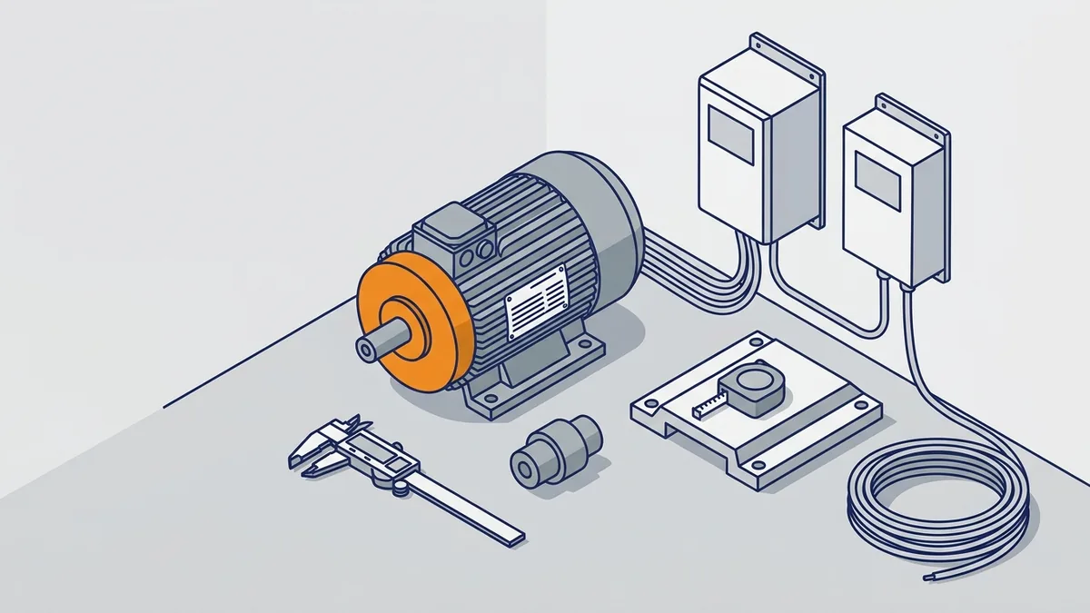
- Voltage, phase and frequency (Hz)
- Horsepower or kW
- Full-load speed (rpm)
- Full-load current (amps)
- Enclosure type, such as open drip-proof or totally enclosed fan-cooled
- Frame designation, which sets mounting and shaft dimensions
- Service factor, the extra load the maker says the motor can carry above its rating
- Insulation class and duty rating
Frame sizes and ratings follow published standards. So for exact dimensions or limits, use the manufacturer’s data or NEMA’s published standards rather than memory.
How do you read a NEMA or IEC frame size?
The frame number tells you the mounting and shaft size. In a NEMA three-digit frame, the first two digits divided by 4 give the shaft centerline height in inches. For example, a 143T frame stands 3.5 in. from the base to the shaft centerline. The last digit sets the body length. The letter T means standardized shaft dimensions, and suffixes such as C or D mark face or flange mounting.
This table lists common NEMA T-frames. Always confirm against NEMA MG 1 or the maker’s data sheet before you order.
| NEMA frame | Shaft height (D) | Shaft diameter |
|---|---|---|
| 143T, 145T | 3.5 in. | 7/8 in. |
| 182T, 184T | 4.5 in. | 1-1/8 in. |
| 213T, 215T | 5.25 in. | 1-3/8 in. |
| 254T, 256T | 6.25 in. | 1-5/8 in. |
| 284T, 286T | 7.0 in. | 1-7/8 in. |
| 324T, 326T | 8.0 in. | 2-1/8 in. |
IEC frames work differently. The frame number is the shaft height in millimeters, so a 90 frame has a 90 mm shaft height. Mounting codes then describe the style, such as B3 for foot mounting and B5 or B14 for flange types.
Match the industrial motor to the real load
Next, size the motor for the real load, not just the old motor’s rating. An oversized motor runs lightly loaded and wastes energy. The US DOE BestPractices guide on motor-driven systems lists three key steps. Match motors to the load, match motors and drives, and pick energy-efficient or premium-efficiency replacements.
Also, tell your supplier whether a VFD will power the motor. Drive duty affects insulation and cooling choices. Our posts Electric Motor Service Factor and AC Electric Motor Speed Control cover both topics in depth.
Starting an electric motor: starters explained
What is a starter for an electric motor? In industry, a starter electric motor setup is the control gear that connects the motor to power and limits starting stress. It usually includes overload protection as well. Automotive starter motors, which crank engines, are a different subject that this guide does not cover.
Starting is the hardest moment in a motor’s working life. At full voltage, current surges far above running current, and the shaft gets a sudden torque kick. So the starter decides how much of that stress the motor, the load and the supply must absorb.
Starter types compared
| Starter type | Starting current | Starting torque | Best use |
|---|---|---|---|
| Direct-on-line (DOL) | About 6–8 × full-load current | Full torque | Small machinery and pumps on a supply that can take the dip |
| Star-delta | About one-third of DOL | About one-third of DOL, fixed | Large motors with heavy starting current and light starting loads |
| Soft starter | Reduced, set by an adjustable voltage ramp | Reduced, adjustable | Smooth starts for pumps, fans and belt conveyors |
| VFD | Limited and controlled by the drive | Controlled by the drive | Loads that need precise speed control |
Schneider Electric’s guide, Different Types of Motor Starters, also lists autotransformer starters as another reduced-voltage option.
Direct-on-line (DOL) starters
A direct-on-line starter is the simplest choice. It uses one contactor and an overload relay and puts full voltage on the motor at once. As a result, inrush current runs about 6 to 8 times full-load current.
DOL suits small motors and loads where the supply can handle the voltage dip. However, the sudden torque can stress belts, couplings and gearboxes. In addition, makers design a standard AC-3 DOL starter for infrequent starting, not constant cycling.
Star-delta starters
A star-delta starter runs the motor in star (also called wye) to start, then switches to delta. In star, each winding sees lower voltage, so starting current drops to about one-third of DOL. However, starting torque also drops to about one-third. After roughly 5 to 10 seconds, a timer swaps the motor into delta for full running.
This method needs a 6-lead motor brought back to the panel, three contactors and a timer. Watch for two common mistakes:
- Switching too early. If the timer moves to delta before the motor reaches about 80% of rated speed, the current spike can be nearly as bad as a DOL start.
- Using it on heavy loads. With only one-third torque, a high-inertia load may never accelerate in star.
Soft starters and VFDs
A soft starter uses SCRs, which are solid-state switches, to ramp the voltage up over a set time. Ramp times of 5 to 30 seconds are typical. Because the ramp is smooth, you get no transition spike like a star-delta changeover. Many soft starters also offer soft stop, which reduces water hammer in pump lines.
Also, a standard soft starter needs only the 3-lead connection at the motor. For setup detail, the ABB Softstarter Handbook is a good free reference.
A VFD (variable frequency drive) changes both voltage and frequency. So it gives you a soft start plus full speed control. One supplier guide advises an input line reactor on cable runs over about 100 ft and a dv/dt filter to protect winding insulation. Check your drive manual for the exact rules, and see our AC Electric Motor Speed Control post for more.
How do you match an electric motor to a VFD?
A VFD changes how the motor lives, so check four things before you pair them.
- Insulation. A drive sends fast voltage pulses that stress the windings. Choose an inverter-duty motor, which NEMA MG 1 Part 31 covers, for drives on 600 V or less. That standard asks for insulation that withstands 1,600 V peak pulses. Standard motors can work on gentle drive setups, but ask the maker first.
- Bearing currents. Drive output can push current through the bearings, which pits and flutes the races. To stop this, add a shaft grounding ring, an insulated bearing (usually at the non-drive end) or a common-mode filter. Larger frames carry more risk. Also use proper VFD cable and ground it well.
- Cable length. Long cables make voltage spikes at the motor worse. The safe length depends on the drive, its carrier frequency and the motor insulation, so use the drive manual. To reach farther, add an output reactor, a dv/dt filter or a sine filter.
- Minimum speed. A shaft-mounted fan slows down with the motor. As a result, a constant-torque load at low speed can overheat it. Fix this with an auxiliary constant-speed blower, a derated load or a larger motor.
Finally, size the drive to the motor’s full-load amps, not just its horsepower.
How many starts per hour can a motor take?
No single number fits every motor. Each start heats the rotor and stator far more than normal running does. So the limit depends on the motor, the load inertia and the time between starts.
NEMA MG 1 sets a baseline for standard motors. A motor should handle two starts in a row from ambient temperature, coasting to rest between them. It should also handle one start when it is already at operating temperature. That rule applies only within the load inertia limits in the standard.
For your motor, ask the manufacturer for the allowed starts per hour and the minimum rest time. The nameplate rarely lists them. If the load has high inertia, ask for a thermal limit curve. Then count the real starts and compare.
How to pick a starting method
Which starter electric motor setup suits your load: DOL, star-delta, soft starter or VFD? Use these rules as a starting point, then confirm with the motor and starter makers.
- Small motor, strong supply, few starts: DOL is the simple, proven choice.
- Large motor, light starting load, 6-lead motor: star-delta works. It costs less than electronic starters and makes no harmonics, but torque is fixed at one-third.
- High-inertia or heavy-start load: skip star-delta and use a soft starter or VFD sized for the duty.
- Pumps with water hammer: pick a soft starter with soft stop.
- Generator supply: a 10 HP motor started DOL on a 20 kW generator can stall the engine. A soft starter or VFD keeps inrush under the generator’s surge rating.
- Frequent starts: random overload trips after about 20 minutes of running can mean too many starts per hour. Check the motor’s limit and choose a starter rated for the duty.
- Need speed control: use a VFD.
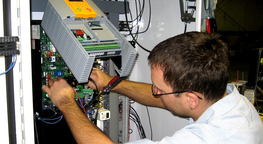
If a drive or soft starter fails, see our drive repair post, or send the unit to our shop for testing.
The electric motor start capacitor
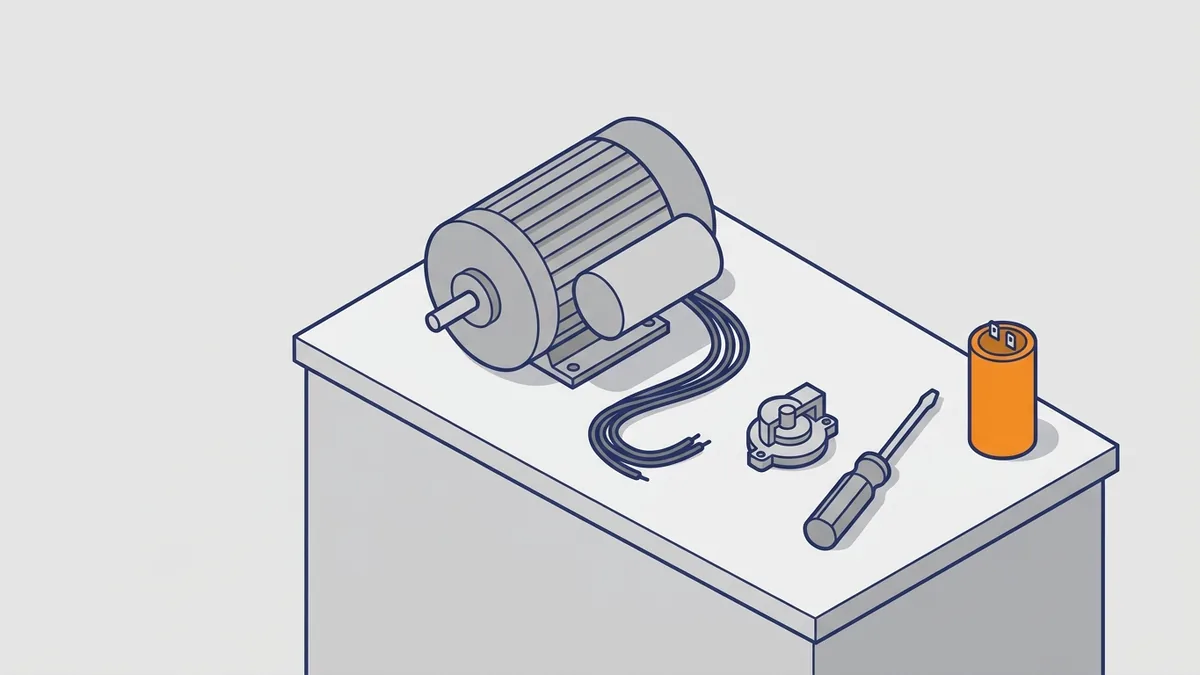
What does an electric motor start capacitor do? It shifts the current in the start winding of a single-phase motor. That shift creates a rotating magnetic field, so the motor can start, often under load. However, if the start switch stays open, the capacitor never enters the circuit and the motor will not start.
Start capacitor vs run capacitor
What is the difference between a start capacitor and a run capacitor? A start capacitor has a large capacitance, measured in microfarads (µF). It stays in the circuit for only a few seconds, then a switch removes it. Because it cannot handle continuous current, never use one as a run capacitor.
A run capacitor, by contrast, stays in the circuit the whole time the motor runs. It has lower capacitance and improves running performance. Some motors use a dual run capacitor, which holds two values in one can. Meanwhile, capacitor-start motors deliver high starting torque, so they suit compressors, deep-well pumps and conveyors.
Symptoms of a bad start capacitor
How do you know if the electric motor start capacitor is bad? Watch for these signs:
- The motor hums but will not start.
- Starting is slow, or the shaft struggles to reach speed.
- The breaker or overload trips during starting.
- Heat builds up while the motor runs.
However, test before you replace anything. A stuck centrifugal switch, an open start winding or bearing trouble can look exactly the same. So also check that the shaft turns freely by hand, with power locked out.
How to test a motor start capacitor
How do I test an electric motor start capacitor? Follow these steps in order:
- Lock out and tag out the circuit, turn the breaker off, and verify the circuit is dead.
- Discharge the capacitor through a resistor before you touch the terminals. One supplier guide uses a 20 kΩ resistor.
- Check for a bleed resistor across the tabs. Alabama Cooperative Extension says to unsolder one leg before you measure.
- Measure the µF with a capacitance meter and compare it to the label.
- Check the start switch for continuity, since it can fail too.
Sources disagree on the pass window. For example, Alabama Cooperative Extension allows ±20% for start capacitors and ±10% for run capacitors. One capacitor supplier also uses ±20% for start, but a tighter ±5% for run. Another troubleshooting guide suggests a reading within 10% of rating, so follow the capacitor label or the motor manufacturer.
How to replace a start capacitor and why the value matters
When you replace it, match the original µF exactly, and use the same or a higher voltage rating. Also, skip horsepower sizing charts and copy the nameplate or the original part. AC motor capacitors are non-polarized, so terminal order on a standard single capacitor does not matter.
Why does the value matter so much? A start capacitor that is too small reduces starting torque, speed and efficiency. One that is too large can do the same and overheat the windings with extra current. Likewise, a wrong run capacitor makes the field irregular, so the motor may hesitate under load, run noisily and overheat.
Fixing an electric motor: diagnose before you replace
Fixing an electric motor starts with one question: is the fault in the motor at all? Many “dead” motors turn out to have supply, starter, drive, load or mechanical problems. So rule those out first, and you can fix electric motor faults with evidence instead of guesswork. Our troubleshooting tools post lists the meters that help.
Safety first: isolate and lock out
What safety steps come before fixing an electric motor? Never open or test a live circuit as a shortcut. Instead, follow this order every time:
- Isolate the motor at its disconnect and apply lockout/tagout.
- Verify zero voltage with a properly rated tester.
- Discharge any capacitors through a resistor.
- Disconnect the motor leads from VFDs, soft starters and control circuits before megger testing. The test voltage can damage them or skew your results.
- Secure the load so the shaft cannot turn on its own, for example from a fan windmilling.
Which lockout/tagout, arc-flash and PPE rules apply?
In the US, OSHA 1910.147 covers the control of hazardous energy, which means lockout/tagout. It requires a written energy control program, trained workers and periodic inspections of the procedure. OSHA 1910.333 covers safe work practices around electrical equipment. In addition, NFPA 70E, the Standard for Electrical Safety in the Workplace, explains how to reach an electrically safe work condition.
A verified-dead procedure under those rules follows this pattern:
- Identify every source of power, including control and backfeed sources.
- Open the disconnect and visually confirm the blades are open where you can.
- Apply your lock and tag.
- Release stored energy, such as capacitors and spring-loaded parts.
- Test your meter on a known live source, test the circuit, then test the meter again.
PPE depends on your arc-flash risk assessment and equipment labels. It often includes arc-rated clothing, a face shield, safety glasses, hard hat, hearing protection, insulated gloves with leather protectors and rated footwear. Only a qualified person should work near energized parts. Check your plant’s written program for the exact gear.
Step-by-step electric motor test sequence
How do I fix an electric motor? Use this order, which moves from simple checks to deeper tests.
- Inspect it. Turn the shaft by hand. Then check bearings, coupling, alignment, debris, burnt smells and damaged leads.
- Measure winding resistance. Read between each pair of phases. The readings should be balanced, and a mismatch points to a shorted or open winding.
- Test insulation resistance. Megger each winding to ground, as described below. Shops may add a hipot test.
- Run and measure. A qualified person checks voltage and current on each phase against the nameplate, under light and full load, following plant safety rules. Also watch power factor and temperature.
One fault can hide from all of these tests. Surge testing finds turn-to-turn shorts that insulation and hipot tests may miss. Because it needs a dedicated surge tester, it is usually a motor shop job.
What winding resistance should a motor read?
Winding resistance is very low, often a few ohms or less, and big motors read in milliohms. A basic multimeter cannot read it well, so use a low-resistance ohmmeter. The right value depends on the motor’s horsepower, voltage and winding, so no single figure fits all.
Instead, compare your readings in two ways. First, compare the three phases to each other. Second, compare them to the manufacturer’s data, a shop record or a known good identical motor.
To find the imbalance, average the three readings. Then divide the biggest difference from that average by the average, and multiply by 100. Many shops flag a spread above about 5%, and some use a tighter limit. Also note that copper resistance rises about 0.4% per °C, so record winding temperature and compare readings taken at similar temperatures.
Insulation resistance (megger) testing
How do I megger test a motor, and what reading is acceptable? An insulation tester, often called a megger, applies a high DC voltage and measures leakage to ground. A standard multimeter cannot do this, because it does not apply enough voltage.
- Record winding temperature, ambient temperature and humidity first.
- Tie the three motor leads together and connect them to the tester’s line lead.
- Clip the ground lead to bare metal on the frame, not paint.
- Apply the test voltage for one minute and record the reading. Pick the voltage from the table in the next section.
Older rules of thumb differ. One source treats 10 MΩ or more as fine for new, cleaned or repaired windings, and 2 MΩ or less as bad. Another, used by Southwest Electric, gives 1 MΩ per 1,000 V of rated voltage, with a 1 MΩ minimum. So use the IEEE 43 limits below, or your manufacturer’s limit and plant standard.
Test voltage, 40 °C correction and IEEE 43 limits
IEEE 43 is the standard for testing insulation resistance on rotating machines. It ties the test voltage to the winding’s rated voltage.
| Winding rated voltage | DC test voltage |
|---|---|
| Below 1,000 V | 500 V |
| 1,000–2,500 V | 500–1,000 V |
| 2,501–5,000 V | 1,000–2,500 V |
| 5,001–12,000 V | 2,500–5,000 V |
| Above 12,000 V | 5,000–10,000 V |
Insulation resistance falls as temperature rises. As a rule, it roughly halves for every 10 °C increase. To correct a reading to 40 °C, multiply it by 0.5 raised to the power of (40 − T) ÷ 10, where T is the winding temperature in °C. For example, 20 MΩ at 30 °C becomes 10 MΩ at 40 °C.
IEEE 43 then gives these minimums for the 1-minute reading, corrected to 40 °C. Here, kV means the rated line-to-line voltage in kilovolts.
| Winding type | Minimum insulation resistance |
|---|---|
| Older form-wound (before about 1970), all field windings, and others not listed | kV + 1 MΩ |
| Form-wound made after about 1970 | 100 MΩ |
| Random-wound, and form-wound rated below 1 kV | 5 MΩ |
For the polarization index below, IEEE 43 sets a minimum of 2.0 for common thermal classes B, F and H.
Trending readings and the polarization index
A single reading tells you less than a trend does. New machines often read in the thousands of megohms. So a steady drop over several tests matters more than one number on a single day.
Also, the polarization index (PI) compares readings at 1 minute and 10 minutes. A healthy winding keeps rising over those 10 minutes. However, if the 1-minute reading is above about 5,000 MΩ, the PI may not mean much.
Common electric motor faults and what they mean
What are common electric motor faults and their causes? Typical failure modes include insulation breakdown, winding shorts, bearing wear, rotor imbalance and overheating from overload. Use this table to link a symptom to its likely cause and your next check.
| Symptom | Likely causes | Next check |
|---|---|---|
| Hums but will not start (single-phase) | Failed start capacitor, stuck centrifugal switch, open start winding | Test capacitor µF, switch continuity and start winding resistance |
| Hums but will not start (three-phase) | Missing phase in the supply or starter, seized bearing, jammed load | Turn the shaft by hand with power locked out, then have all three supply phases checked |
| Trips the overload | Overloaded machine, too many starts per hour, wrong capacitor value, shorted winding | Compare running current to nameplate, count starts, check winding balance |
| Runs hot | Overload, wrong start or run capacitor value | Measure running current, check capacitor values against the label |
| Noisy or vibrating | Bearing wear, rotor imbalance, wrong run capacitor value | Check bearings, coupling and alignment, then test the run capacitor |
| Trips a ground fault | Insulation breakdown | Megger each winding to the frame |
How do you test and repair a DC motor?
A DC motor adds brushes, a commutator and a field supply to the checks above. Start with the brushes. Compare their length to the maker’s minimum, check spring pressure, and look for chipping or uneven wear. Sparking at the brushes is a warning sign.
Next, inspect the commutator. A healthy surface is smooth, with an even brown film. Grooves, flat spots, burnt bars or high mica need a shop to turn and undercut it. Then test the armature for shorted or open coils, and megger the armature and field windings to ground.
Finally, check the field supply. A shunt-wound motor that loses its field can overspeed, so confirm field voltage, polarity and wiring before you run it.
How do you test a wound-rotor motor?
Test the stator as you would an induction motor. The rotor needs extra checks because its windings connect to slip rings. Inspect the rings for grooves, glazing and burns, and check the brushes and brush lift gear for wear.
Next, megger the rotor winding through the slip rings, with the external resistor bank disconnected. Then check the resistor bank for open elements, and test the contactors that cut resistance in and out. Poor starting or low torque often traces back to this external gear.
How do you test a synchronous motor?
Test the stator the same way as an induction motor. The rotor has a DC field winding, so measure its resistance and megger it to ground. Check the damper windings, which help the motor start, for broken bars or loose connections.
Then check the field supply. Some motors use slip rings and brushes, so inspect them like those on a wound-rotor motor. Others use a brushless exciter with rotating diodes, so test the diodes. Confirm field current against the nameplate, and apply the field only as the maker directs.
Repair or replace an electric motor: when to send it to a shop
Should I repair or replace an electric motor? Your test results usually decide for you. Some faults are quick fixes, while others point to a rewind or a new motor.
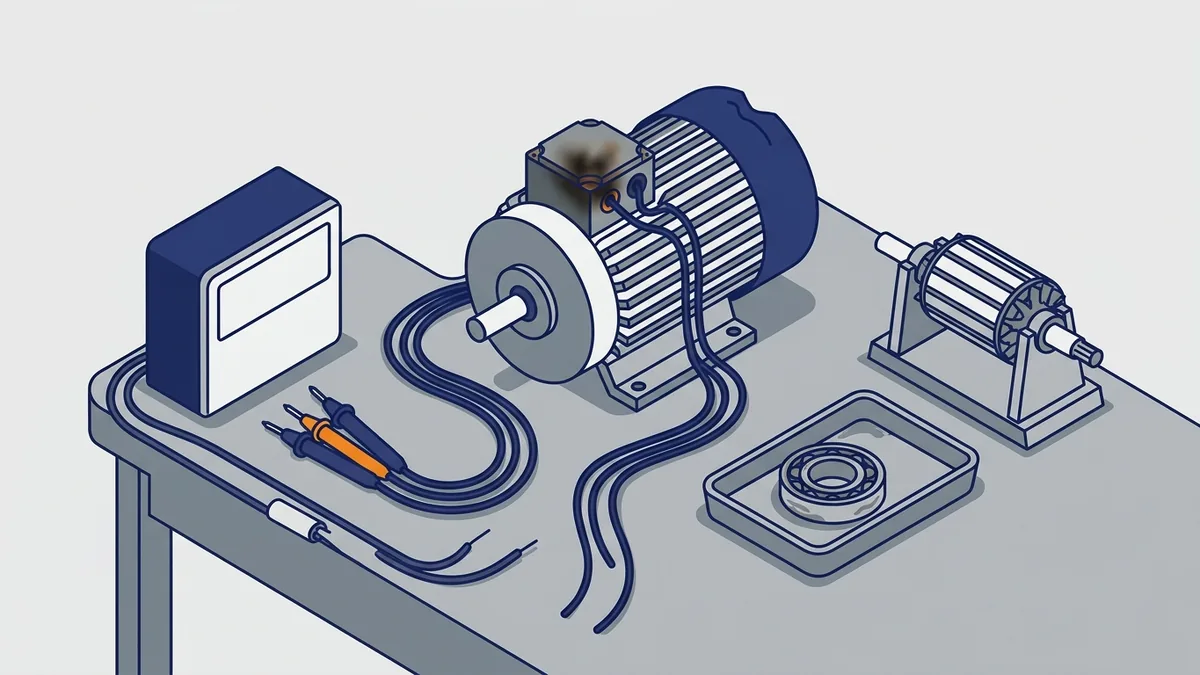
Simple fixes you can often do in place
- A failed start or run capacitor
- A stuck centrifugal start switch
- Worn bearings
- Starter, contactor or overload relay faults
- Supply, coupling or alignment problems outside the motor
Signs you need a rewind or replacement
- A surge test shows turn-to-turn shorts.
- Insulation resistance is low or keeps falling over time.
- Winding resistance is unbalanced between phases.
- The same motor fails again and again.
Also, think about energy when an older motor fails. The US DOE suggests premium-efficiency replacements, which can make sense for motors that run long hours. Our posts on stator winding repair, DC motor repair and our commercial and industrial motor repair guide explain each repair path.
What rule decides repair or replace?
Many plants use a cost rule of thumb. If the repair quote reaches about 50 to 60 percent of a new motor’s price, they lean toward replacement. This is a common guide, not a standard, so treat it as a starting point.
Then adjust for the facts. A motor that runs long hours may repay a premium-efficiency unit through lower power bills. A large, special or hard-to-find motor may favor repair. Also weigh how long you can afford to be down, because new motor lead times vary by model and supplier. Ask for current stock and lead time with your quote.
What does it cost to repair an electric motor, and how long does it take?
Cost depends on frame size, voltage, motor type and the damage found inside. Turnaround also depends on parts and the scope of work. So we do not publish flat prices or set lead times. Instead, Precision Electric quotes after inspection and teardown testing, so you see the real scope before you approve any work.
Local motor rebuilds in Northern Indiana
We offer full local motor rebuilds in our 32,000 square foot facility in Mishawaka, Indiana. That means one shop can test, diagnose and rebuild your motor. Then you can compare the rebuild quote with a new motor before you decide.
Keeping an electric motor running: maintenance and efficiency
How do I keep an electric motor running longer? Regular checks catch problems while they are still cheap to fix. Use this routine as a base, then adjust it to your plant.
- Run routine tests on a set schedule, and test critical 24/7 motors more often.
- Log insulation resistance with temperature and humidity, and watch the trend.
- Check running current and voltage balance against the nameplate.
- Listen for bearing noise, check for heat and vibration, and lubricate as the manufacturer directs.
- Keep the motor clean and its cooling path clear.
- Respect the starts-per-hour limit, and match the starter to the load.
Why efficiency and correct sizing pay back
Motor systems are the largest electricity use in industry, as the DOE and IEA 4E figures above show. As a result, small gains add up fast across a plant. Right-sizing a motor, pairing it with the right drive and choosing a premium-efficiency replacement all cut running cost. The US DOE BestPractices guide on motor-driven systems walks through each step.
Where to buy an electric motor or get documentation
Where can I buy an electric motor or get a rebuild? Precision Electric distributes many brands of electric motors nationwide through our webshop, with free ground shipping. We also offer full local motor rebuilds at our facility in Northern Indiana.
What to have ready when you order
- A clear photo of the nameplate
- Frame designation
- Voltage, phase and frequency
- Horsepower or kW
- Full-load RPM
- Enclosure type
- Whether a VFD or soft starter will power the motor
Where to find manuals and references
Start with the manufacturer’s manual for your exact electric motor. It lists the wiring, lubrication and test limits that apply to your unit. For background, these free references help:
- US DOE (EERE) electric motor and drive selection guide, for motor types and matching motors and drives to applications
- US DOE Industrial Technologies Program BestPractices guide, Motor-Driven Systems, for efficiency steps
- ABB Softstarter Handbook, for soft starter setup
- Schneider Electric’s Different Types of Motor Starters, for starter basics
- Alabama Cooperative Extension’s Testing a Motor Capacity, for capacitor checks
- NEMA’s US Industrial and Commercial Motor System Market report, plus NEMA’s motor standards for frame and rating details
- IEA 4E Policy Brief #9 on electric motor systems, for energy-use context
Frequently asked questions
How does an electric motor work?
Current in the stator windings creates a magnetic field. In a three-phase AC induction motor, that field rotates and induces current in the rotor. The rotor’s own field then interacts with the stator field to produce torque. Because no current flows without a speed difference, the rotor runs slightly slower than the field, which is called slip.
How do electric motors work without touching the rotor?
In an induction motor, only the stator connects to power. The changing stator field induces rotor current by transformer action, so no brushes or contacts feed the rotor. Wound-field DC motors, however, do feed the armature through brushes.
What does an electric motor start capacitor do?
In a single-phase motor, it shifts the current in the start winding so the motor makes a rotating field and gets high starting torque. It stays in the circuit for only a few seconds, so you cannot use it as a run capacitor. A motor that hums but will not start often has a failed start capacitor. However, a stuck centrifugal switch or open start winding looks the same, so test first.
How do I fix an electric motor that won’t start?
Lock out power, then separate motor faults from supply, starter and load faults. Next, check that the shaft turns freely, measure winding resistance between phases, and run a megger test. On a single-phase motor, test the capacitor and start switch, and have voltage and current checked against the nameplate. If the windings are unbalanced, grounded or shorted, repair or replace the motor.
What are the main types of motor starter?
The main types are direct-on-line (DOL), star-delta, soft starter and VFD. DOL is the simplest but draws high inrush current. Star-delta and soft starters reduce starting stress, and a VFD adds speed control.
An electric motor is simple at heart: a stator field pulls a rotor around. Most problems trace back to the supply, the starter, the start capacitor, the bearings or the windings, and a clear test order shows you which. So test first, follow the nameplate and the manufacturer, and keep a record of every reading. If you need a replacement electric motor, a repair quote or a full rebuild, contact Precision Electric or browse the motors on our webshop.