Motor VFD Drive: Practical Guide To Selection and ROI

Estimated reading time: 6 minutes
Introduction
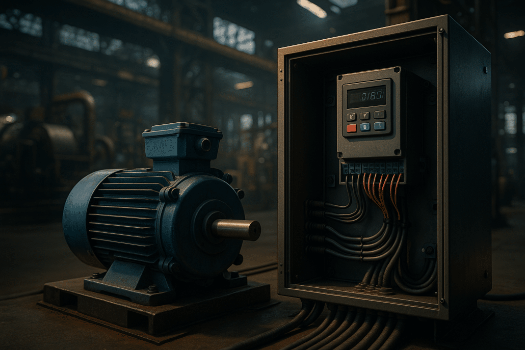
A motor vfd drive—often called a variable frequency drive or ac drive—controls motor speed by varying output frequency and voltage. Consequently, it matches power to process demand, which reduces energy use, improves quality, and extends equipment life. Additionally, modern inverters provide soft start/stop, torque control, built‑in PID, fieldbus connectivity, and safety functions such as Safe Torque Off (STO). Moreover, installation teams can deploy drives in existing panels or motor control centers with minimal wiring changes. Therefore, VFDs have become the default approach for pumps, fans, conveyors, mixers, and material handling.
For fundamentals, ABB’s Technical Guide to Variable Speed Drives explains rectifier–DC link–inverter topology and PWM. Likewise, overviews from Digi-Key and RealPars clarify how a vfd motor controller converts fixed mains into adjustable output. As a result, plant teams can optimize flow, pressure, and tension without mechanical throttling.
How a Motor VFD Drive Works and Why It Solves Fixed‑Speed Losses
Most losses in constant‑speed systems come from throttling devices and unnecessary friction. However, a motor vfd drive eliminates those losses by scaling speed to demand. Additionally, VFDs apply V/Hz or vector control to maintain torque across the speed range. For example, sensorless vector maintains tight speed regulation at low rpm, while field‑oriented control responds rapidly to load swings. Furthermore, ABB’s Direct Torque Control (DTC) demonstrates how advanced estimators directly manage flux and torque for fast dynamics, reducing scrap on lines that need quick speed changes. In practice, teams set acceleration and deceleration ramps to avoid mechanical shocks, then use integrated PID to hold pressure or flow without valves.
Because fans and pumps follow affinity laws, trimming speed by 20% can roughly halve power. Therefore, drives often pay for themselves quickly when retrofitting dampers or bypass valves. For reference cases, see Precision Electric’s guide to energy results in blowers and pumps and our broader VFDs guide and VFDs for pumps. Moreover, if you want a quick programming overview before commissioning, review our VFD programming guide and auto‑tune walk‑through to shorten start‑up time.
Solving Common VFD Problems With Practical Field Fixes
Technicians frequently face overvoltage on decel, nuisance overcurrent trips, and thermal derating. Accordingly, configure ramps so regenerative energy does not spike the DC bus; add a braking resistor or a regen unit if fast stopping is mandatory. Additionally, size the drive for heavy‑duty overload when the application includes frequent starts or cyclic torque peaks. Moreover, check motor nameplate amps and set the electronic overload inside the vfd controller to guard against overheating. For deeper fault coverage, see our cornerstone troubleshooting articles on overvoltage on deceleration, overcurrent and overload, and overheating and cooling failures.
Cable length and reflected wave spikes can stress insulation, particularly at 480 V. Consequently, use inverter‑duty motors that meet NEMA MG1 Part 31; consult the NEMA listing for MG‑1 Motors and Generators. Additionally, add dV/dt or sine‑wave filtering for very long runs. Furthermore, bond shields at both ends and separate power from control wiring to improve EMC. When commissioning, run auto‑tune, validate motor direction, and log trip codes. As a result, you’ll stabilize the system quickly while protecting bearings and windings.
Engineering and Standards for AC Drives: Power Quality, Safety, and EMC
Line‑side harmonics rise because rectifiers draw pulsed current. Therefore, plan mitigation early. Additionally, IEEE 519 defines distortion limits at the point of common coupling; review the IEEE 519‑2014 overview when sizing chokes and filters. Moreover, DC bus chokes or input reactors reduce current distortion; active front ends push harmonics even lower and hold near‑unity displacement power factor. Consequently, large multi‑drive rooms benefit from a facility‑level assessment.
Functional safety matters as much as efficiency. Accordingly, most modern inverters include Safe Torque Off. For design and validation guidance, consult ABB’s STO application note for ACS/ACQ families: Safe Torque Off Application Guide. Additionally, Rexel summarizes practical use cases in a concise field article on when to use STO. Furthermore, follow UL/IEC safety requirements for adjustable‑speed drives (e.g., UL/IEC 61800‑5‑1) and verify EMC practices per IEC 61800‑3 during panel build and site testing.
Selecting a Motor Inverter: Manufacturer Differences That Matter
Although most ac motor drive platforms share core functions, several traits influence success on the floor. First, control algorithms differ: ABB’s DTC and comparable vector schemes improve low‑speed torque and response. Second, ease of use affects commissioning time; Yaskawa, Eaton, Hitachi, and Lenze emphasize quick start menus and macro setups. Additionally, support ecosystems—spares, software, and drive‑MCC packaging—determine life‑cycle cost. For a balanced introduction to fundamentals and options, study ABB’s technical guide above and the VFD encyclopedia entry for broad context, then apply Precision Electric’s step‑by‑step resources linked here.
Because selection and wiring details impact reliability, review our cornerstone content before buying: start with the types of VFDs overview, then validate I/O and control signals with our control wiring checklist, and finally keep a copy of our obsolete drive replacement guide for uptime planning. Additionally, if you need a refresher on autotune and PI/PID loops, the earlier links streamline setup. Consequently, your vfd speed controller will meet performance targets without trial‑and‑error.
Product Recommendations and Shortlist Links
To move from research to action, start with our core product categories. For general‑purpose applications, browse AC Variable Frequency Drives. Additionally, when a site requires soft starting without speed control, compare Soft Starters. Moreover, for single‑phase facilities that must power three‑phase motors, evaluate VFD Phase Converters. Because harmonic mitigation protects the electrical system, specify Input Line Reactors and Output/Load Reactors where needed. Consequently, these categories cover most use cases from pumps and fans to indexing conveyors.
If you’d like help pairing a motor vfd drive with a motor and line components, contact Precision Electric. Additionally, our team cross‑references lead times and panel constraints and balances cost with performance. Furthermore, we provide application‑level settings so your inverter drive meets efficiency, noise, and torque requirements on day one.
Conclusion
A properly sized motor vfd drive saves energy, stabilizes processes, and reduces mechanical stress. Additionally, attention to wiring, filters, and commissioning ensures long service life. Moreover, adherence to IEEE, NEMA, UL, and IEC guidance keeps power quality high and safety margins intact. Therefore, whether you run HVAC, water, packaging, or general manufacturing, a modern vfd for motors remains one of the fastest, lowest‑risk productivity upgrades available.
Before you buy, review Precision Electric’s cornerstone resources, then use the product links above to source components. Finally, leverage manufacturer documentation—such as the ABB guide—and reputable primers from Digi‑Key and RealPars—to validate design decisions. Consequently, your motor inverter project will hit performance targets with predictable ROI.


