VFD Motor: How To Specify, Install And Optimize
What Is A VFD Motor?
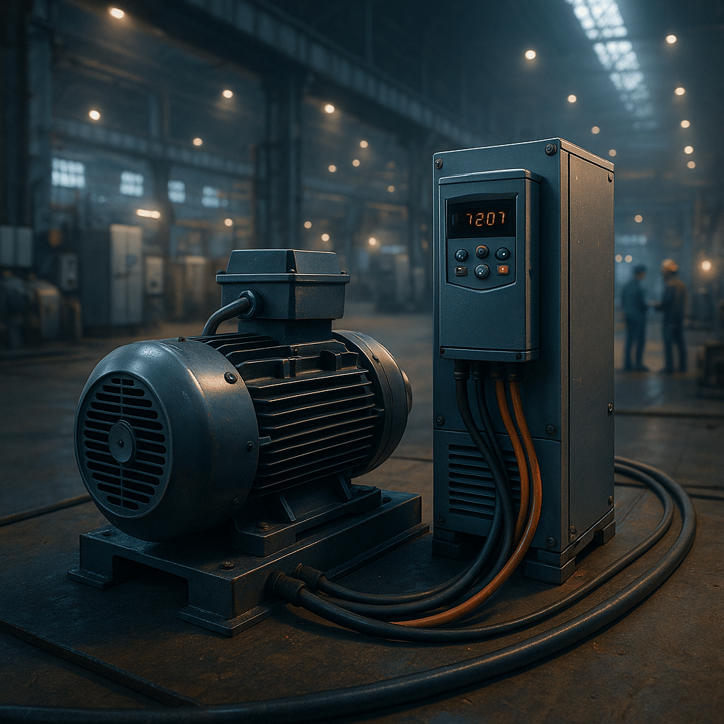
A VFD motor system pairs an AC motor with a variable frequency drive so speed and torque match the process instead of the mains. In practice, the drive rectifies line power to DC and inverts it back to PWM‑modulated AC at the commanded frequency and voltage. Consequently, the motor runs only as fast as the load requires. Which improves efficiency, reduces mechanical stress, and enables soft‑start and soft‑stop. For a concise manufacturer overview of how a VFD controls frequency, voltage, and torque, see Danfoss’ “What is a variable frequency drive?”. In high‑speed applications, some platforms can even deliver 400–1000 Hz output (for purpose‑built spindles). Yaskawa documents 1000 Hz capability in its application supplements (GPD 515 / 1000 Hz, V1000 supplement).
Because a drive can regulate volts‑per‑hertz, it preserves motor flux across the speed range. As a result, processes that previously depended on throttling or dampers now save energy by trimming speed directly. Moreover, modern drives expose diagnostics over common networks (e.g., EtherNet/IP and Modbus TCP).Sso teams can trend current, temperature, and fault histories to prevent downtime. To go deeper on configuration and commissioning, our internal guide explains parameter structures and shortcuts in plain language. See the VFD Programming Guide and related resources on drive types.
How A VFD Motor Works: AC–DC–AC Conversion
Internally, a VFD performs three core steps: rectify AC to DC, stabilize the DC link with capacitors/inductors. Also to invert DC back to variable‑frequency AC via IGBTs using pulse‑width modulation. The motor’s inductance filters the pulses, leaving a near‑sinusoidal current at the commanded fundamental frequency. A scalar (V/Hz) mode maintains a constant V/Hz ratio for general duty. While vector control and field‑oriented control improve low‑speed torque, speed regulation, and transient response. Additionally, some vendors offer direct torque control for rapid torque changes without an encoder. Our research PDF covers these controls, constant‑torque vs. variable‑torque profiles, and constant‑horsepower operation above base speed (field weakening).
On the input side, six‑pulse rectifiers produce characteristic current harmonics, so facilities with many drives should evaluate mitigation. The industry benchmark is IEEE 519’s limits at the point of common coupling. ABB’s technical note on IEEE 519‑2022 updates and Eaton’s harmonics application brief clarify application. Where needed, line reactors, passive/active filters, 12/18‑pulse rectifiers, or active front ends can reduce THDi and improve true power factor. For efficiency classification under EN/IEC 61800‑9‑2. Rockwell’s Drives Efficiency Calculator shows how vendor losses compare at the 90% speed/100% torque test point.

Common Risks And Practical Solutions
Fast PWM edges can produce reflected voltage peaks at the motor, especially on long leads. Therefore, specify inverter‑duty motors that align with NEMA MG1 Part 31 insulation guidelines and consider dV/dt or sine‑wave filters for long cable runs. From a maintenance lens, watch thermal loading at low speed: self‑cooled frames move less air. If the application dwells at low RPM, derate or add a constant‑speed blower. Our articles on VFD overheating and overcurrent/motor overload faults provide field‑tested checklists.
Additionally, common‑mode switching produces shaft voltage and bearing currents that can pit races (EDM). The phenomenon is well‑documented in industry (EC&M bearing current primer) and literature (the MDPI Machines 2023 review). Practical mitigations include insulated bearings at one end, shaft grounding rings, common‑mode chokes, and proper bonding of shields at both ends. Finally, EMI can corrupt sensors and networks. Route motor leads away from controls, use shielded VFD cable, add ferrites if needed. Also reduce carrier frequency only when acceptable for noise/heat. For ground‑faults caused by cable or motor issues, use our ground‑fault troubleshooting guide.

Implementation Best Practices For Installations
Plan selection by matching voltage, full‑load current, duty class, and overload needs to the load profile. Next, install with short, shielded, low‑capacitance motor leads where possible. Also bond the drive chassis, motor frame, and cable shields to a single reference. Moreover, program nameplate data accurately, then run a stationary or rotating auto‑tune. This improves sensorless vector performance and reduces nuisance trips. For step‑by‑step setup help, see our VFD autotune guide and programming guide. When decelerations are tight, add a brake resistor or lengthen ramps to avoid DC‑bus overvoltage. Where harmonic limits or generator sources require it, consider input line reactors, output/load reactors, or an active solution. For processes that seldom need variable speed but demand gentle starts, evaluate soft starters as an alternative for across‑the‑line systems. Finally, document parameters, back them up, and trend currents and heat to catch drift early.
Real‑world impact: municipal water and HVAC retrofits regularly report 20–50% energy savings when drives replace throttling. In wastewater pumping, case studies show 30% kWh/MG reduction and lower peak demand after drive upgrades. Besides energy, plants report fewer leaks from pressure surges, longer bearing life, and smoother conveyors. These improvements trace to soft‑start, optimized speed, and better PID control. Outcomes that our field teams also see during commissioning and audits. For a manufacturer summary of VFD fundamentals, control modes, and process benefits, visit Danfoss’ Drives Expert Hub.
VFD Motor Product Recommendations (Brand‑Agnostic)
When specifying a VFD motor solution, start with proven drive families from reputable manufacturers (ABB, Eaton, Yaskawa, Danfoss, Hitachi, Lenze, Rockwell). Select constant‑torque variants for conveyors, mixers, and extruders; choose variable‑torque variants for pumps and fans. If harmonics drive design decisions, prioritize platforms with built‑in chokes, AFE options, or matched harmonic filters. For accessories and categories we stock, browse input line reactors, output/load reactors, and brand‑specific drive catalogs for Yaskawa and ABB. If you need a simple starter instead of speed control, see soft starters.
Implementation tips: include a cabinet cooling plan, validate STO wiring against your safety risk assessment, and set “skip frequencies” to dodge resonant speeds. Moreover, for high‑speed spindles or test rigs, verify maximum output frequency and motor balance limits—Yaskawa’s high‑frequency supplements (A1000, GA500) outline parameters and limits. For a quick refresher on selection logic and common pitfalls, review our VFDs guide and keep our hardware failure diagnosis guide handy.
Conclusion: Selecting The Right Strategy
A vfd motor approach replaces one‑speed compromises with precise control, measurable energy savings, and gentler mechanics. Nevertheless, success depends on correct sizing, commissioning, and mitigation of harmonics, insulation stress, and bearing currents. Therefore, align the drive and motor with the duty, add filters and reactors when the power system warrants, and instrument your installation so alarms become early warnings rather than surprises. When you need a second set of eyes, leverage our internal knowledge on overheating, ground‑faults, and programming, as well as manufacturer resources like Danfoss’ VFD explainer and the IEEE 519 references noted above. With those pieces in place, your operation can standardize on robust, maintainable drive systems that deliver lower kWh, fewer trips, and faster recovery.


Trackbacks & Pingbacks
[…] the world of industrial automation, precise and efficient Hitachi VFD motor control is fundamental to operational success. The Hitachi SJ-P1 Variable Frequency Drives (VFDs) […]
[…] the world of industrial automation, precise and reliable VFD motor control is fundamental, and the Hitachi NE-S1 variable frequency drives (VFDs) have established a […]
[…] engineered to optimize these processes, focusing particularly on pump and fan applications. This VFD motor controller excels at adjusting motor speed to precisely match real-time system demand, consequently […]
Comments are closed.