 https://www.precision-elec.com/wp-content/uploads/2015/06/injection-molding.jpg
991
1500
Craig Chamberlin
https://www.precision-elec.com/wp-content/uploads/2025/02/Precision-Electric-Logo-TEXT-ONLY-Color-NEW.png
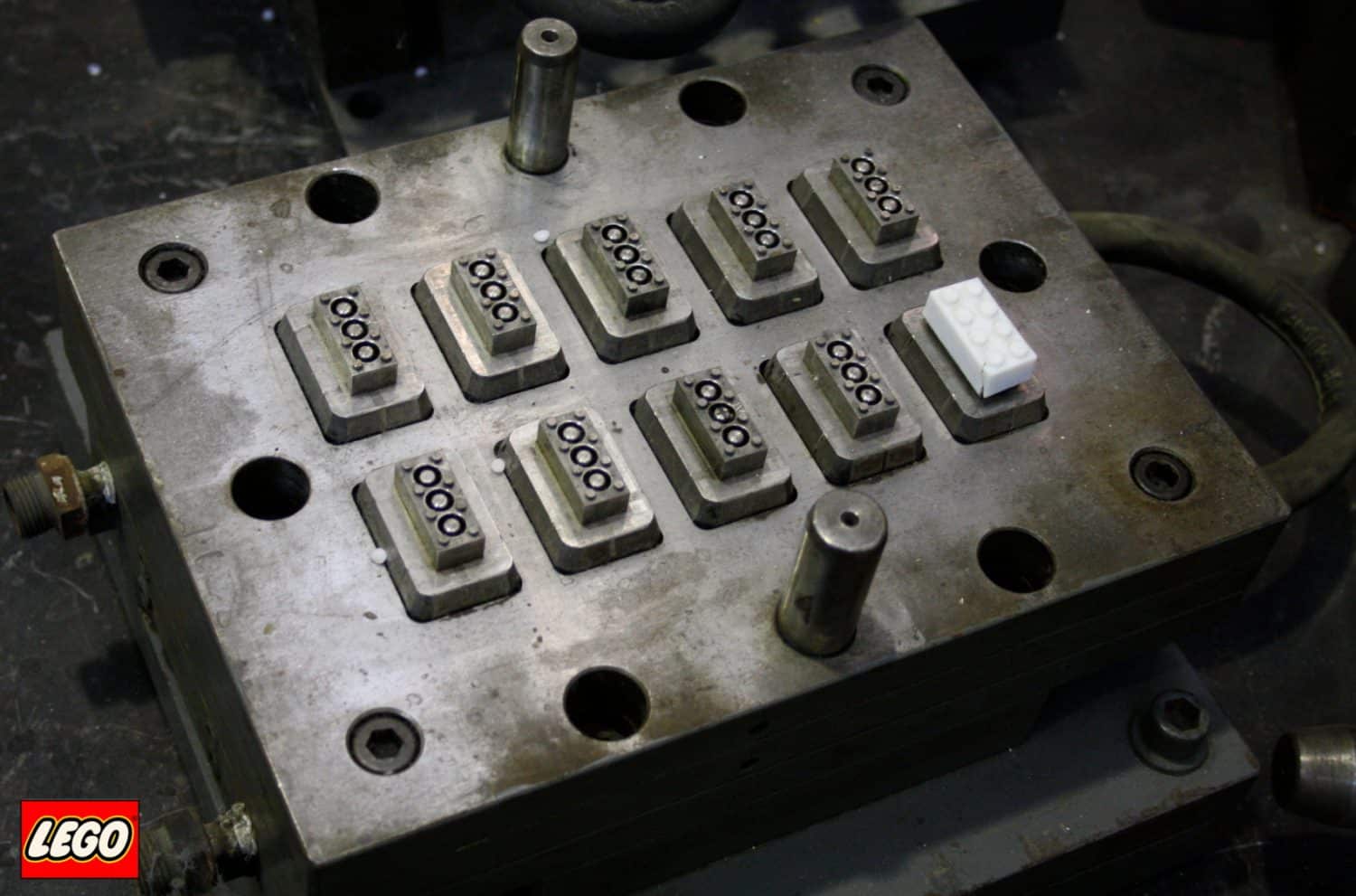
Craig Chamberlin2015-06-30 14:56:302015-07-31 11:41:46Injection Molding
https://www.precision-elec.com/wp-content/uploads/2015/06/injection-molding.jpg
991
1500
Craig Chamberlin
https://www.precision-elec.com/wp-content/uploads/2025/02/Precision-Electric-Logo-TEXT-ONLY-Color-NEW.png
Craig Chamberlin2015-06-30 14:56:302015-07-31 11:41:46Injection Molding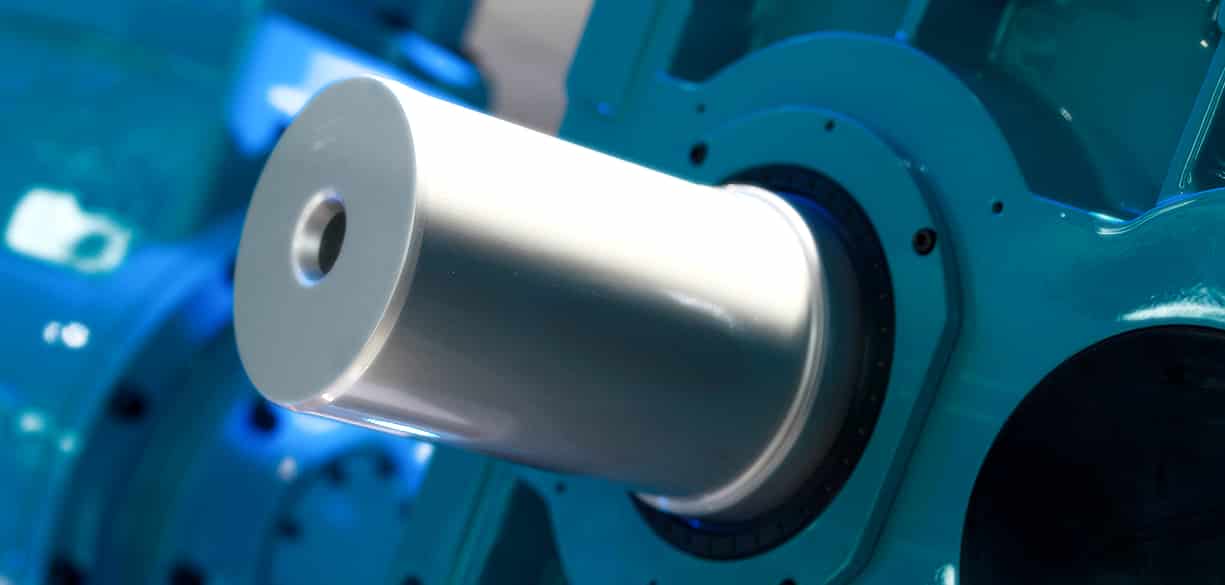 https://www.precision-elec.com/wp-content/uploads/2015/06/lenze-drive-repair.jpg
585
1225
Craig Chamberlin
https://www.precision-elec.com/wp-content/uploads/2025/02/Precision-Electric-Logo-TEXT-ONLY-Color-NEW.png
Craig Chamberlin2015-06-26 15:39:182015-07-31 11:41:46Lenze Drive Repair
https://www.precision-elec.com/wp-content/uploads/2015/06/lenze-drive-repair.jpg
585
1225
Craig Chamberlin
https://www.precision-elec.com/wp-content/uploads/2025/02/Precision-Electric-Logo-TEXT-ONLY-Color-NEW.png
Craig Chamberlin2015-06-26 15:39:182015-07-31 11:41:46Lenze Drive Repair https://www.precision-elec.com/wp-content/uploads/2015/06/harmonic-distortion.jpg
353
1183
Craig Chamberlin
https://www.precision-elec.com/wp-content/uploads/2025/02/Precision-Electric-Logo-TEXT-ONLY-Color-NEW.png
Craig Chamberlin2015-06-17 16:23:102015-07-31 11:41:46Harmonic Distortion
https://www.precision-elec.com/wp-content/uploads/2015/06/harmonic-distortion.jpg
353
1183
Craig Chamberlin
https://www.precision-elec.com/wp-content/uploads/2025/02/Precision-Electric-Logo-TEXT-ONLY-Color-NEW.png
Craig Chamberlin2015-06-17 16:23:102015-07-31 11:41:46Harmonic Distortion https://www.precision-elec.com/wp-content/uploads/2015/06/altivar-vfd.jpg
784
974
Craig Chamberlin
https://www.precision-elec.com/wp-content/uploads/2025/02/Precision-Electric-Logo-TEXT-ONLY-Color-NEW.png
Craig Chamberlin2015-06-12 14:33:322015-07-31 11:41:46Altivar VFD
https://www.precision-elec.com/wp-content/uploads/2015/06/altivar-vfd.jpg
784
974
Craig Chamberlin
https://www.precision-elec.com/wp-content/uploads/2025/02/Precision-Electric-Logo-TEXT-ONLY-Color-NEW.png
Craig Chamberlin2015-06-12 14:33:322015-07-31 11:41:46Altivar VFD https://www.precision-elec.com/wp-content/uploads/2015/06/eaton-cutler-hammer-drive-repair.jpg
1229
2048
Craig Chamberlin
https://www.precision-elec.com/wp-content/uploads/2025/02/Precision-Electric-Logo-TEXT-ONLY-Color-NEW.png
Craig Chamberlin2015-06-02 11:12:512015-07-31 11:41:47Eaton Cutler Hammer Drive Repair
https://www.precision-elec.com/wp-content/uploads/2015/06/eaton-cutler-hammer-drive-repair.jpg
1229
2048
Craig Chamberlin
https://www.precision-elec.com/wp-content/uploads/2025/02/Precision-Electric-Logo-TEXT-ONLY-Color-NEW.png
Craig Chamberlin2015-06-02 11:12:512015-07-31 11:41:47Eaton Cutler Hammer Drive Repair


