 https://www.precision-elec.com/wp-content/uploads/2016/05/hitachi-vfd-drives.jpg
328
1007
Craig Chamberlin
https://www.precision-elec.com/wp-content/uploads/2025/02/Precision-Electric-Logo-TEXT-ONLY-Color-NEW.png
Craig Chamberlin2016-05-30 10:56:562016-05-30 10:56:56Hitachi VFD Drives
https://www.precision-elec.com/wp-content/uploads/2016/05/hitachi-vfd-drives.jpg
328
1007
Craig Chamberlin
https://www.precision-elec.com/wp-content/uploads/2025/02/Precision-Electric-Logo-TEXT-ONLY-Color-NEW.png
Craig Chamberlin2016-05-30 10:56:562016-05-30 10:56:56Hitachi VFD Drives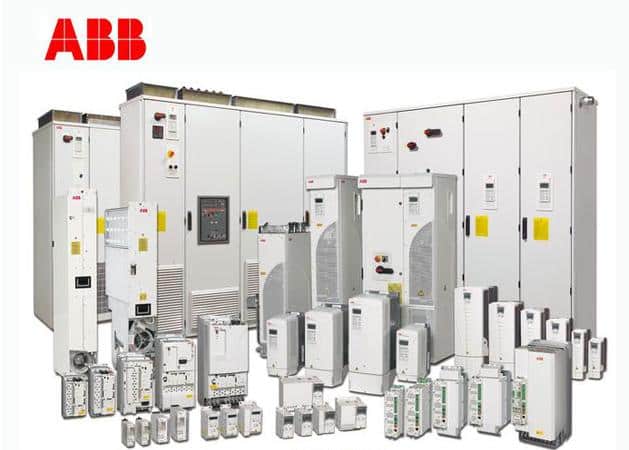 https://www.precision-elec.com/wp-content/uploads/2013/10/abb-acs800-4.jpg
450
629
Craig Chamberlin
https://www.precision-elec.com/wp-content/uploads/2025/02/Precision-Electric-Logo-TEXT-ONLY-Color-NEW.png
Craig Chamberlin2016-05-26 13:27:162018-04-20 17:14:13ABB VFD Drives Manual
https://www.precision-elec.com/wp-content/uploads/2013/10/abb-acs800-4.jpg
450
629
Craig Chamberlin
https://www.precision-elec.com/wp-content/uploads/2025/02/Precision-Electric-Logo-TEXT-ONLY-Color-NEW.png
Craig Chamberlin2016-05-26 13:27:162018-04-20 17:14:13ABB VFD Drives Manual https://www.precision-elec.com/wp-content/uploads/2016/05/siemens-vfd-troubleshooting-1.jpg
290
626
Craig Chamberlin
https://www.precision-elec.com/wp-content/uploads/2025/02/Precision-Electric-Logo-TEXT-ONLY-Color-NEW.png
Craig Chamberlin2016-05-10 12:22:562016-05-10 12:27:57Siemens VFD Troubleshooting
https://www.precision-elec.com/wp-content/uploads/2016/05/siemens-vfd-troubleshooting-1.jpg
290
626
Craig Chamberlin
https://www.precision-elec.com/wp-content/uploads/2025/02/Precision-Electric-Logo-TEXT-ONLY-Color-NEW.png
Craig Chamberlin2016-05-10 12:22:562016-05-10 12:27:57Siemens VFD Troubleshooting https://www.precision-elec.com/wp-content/uploads/2016/05/cutler-hammer-mcc.jpg
858
2048
Craig Chamberlin
https://www.precision-elec.com/wp-content/uploads/2025/02/Precision-Electric-Logo-TEXT-ONLY-Color-NEW.png
Craig Chamberlin2016-05-04 10:42:012016-05-04 10:56:20Cutler Hammer MCC
https://www.precision-elec.com/wp-content/uploads/2025/02/Precision-Electric-Logo-TEXT-ONLY-Color-NEW.png
261
1224
Craig Chamberlin
https://www.precision-elec.com/wp-content/uploads/2025/02/Precision-Electric-Logo-TEXT-ONLY-Color-NEW.png
Craig Chamberlin2016-05-04 10:20:022016-05-04 10:59:36Eaton Legacy Motor Control Centers
https://www.precision-elec.com/wp-content/uploads/2016/05/cutler-hammer-mcc.jpg
858
2048
Craig Chamberlin
https://www.precision-elec.com/wp-content/uploads/2025/02/Precision-Electric-Logo-TEXT-ONLY-Color-NEW.png
Craig Chamberlin2016-05-04 10:42:012016-05-04 10:56:20Cutler Hammer MCC
https://www.precision-elec.com/wp-content/uploads/2025/02/Precision-Electric-Logo-TEXT-ONLY-Color-NEW.png
261
1224
Craig Chamberlin
https://www.precision-elec.com/wp-content/uploads/2025/02/Precision-Electric-Logo-TEXT-ONLY-Color-NEW.png
Craig Chamberlin2016-05-04 10:20:022016-05-04 10:59:36Eaton Legacy Motor Control Centers


