Replacing Constant Speed With Variable Speed

In the past, applications operating at less than 300rpm, and rated from 500 kW to 5000 kW, have been controlledusing a medium-voltage constant speed synchronous motors. Commonapplications include crushers and various mills used inmetals, cement or mining.Replacing a constant speed with variable speed drive control brings substantial operating and maintenanceimprovements. Variable-speed drives provide soft starting, precise speed andtorque control and low stress on the electrical network.Soft starting lets the motor get up to speed gradually, therebyavoiding high inrush currents that can prevail when direct-onlinestarting is used. As such, the stress on the motor and allcomponents in the transmission train are much reduced. Thisavoids failure of key components while reducing maintenancecosts and prolonging motor and transmission life time.

ABB industrial drives feature the motor control platform, and direct torque control (DTC). DTC provides the highly accuratespeed and torque control often needed in slow speedapplications.With a power factor approaching unity, the variable-speeddrive has low reactive power consumption; thereby loweringvoltage variations on the supply network. The variable speed drive and motorcan be connected to weaker supply networks without theneed for power factor correction equipment. An advantage of using new synchronous motors with ABB industrial drives is that, for most cases, the existingfoundations can be re-used.A key benefit of variable-speed control is that the new motorhas fewer pole pairs and a smaller shaft height. This is becausea constant speed synchronous motor needs to be designed forits maximum speed. So a 2500 kW motor requiring 150 rpmhas 40 poles and typically a shaft height of 2000 mm. However,using variable-speed drive, the motor has between 8 to 24poles and a typical shaft height between 1250 to 1600 mm.This substantially lowers the motor costs and even when thedrive and transformer are considered, the investment will beless expensive than a 40-pole motor.

Benefits Of Replacing Constant Speed With Variable Speed:

  • Soft starting capability reduces stress on motor andtransmission train
  • Optimum speed according to process requirements
  • Lower maintenance costs and prolonged motor life
  • Low stress on the electrical network through unity powerfactor and low reactive power consumption
  • Choice of smaller traditional synchronous motor
  • No need to alter foundations thereby avoiding any loss ofproduction and costly civil works
  • Typically lower total cost than a new constant speedsynchronous motor

To learn more about replacing constant speed with variable speed, or forvariable speed drive repair and replacement quotes, contact Precision Electric, Inc.


VFD Machine Safety

Today, VFD machine safety technology is making the previously-complicated job of implementing a machine safety system much easier. Recent technical advances make safer operation less complex, while at the same time offering new potential for productivity. New developments in drive-based functional safety contribute to greater overall protection of people, machines and ecosystems. The aim is to help make VFD machine safety, and especially drive-based functional safety, easier for machine safety professionals.

In any industrial process it is critically important that when something goes wrong, the machinery is quickly and safely brought to a safe state, which usually means stopped. Once stopped it must not start unexpectedly. Depending on the application and its work cycles, machines may also need to operate at reduced speed during specific times. Any malfunction in machine control can result in hazardous situations leading to serious injury, or even death, with disastrous effects for the company, its people and its image. Ultimately, machine builders and system integrators have the responsibility for ensuring that any product or machine they supply is safe. It must be designed by following safety principles and must comply with relevant directives, standards and national laws. The machines end user has responsibility extending through the entire lifecycle of an industrial system. It is thus vitally important that safety planning is included from the very start of any machine design process. This way safety becomes a natural, functional part of the machinery and not an afterthought.

Drive-Based / VFD Machine Safety

VFD Machine SafetyDrive-based functional safety simplifies the task because drive safety functions are certified and integrated into the drive system. Safety is important in industrial applications involving motors, drives and programmable logic controllers. VFD machine safety is achieved by identifying and reducing risks to an acceptable level. Risk reduction is done by an inherently safe design and by applying risk-reducing protection measures.When done correctly, these measures can be flexible, reliable and easy-to-use. They also bring solid economic benefits such as increased productivity and uptime, without generating additional risks. The job of implementing a VFD machine safety system is today easier thanks to three main factors:

First, modern electronics enable safety functions to be directly integrated into a drives safety logic, so functional safety is a standard feature of the drive. Second, legislation has kept pace with these advancements, with new
standards that define the requirements and provides guidelines for implementing machinery safety. Third, engineering companies such as ABB have developed a wide range of safety devices and solutions that are easy to integrate in industrial applications for improved safety, uptime and functionality.

These three factors have enabled VFD machine safety solutions that can be more effective in preventing accidents, less costly to implement, easier to adapt and more reliable than previous hardwired electromechanical systems. Electromechanical safety systems are the result and can now be replaced with electronic safety functions. Built directly into the drives safety logic, the safety functions work seamlessly, side-by-side with the drives normal control functions.

VFD Machine SafetyDrives control movements such as motor speed and torque in industrial applications like conveyors and cranes. As levels, complexity and modularity of industrial automation increase, drive-based functional safety isfast becoming an important part of overall safety design for industrial processes. When sensing a hazardous situation a drive-based functional safety system can react in several ways. It might, for example, initiate an emergency stop based on user input. Or if it detects an out of control situation such as system overspeed, it can stop a process in a controlled and orderly way.

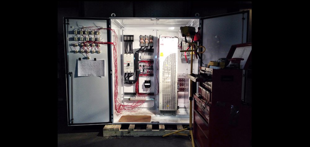
In larger systems with several drives, control of the overall safety system can be done using a safety PLC, which activates drive-based safety functions when required in the whole system. Functional safety can be easily achieved with safety devices that are, themselves, already certified to the most relevant functional safety standards. ABB drives include many certified safety functions either as standard, or are offered as options.ABB has put great emphasis on building safety functionality into its drives. ABB offers cost-efficient safety solutions with their drives, PLCs, and a full range of safety relays and contactors, emergency stop switches and othersafety devices. Depending on the needed machinery safety, ABB VFD machine safety solutions can range from one drive to an entire system of drives.Compared to the traditional safety solution, integrated drive-based functional safety includes the same functionality but it is simply built into the drive. The most basic functionality level is the STO circuit inside the drive whichcan safely disable the drives power stage, thus eliminating any need for a motor contactor.

ABBs offering of low voltage AC drives with STO as a standard feature are included on the following ABB products: ACS880, ACS580, ACS850, ACS355, ACQ810, ACSM1 and MicroFlex e150. The ACS800 drives have ABB STO (safe torque option) built-in as an optional feature.

Summary – VFD Machine Safety

The industrial environment is full of moving machine parts which can cause hazardous situations and lead to severe and often permanent injuries. The role of functional VFD machine safety is to protect people, property and ecosystems from often preventable accidents. It is therefore the ultimate responsibility of device suppliers, machine builders and system integrators to ensure that the products they deliver are safe.Safety for machines is achieved by complying with relevant safety directives and standards. In the EU, the EHSR which machine builders must comply with are defined in the Machinery Directive 2006/42/EC and the harmonized standards under this directive. For machine builders outside of EU the IEC/ISO versions of the EUs harmonized standards provide the necessary requirements and guidance.

Drives have been used for decades in many industrial applications. Where safety in automation systems once required many external add-on devices, the ever-increasing levels of automation employed in industry combined with the electronic technical capability of many modern drives and safety PLCs, mean drive systems now contribute greatly to the overall safety of a system. Today, new and improved safety solutions and standards enable VFD machine safety to become an integrated part of drive functionality. Drive-based functional safety means providing drive-based motion control that protects people, property and ecosystems. ABB drives offer many features that can help the safety designers achieve the required level of safety, in a cost-effective way.

For ABB VFD Repair or Replacement Quotes, Contact Precision Electric, Inc. To learn more about VFD machine safety or for more information about ABB drives, please visit the ABB Website.


Eaton Drive Repair

Variable speed drives have over the past decade allowed to become a cost efficient way to reduce power costs and increase system efficiency. Today manufacturers around the globe within a wide range of industries are finding more ways to apply drives to their rotating equipment.From past experience, smaller horsepower drives typically fail in eight years and are more often replaced rather than repaired.Larger horsepower drives last longer by virtue of repairs that often require replacement of circuit boards and other electrical components. After bearing the cost of two or three replacement boards in any one VFD drive, the user often realizes that the drive should have been junked sooner.

Eaton drive repair is common for Sullair service centers and manufacturers who use Eaton drives. Eaton drive repair is preferred by Sullair service centersand other Eaton drive usersbecause replacement is more expensive than repair.Most industrial manufacturing repair centers do not have the capabilities to offer Eaton drive repair, and that creates few alternativesfor Eaton drive users who are broke down.Eaton offers repair services for their drives with extensive lead times and most Eaton drive users cannot afford downtimewith extensive lead times.

Precision Electric saves Eaton drive users thousands of dollars by repairing failed Eaton drives. Precision Electric has also saved Eaton drive users in downtime by repairing Eaton drives in less time than it would have taken Eaton to replace a non-stock drive. Eaton drive repair is an asset to Sullair service centers and manufacturers who use Eaton drives.Precision Electric uses the most advanced testing equipment for all Eaton drive repair, and PrecisionElectric repair technicians have hundreds of years combined experience in testing and replacing Eaton drive components.

To learn more about Eaton drive repair or for Eaton drive repair and replacement quotes, contact Precision Electric.


ABB ACS250 VFD

ABB ACS250 VFDAlternating current VFD drive technology extends the motor speed range from zero to high above the rated speed of an electric motor, increasing the productivity of the driven process. When a low capacity is enough, the vfdreduces the machine speed and saves energy.

VFD equipmentall over the world save energy in applications for pumps, fans, conveyors and machines. The ABB ACS250 VFD drives provide flexible mounting alternatives and straightforward configuration and they are very easy to install and setup.The ABB ACS250 VFD is part of ABB’s complete micro drive range, which offers a solution for every application. The ABB ACS250 VFD can be used for simple to more complex machines. ABB ACS250 VFD enclosure sizes are available inIP20 series, in power ratings from single phase 110 – 120 Volt; for low power applications, such as pumps, fans, grinders, mixers and conveyors, through 600 Volt drives with more advanced features for general purpose applications.

The ABB ACS250 VFD is available in an IP66 enclosure in a full range of products for harsh environments. IP66 enclosed drives are ideal for wash-down applications and the offering covers all the voltages from 1-phase 110 Volt, to 3-phase 600 Volt.All ABB ACS250 VFD drives include a built-in Modbus-RTU serial communication, intuitive keypad control, and build-in macrostomake commissioning straightforward. IP66 enclosures are available with or without switch featuring a speed pot, FWD -0.REW and power isolator. In 500 – 600 Volt ABB ACS250 VFD advanced product types, the additional features include e.g. CAN open interface and built-in safe-torque-off (STO) function.

The ABB ACS250 VFD with IP66/NEMA 4X enclosure is designed for applications such as; screws, mixers, pumps, fans and conveyors, which are installed in harsh environments containingdust, moisture and cleaning chemicals. The Nema 4X drives design and ease of setup benet a broad range of industries.The Nema 4X drive was designed with bacteriaresistant materials, meeting stringenthygiene requirements, and the Nema 4X integratedkeypad provides straightforward drivecommissioning and maintenance inextreme environments. The drivessealed ABS enclosure and corrosionresistant heat sink are ideal for wash downapplications.

To learn more about the ABB ACS250 VFD, or for Repair and Replacement Quotes, contact Precision Electric, Inc.


Permanent Magnet Servo Motors

Permanent Magnet Servo Motors

Permanent magnet servo motors are also known as brushless servo motors and/or PM (permanent magnet) servo motors. Permanent magnet servo motors are used when an industrial application requires high performance and precise speed regulation. Permanent magnet servo motors are manufactured with a designated controller known as a servo drive or servo driver. Permanent magnet servo motors use position feedback to precisely regulate motor control by being paired with an encoder. Encoders measure a brushless servo motor’soutput shaft position which is compared to the command position. When the servo motor output shaft doesn’t match the demand signal, an error signal is sent to the servo motor controller; the controller adjusts accordingly and sends a signal back to the servo motor until the demand position is met. PM servo controllers (servo drive, driver, etc.) are never included in the base price of the servo motor. Servo motor systems can be expensive but the cost is justified with optimal manufacturing processes via precise speed regulation.

Servo motors output more torque than brushed direct current motors. Brushless servo motors aren’t as loud during operation than brushed direct current servo motors. The lifespan of brushless servo motors exceeds than that of a brushed direct current motor because there aren’t brushes or a commutator to maintain. The idea behind brushless servo motors was to be able to integrate control function of the servo motor with industrial electronic components and personal computers; and to precisely position machines in manufacturing processes. Some manufacturers use brushless servo motors in explosive and dirty environments because brushless servo motors are entirely closed and sealed to prevent dust or sparks to reach the servo motor parts.

Permanent Magnet Servo Motor Design Process

Permanent Magnet Servo MotorsThis process comprises threemain steps: Electromagnetic, structural and thermal designs. Electromagnetic design startswith magnetic circuit modeling and parameter optimization with a given set of designspecifications. A series of optimizations such as pole number, loading, current density,dimensional limits etc. have to be performed to find the optimum parameters of the motorbefore proceeding further. When a design is obtained that meets the technical spec, a quickmotor simulation and the influence of parameter variation must be carried out usingsimulation software such as SPEED (PC-BDC Manual, 2002). A detailed electromagneticfinite element analysis (FEA) either in 2D or 3D is the next step to verify that the designmeets the specified torque-speed characteristics and performance. After an electromagneticdesign is finalized, structural and thermal analyses (MotorCAD Manual 2004) have to becompleted. Structural analysis is not a necessity for design on low speed permanent magnet servo motors. If motor does not meet the structural or thermal tests, then theelectromagnetic design study should be repeated for a better design.

Permanent magnet servo motors are widely used in many industrial applications for theirsmall size, higher efficiency, noise-free operation, high speed range and better control. Thismakes quality of their torque an important issue in wide range of applications includingservo applications. For example, permanent magnet servo motors used in defense applications, robotics, servosystems, electric vehicles all require smooth torque operation.One of the most important issues in PM servo motors is the pulsating torque componentwhich is inherent in motor design. If a quality work is not completed during the designstage, this component can lead to mechanical vibrations, acoustic noise, shorter life anddrive system problems. In addition, if precautions are not taken, it can lead to seriouscontrol issues especially at low speeds. Minimization of the pulsating torque components isof great importance in the design of permanent magnet servo motors.In general, calculation of torque quality is a demanding task since the torque qualitycalculation does not only consider the torque density of the motor but also consider thepulsating torque component. Therefore, a mathematical approach about torque qualityshould include harmonic analysis of electric drive system rather than a simple sizing of the motor.

To learn more about permanent magnet servo motors or for servo motor repair and replacement quotes, contact Precision Electric, Inc.


Eaton VFD Repair

Eaton VFD Repair

Eaton VFD repair is an asset to Sullair service centers because Eaton VFD replacement isexpensive and longlead times for Eaton drives are a common problem. Sullair service centers often send their Eaton VFD repair to Precision Electric to increase production in the plant.Precision Electric service technicians have hundreds of years combined experience in bench testing components for Eaton VFD repair. Precision Electric uses the most advanced equipment for Eaton VFD repair, and Precision Electric replaces damaged components with better components than the Original Equipment Manufacturer uses.

Eaton VFD drives provide Sullair aircompressor applications with high speed output frequency up to 7200 Hz.Eaton variable frequency drivesautomatically identify motor parameters in sensorless vector mode as well as U/f mode, which keeps track of parameter changes over time. Eaton drivesallow for steady speed error, fast torque rise time, high immunity to resonance vibrations and high torque upon start up.

Minimizing Downtime Via Eaton VFD Repair

Eaton VFD RepairPrecision Electric repairs all Eaton Cutler Hammer variable frequency drives in house to ensure maximum efficiency and competitive repair costs. Since Precision Electric performs all Eaton VFD repair in house,customer downtime is greatly minimized sincethe equipment is not handled by anyone other than Precision Electric and the customer. Precision Electric also offers Eaton VFD repair in the field for equipment that needs troubleshooting on site.

Precision Electric offers 24/7 emergency repair services for Eaton drive users who do not have spare equipment on hand.Precision Electric recommends all manufacturers keep spare Eaton drives for crucial production lines, because keeping a spare Eaton drive willmaximize production when the primary Eaton drive fails. If a spare Eaton drive is not available for the manufacturer when the primary drive fails, production downtime usually exceeds the cost of a spare Eaton drive by far.

Precision Electric offers routine maintenance for Eaton VFD repair to provide manufacturing facilities with optimal production and to prevent emergency or rush repair services on Eaton equipment. Precision Electric routine maintenance consists of removing all parts of an Eaton drive, cleaning parts and all other components, replacement of damaged components, final testing of all electrical components, assembly of Eaton drive, final test of Eaton drive with electric motor, and safely packaging for delivery back to the customer. All repair work performed by Precision Electric includesa 12 month in service warranty. The in service warranty begins the exact day the Eaton drive is put into production, and ends 12 months later.

To learn more about Eaton VFD repair or for Eaton repair and replacement quotes, contact Precision Electric.


What Is A Variable Frequency Drive

What is a variable frequency drive? Variable frequencydrives are also known as variable speed drives, VFD’s, adjustable speed drives, and inverters.

Variable frequency drives are solid state motor control systems designed to control the speed of an AC (alternating current) electric motor. Variable frequency drives operate as load controls within AC electric motor applications; and variable frequency drives can reduce energy costsup to 50% by speed reduction on electric motorswhere the full speed (RPM) of the electric motor is not required.Variable frequency drives are used in AC servo systems, air compressors, conveyor systems, lathes, mills, plastic extrusion, slitter lines, food processing, waste water treatment systems, submersible pumps, HVAC fans and blowers, and many more electric motor applications.

Many manufacturers apply AC variable frequency drives to rotating equipment because variable frequency drives reduce amperage spikes upon start up of large electric motors.Choosing the right AC variable frequency drive for an application will benefit rotating equipment by providing less wear on the electric motors where applied.Adjusting the acceleration and deceleration time of electric motors can extend the lifespan of an electric motor. AC variable frequency drives provide the ability to control the frequency of starting and stopping of an AC electric motor.This ability allowsan AC electric motor to only operate when needed for the equipment it’s rotating, and electric motors have a longer lifespan if they are not continuously operating when they don’t need to be.

Approximately one third of the world’s electrical energy is supplied by electric motors in fixed-speed centrifugal pump, fan, and air compressor applications. These fixed-speed applications hardly ever require the full load speed (RPM) of the electric motor in which they’re operating. By installing AC variable frequency drives to these applications, electric motor speeds are reduced, and power costs can be reduced by 50% or more. Technology has allowed cost and physical size reduction of AC variable frequency drives, and has improved performance through advances in semiconductor switching devices, simulation, control techniques, and control hardware and software.

Power Savings: What Is A Variable Frequency Drive

The majority of AC variable frequency drives in the market today contain electronic circuitry that converts 60 Hertz Line power into direct current. The variable frequency drive converts this line power into a pulsed output voltage that duplicates varying alternating current to a desired frequency (speed).A properly applied AC variable frequency drive when paired with an AC electric motor will significantly reduce operating costs for manufacturers. This is particularly true for variable torque loads such as fans, blowers, and pumps.Blowers are often used with dampers to control air flow; these dampers may operate either manually or automatically. When dampers are closed, 50% of the electric motor current will drop to approximately 60% of full load nameplate current. By utilizing an AC variable frequency drive in blower applications, the current draw of the motor will be reduced 30% for every 10% drop in speed. The same electric motor operating froman AC variable frequency drive at 50% speed, will draw approximately 20% of the full load current.

Example Application:

A 10 horsepower AC electric motor, rated 90% efficient, operating across the line without an AC variable frequency drive, with the dampers operating between 50 70%, for 2000 hours per year will require 11,996 KWH. If the KWH charge is $.08 per KWH, the cost to run this motor will be: $1,248.00 annually.The same 10 horsepower electric motor operating from an AC variable frequency drive, between 50 70% speed for 2000 hours per year will require 4,676 KWH. Operating cost at the same KWH rate will be: $432.00 per year. This represents a savings of $816.00 per year and should be enough to pay for the AC variable frequency drives investment and installation costs, within the first 12 months of operation.If any electric motor application operates more hours than in the above example, and/orthe KWH charge is higher, the savings will quickly compound.The energy saved on a utility bill from using a variable frequencydrive is often significant enough to pay for the variable speed frequencywithin a couple of months from installation date.Increasing and/or decreasing the start up time on an AC current electric motor via a variable frequencydrive can add years to the motor’s overall lifespan. Using a variable frequencydrive can also improve efficiency on production demands. Variable frequencydrives provide the ability to control the frequency of starting and stopping an AC electric motor.This ability provides a means by which an AC electric motor is only operating when needed. AC electric motors have a longer lifespan if they are not continuously operating when they do not need to be.

Types Of Drives: What Is A Variable Frequency Drive

Volts Per Hertz drives are the most common type of variable frequency drive and areknown as a V/Hz drives, or volts by hertz drives. V/Hz variable frequency drives are used inapplications such as fans, pumps, air compressors, and other related applications wherehigh starting torque is not required. V/Hz variable frequencydrive applications typically do not require full torque when the AC motor is operating at less than the base speed (RPM) of the electric motor. V/Hz variable frequencydrives are the most inexpensive type of variable frequencydrive. V/Hz variable frequencydrives do not provide full motor torque at low RPM.

Open-Loop vector drives are also known as “sensorless vector” variable frequencydrives. Open loop vector drives adapted the name “sensorless vector” because they do not use an external encoder for speed feedback to the motor.Open loop vector drives are used in applications where high starting torque and full torque at low speed (RPM) is required. Open-Loop vector drives operating a motor a zero RPM should not be used on crane or hoist applications. Most open-loop vector drives are used on CNC machines, mixers, mills, lathes, and other applications where high starting torque or full torque at low RPM is needed.Open loop vector drives are usually more expensive than a V/Hz variable speed drives.

Closed-Loop vector drives are used in applications where precise speed control (0.01%) is needed, or in applications where extensive programming is needed. Closed-Loop vector drives use an encoder on the motor to provide constant shaft position indication to the drive’s microprocessor. The encoder feedback allows the drive microprocessor to constantly control torque no matter how many RPM the motor is operating at. Closed-Loop vector drives are used to provide the motor to operate at full torque even at zero RPM. Closed-Loop vector drives are commonly used on hoist and crane applications because crane and hoist motors must produce full torque prior to it’s brake being released, or the load will drop and it will not be able to stop.

To learn more about variable frequency drives or for repair and replacement quotes, contact Precision Electric, Inc.

Yaskawa VFD Drives

Yaskawa VFD drives are designed to minimize harmful demand for input harmonic distortion. Yaskawa VFD drives up to25 HP are available with optional 3% or 5% equivalent line impedance DC Bus Reactors.At 30 HP and above, Yaskawa VFD drives include 3% impedance as standard. Some Yaskawa VFD drives include a dual diode bridgerectifier which can be configured to accept 12-pulse(delta-delta and delta-wye secondary) transformerinput. Yaskawa VFD drives can also be factory configured with an integral18-pulse transformer. These packages are typicallyused to meet the most strict harmonic requirementsat both drive input terminals and the point of commoncoupling.

Yaskawa VFD drives are factory-programmed and ready torun. An LCD interface enhances ease of use with itsmultiple language support and parameter copy feature thatallows duplication of settings between drives. In addition,a portable USB Copy Unit (1000 series only) providesa very convenient method of desktop configurationtransportable to the factory floor.All Yaskawa VFD drives have a split cover for easy access to thepower and control terminals. The power terminal compartmenteasily accommodates bend radius for cable connections. Controlwires are connected to a detachable terminal board for ease ofinstallation and maintenance.

Detachable cooling fans are easy to replace and on/off fan controlcan extend operating life. Accumulated operation time and coolingfan run time are recorded and can be displayed for preventivemaintenance programs.Start-up and configuration are simplified by the intuitiveprogramming menu and start-up procedure.DriveWizard Industrial is a PC-based support tool for drivecommissioning and maintenance. It provides a way to operatethe drive, change parameters, upload and download parameters,monitor and graph parameters, provide status and troubleshootingdata, and utilize a host of additional features with built-in helpmenus.

Yaskawa VFD Drives Product Overview

Yaskawa VFD DrivesThe Yaskawa A1000 is a multi-purpose VFD drive deliveringup to 1000 horsepower, and provides Yaskawas highest levelof vector performance including precise controlof both induction and permanent magnet motors.The Yaskawa A1000 VFD drive is a full featured drive, providing outstanding quality,performance, flexibility, and environmental friendliness through 1000HP.Enjoy network communications, feedback, and expandable I/O to controlanything from simple fans and pumps to complex machines. For newinstallations or retrofits, the Yaskawa A1000 VFD drive provides a single robust solution,regardless of the application.

The Yaskawa G7 VFD drive is the ultimate performancesolution with increased speed and torque response to provide servo-likeperformance from an induction motor. The Yaskawa G7 VFD drive has theworlds first 480V 3-level inverter architecture that eliminates orminimizes the installation problems associated with IGBT switching andprotects the entire motor-drive system. The Yaskawa G7 VFD drive performance makes it the ideal drive for high performancespeed, torque, or position control applications. Several control modesare provided in the G7. In open loop vector mode, the latest flux observeralgorithms extend speed range and provide maximum starting torque.In closed loop vector mode, 0.01% speed regulation and 1000:1 controlrange can be achieved. Zero-servo capability provides position controlat zero speed.

The Yaskawa P1000 VFD drive is the next generation in Industrial Fan and Pump control,designed for those applications that are variable torque. Simplicity,intuitiveness, and user friendliness were the key factors in the Yaskawa P1000 VFD drive design. The Yaskawa P1000 VFD drive includes a powerful set of pre programmedfan/pump application macros allowing for quick and easycommissioning. With its advanced motor control algorithm alongwith the next generation IGBT technology, motor noise and drivepackaging is reduced. The P1000 supports a wide range of network andcontrol options providing for the most cost effective solution.

The Yaskawa J1000 VFD drive is a general purpose AC drive; its PWM designprovides low motor noise and high starting torque, with a heavy dutycurrent overload rating of 150% for 60 seconds and a normal dutycurrent overload rating of 120% for 60 seconds. Volts per hertz control makesthe Yaskawa J1000 VFD drive suitable for most general applications. The J1000 is feature packed,low cost and compact. The digital operator includes a 5-digitLED status display. TheYaskawaJ1000 VFD drive has five multi-function digital inputs,one multi-function analog input, one multi-function digital output,and one multi-function analog output. An optional RS-422/485Modbus RTU serial communication port is available. An ideal choicewhenever low cost and small size are required.

The Yaskawa V1000 VFD drive is a high performance line of AC micro drives withlow motor noise and high starting torque. It provides two controlmethods; Volts per hertz,and open loop current vector control for precise speedregulation and higher torque at lower speeds. The Yaskawa V1000 VFD driveis intendedfor either heavy duty applications or normal duty applications. The Yaskawa V1000 VFD drive is the perfect choice wherever highperformance in a small size is required.

To learn more about Yaskawa VFD drives, please visit the Yaskawa Website or contact Precision Electric.


dc variable speed drives, abb 500 horsepower control cabinet

DC Variable Speed Drives

The first electric motors were designed and built for operation from direct current power.The following should be considered when choosing DC variable speed drives for production:

  • Wide speed range
  • Good speed regulation
  • Compact size and light weight
  • Ease of control
  • Low maintenance
  • Low cost

dc variable speed drive, 500 horsepower ABB variable speed drive

In order to determine if DC variable speed drives have the capability to provide the above characteristics, the DC drive has to be analyzed as two elements that make up the package. These two elements are the electric motor and the control.General purpose DC motors used on nearly all packaged drives have a very simple performance characteristic; the motor shaft turns at a speed directly proportional to the voltage applied to the armature.The Armature amperage of a DC motor is almost directly proportional to output torque regardless of speed. This characteristic indicates that a small fixed amount of current is required to turn the motor even when there is no output torque. This is due to the friction of the bearings, electrical losses in the motor materials and load imposed by the air in the motor winding.

DC motor speed is primarily determined by the applied armature voltage and DC motor torque is controlled by armature current.Understanding these concepts of DC motors provides the key to understanding the performance of DC variable speed drives. DC variable speed drives use a control module. This control module rectifies alternating current power and converts it to direct current for DC motor control. The control module also controls the DC output voltage and amperage in response to various control and feedback signals. The feedback signals then regulate the DC motor performance via speed, and torque.

The regulating function of DC variable speed drives provide an electronic circuit that monitors a number of inputs and sums these signals to produce an error signal. This error signal is processed and transformed into precisely timed pulses that are applied to the gates of the Silicon Controlled Rectifier(SCR) in the power bridge, thereby regulating the power output to the DC motor.In order to control DC motor speed accurately it is necessary to provide DC variable speed drives with a feedback signal related to motor speed. The standard method of doing this in a simple control is by monitoring the armature voltage and feeding it back into the regulator for comparison with the input set point signal.When armature voltage becomes high, relative to the set point, established by the speed potentiometer setting, an error is detected and the output voltage from the power bridge is reduced to lower the motor’s speed back to the “set point”. Similarly when the armature voltage drops an error of opposite polarity is sensed and the control output voltage is automatically increased in an attempt to re-establish the desired speed. The “Armature Voltage Feedback System” which is standard in most packaged drives is generally called a “Voltage Regulated Drive”.

A second and more accurate method of obtaining the motor speed feedback information is called “Tachometer Feedback”. In this case the speed feedback signal is obtained from a motor mounted tachometer. The output of this tachometer is directly related to the speed of the motor. Using Tachometer Feedback gives a DC variable speed drive improved regulation characteristics. When “tach feedback” is used the drive is referred to as a “Speed Regulated Drive”. Most DC drives are capable of being modified to accept tachometer signals for operation in the tachometer feedback mode.In some newer high performance “digital drives” the feedback can come from a motor mounted encoder that feeds back voltage pulses at a rate related to motor speed. These (counts) are processed digitally being compared to the “set point” and error signals are produced to regulate the armature voltage and speed.

In addition to the normal external adjustment such as the speed pot, there are anumber of common internal adjustments that are used on simple small analog type DC variable speed drives.The following is a description of the functions that these individual adjustments serve and theirtypical use.

Adjustments Of DC Variable Speed Drives & Motors

DC Variable Speed DrivesIn most cases when DC variable speed drives are initially installed, the speed potentiometer can be turneddown to its lowest point and the output voltage from the drive will go to zero, then the motor will stop.There are many situations where this is not desirable, because there are some machinesthat need to be kept running at a minimum speed and accelerated up to operating speed asnecessary. There is also a possibility that an operator may use the speed potentiometer tostop the motor to work on the machine. This can be a dangerous situation since the motor hasonly been brought to a stop by zeroing the input signal voltage. A more desirable situation iswhen the motor is stopped by opening the circuit to the motor or power to the control usingthe on/off switch. By adjusting the minimum speed up to some point where the motorcontinues to run even with the speed potentiometer set to its lowest point, the operator mustshut the control off to stop the motor. This adds safety into the system. The typicalminimum speed adjustment is from 0 to 30% of motor base speed.

The maximum speed adjustment sets the maximum speed attainable either by raising the inputsignal to its maximum point or turning the potentiometer to the maximum point. On a typicalDC motor the rated speed of the motor might 1750 RPM but the control might be capable ofrunning it up to 1850 or 1900 RPM. In some cases it’s desirable to limit the motor (and machinespeed) to something less than would be available at this maximum setting. The maximumadjustment allows this to be done. By turning the internal potentiometer to a lower point themaximum output voltage from the control is limited. This limits the maximum speed availablefrom the motor.

Digital DC variable speed drives are capable of constantly monitoring the DC motor current. The current drawn by the armature of theDC motor is related to the torque that is required by the load. Since this monitoring and controlis available an adjustment is provided in the drive that limits the output current to amaximum value.This function can be used to set a threshold point that will cause the motor to stall ratherthan putting out an excessive amount of torque. This capability gives the motor/drive combination the ability to prevent damage that might otherwise occur if higher values oftorque were available. This is handy on machines that might become jammed or otherwisestalled. It can also be used where the drive is operating a device such as the center winderwhere the important thing becomes torque rather than the speed. In this case the current limitis set and the speed goes up or down to hold the tension 0f the material being wound. Thecurrent limit is normally factory set at 150% of the motor’s rated current. This allows the motorto produce enough torque to start and accelerate the load and yet will not let the current(and torque) exceed 150% of its rated value when running. The range of adjustment istypically from 0 to 200% of the motor rated current.

IR compensation is a method used to adjust for the droop in a motor’s speed due to armature resistance. As mentioned previously, IR compensation is positive feedback that causes thecontrol output voltage to rise slightly with increasing output current. This will help stabilize the motor’s speedfrom a no load to full load condition. If the motor happens to be driving a load where the torque isconstant or nearly so, then this adjustment is usually unnecessary. However, if the motor is driving a loadwith a widely fluctuating torque requirement, and speed regulation is critical, then IR compensationcan be adjusted to stabilize the speed from the light load to full load condition. One caution isthat when IR compensation is adjusted too high it results in an increasing speed characteristic. This meansthat as the load is applied the motor is actually going to be forced to run faster. When thishappens it increases the voltage and current to the motor which in turn increases the motor speed further. If thisadjustment is set too high an unstable “hunting” or oscillating condition occurs that is undesirable.

The Acceleration Time adjustment performs the function that is indicated by its name. It willextend or shorten the amount of time for the motor to go from zero speed up to the set speed. It alsoregulates the time it takes to change speeds from one setting (say 50%) to another setting(perhaps 100%). So this setting has the ability to moderate the acceleration rate on the DC variable frequency drive.If an acceleration time that’s too rapid is called for, “accelerationtime” will be overridden by the current limit. Acceleration will only occur at a rate that is allowed by theamount of current the control passes through to the motor. On most small DC variable speed drives, the acceleration time is not linear. What this means is that a change of 50 RPM may occur more rapidly when the motor is at low speed than it does when the motor is approaching the set pointspeed. This is important to know but usually not critical on simple applications where these drives are used.This is an adjustment that allows loads to be slowed over an extended period of time. Forexample, if power is removed from the motor and the load stops in 3 seconds, then the deceleration timeadjustment would allow an increased time and “power down” the load over a period of 4, 5, 6 ormore seconds.

To learn more about DC variable speed drives or for DC variable speed drive repair and replacement quotes, contact Precision Electric, Inc.


Information References:

http://www.fincor.net


types of vfd drives

Types Of VFD Drives

There are 3 general types of VFD drives:

Each of these types of VFD drives can be divided into different variations. Every type of VFD drive system runs an electric motor and a speed control unit. VFD drive technology in today’s manufacturing processes mainly consist of solid state electronic components in a single control system. Older VFD drive systems use mechanical moving parts that in short periods of time, result in equipment failure due to worn parts from constant motion.

Eddy Current Systems – Types Of VFD Drives

types of vfd drivesThese types of VFD drives use an eddy current electric motor system. An eddy current type of VFD drive consists of a fixed speed motor and an eddy current clutch. The clutch contains a fixed speed rotor and a variable speed rotor separated by a small air gap. A direct current in a field coil produces a magnetic field that determines thetorquetransmitted from the input to the output rotor. The controller provides closed loop speed regulation by varying the clutch current, allowing the clutch to transmit enough torque to operate at the desired speed. Speed feedback is provided by an integral AC tachometer.

Eddy current VFD drives are less efficient than all other types of variable frequency drives.Nearly all eddy current motor drive systems are obsolete today. Eddy Current motor drives were designed and manufactured decades ago and there are very few manufacturing facilities across the globe that still use them in production. When an Eddy Current motor drive system fails, it’s usually too expensive to repair and impossible to replace. When an Eddy Current motor drive reaches the end of its life cycle and can no longer be repaired, manufacturers retrofit the Eddy Current Drive Systems with an AC Induction Motor and an AC VFD Drive system.

DC Systems – Types Of VFD Drives

types of vfd drivesThese types of VFD drives use DC (direct current) electric motors. DC (direct current) motors have a rotating armature winding (winding in which a voltage is induced) but non-rotating armature magnetic field, and a static field winding (winding that produces the main magnetic flux) or permanent magnet. Different connections of the field and armature winding provide different inherent speed/torque regulation characteristics. The speed of a DC motor can be controlled by changing the voltage applied to the armature or by changing the field current. The introduction of variable resistance in the armature circuit or field circuit allowed speed control. Modern DC motors are often controlled bypower electronicssystems called DC VFD drives.

There are different types of DC VFD drives, but the most common are known as DC Motor Speed Control Systems.The speed of a DC motor is directly proportional to armature voltage and inversely proportional to motor flux; either armature voltage or field current can be used to control the motor speed. DC Motors have become expensive and today most DC motor speed control systems are retrofitted with an AC induction motor and AC VFD drive. AC VFD drives are less expensive than DC Drive systems, are more available, and are more energy efficient than DC VFD Drive systems.

AC Systems – Types Of VFD Drives

types of vfd drivesThese types of VFD drives use AC (alternating current) electric motors. AC VFD drives are also known as Variable Frequency Drives, VSDs (variable speed drives), AFDs (adjustable speed drives), inverters, and micro drives. AC variable frequency drives are used in many applications such as AC Servo Systems, Air Compressors, Conveyor Systems, Lathes, Mills, Food Processing production lines, Waste Water treatment systems, Submersible Pumps, HVAC fans and blowers, and many more applications.Approximately one third of the world’s electrical energy is supplied by electric motors in fixed-speed centrifugal pump, fan, and air compressor applications. This proves thatsignificant energy efficiency improvement opportunities are available if older DC motor speed control systems and eddy current drive systems are retrofitted with AC variable frequency drive systems.Most industrial manufacturers replace their eddy current and DC variable frequency drive systems with AC variable frequency drive systems.

Technology has reduced the physical size and cost of AC variable frequency drives, and has improved performance through advances in semiconductor switching devices, simulation, control techniques, and control hardware and software.Manufacturers capitalize on AC VFD drive technology to save money on power consumption, increase quality control, decrease production downtime, and improve overall efficiency on production lines.


Information References:


ac variable frequency drives - bottling line

AC Variable Frequency Drives

ac variable frequency drives - bottling lineAC variable frequency drives are also known as VFDs, VSDs (variable speed drives), AFDs (adjustable speed drives), inverters, and micro drives. AC variable frequency drives are used in AC Servo Systems, Air Compressors, Conveyor Systems, Lathes, Mills, Plastic Extrusion, Slitter Lines, Food Processing, Waste Water Treatment Systems, Submersible Pumps, HVAC Fans and Blowers, and many more applications.

Many manufacturers apply AC variable frequency drives to rotating equipment because variable frequency drives reduce amperage spikes upon start up of large electric motors.Choosing the right AC variable frequency drive for an application will benefit rotating equipment by providing less wear on the electric motors where applied.Adjusting the acceleration and deceleration time of electric motors can extend an electric motor’s lifespan. AC variable frequency drives provide the ability to control the frequency of starting and stopping of an AC electric motor.This ability provides a means by which an AC electric motor is only operating when needed for the equipment it’s rotating, and electric motors have a longer lifespan if they are not continuously operating when they don’t need to be.

Approximately one third of the world’s electrical energy is supplied by electric motors in fixed-speed centrifugal pump, fan, and air compressor applications. These fixed-speed applications hardly ever require the full load speed (RPM) of the electric motor in which they’re operating. By installing AC variable frequency drives to these applications, the motor speeds are reduced, and power costs can be reduced by 50% or more. Technology has reduced cost and physical size of AC variable frequency drives, and has improved performance through advances in semiconductor switching devices, simulation, control techniques, and control hardware and software.

Power Savings Via AC Variable Frequency Drives

ac variable frequency drives - bottling lineAC variable frequency drives are used to reduce power savings in food processing, plastic extrusion, waste water treatment, and many other applications.AC variable frequency drives operate as load controls within applications that may accomplish up to 50% reduction in energy costs. Electric motors will turn at a rate proportional to the frequency of the alternating current (AC) applied to it.

The majority of AC variable frequency drives in the market today contain electronic circuitry that converts 60 Hertz Line power into direct current. The variable frequency drive converts this line power into a pulsed output voltage that duplicates varying alternating current to a desired frequency (speed).A properly applied AC variable frequency drive when paired with an AC electric motor, will significantly reduce operating costs. This is particularly true for variable torque loads such asFans,Blowers, andPumps.Blowers, for example, are often used with dampers to control air flow. These dampers may operate either manually or automatically. When dampers are closed, 50% of the electric motor current will drop to approximately 60% of Full Load nameplate current. By utilizing an AC variable frequency drive in this application, current draw in the motor will be reduced 30% for every 10% drop in speed. The same electric motor operating froman AC variable frequency drive at 50% speed, will draw approximately 20% of the full load current.

Example Application: AC Variable Frequency Drives

ac variable frequency drives - bottling lineA 10 horsepower AC electric motor, rated 90% efficient, operating across the line without an AC variable frequency drive, with the dampers operating between 50 70%, for 2000 hours per year will require 11,996 KWH. If the KWH charge is $.08 per KWH, the cost to run this motor will be: $1,248.00 annually.The same 10 horsepower electric motor operating from an AC variable frequency drive, between 50 70% speed for 2000 hours per year will require 4,676 KWH. Operating cost at the same KWH rate will be: $432.00 per year. This represents a savings of $816.00 per year and should be enough to pay for the AC variable frequency drives investment and installation costs, within the first 12 months of operation.If any electric motor application operates more hours than in the above example, and/orthe KWH charge is higher, the savings will quickly compound.

Manufacturers across the globe capitalize on AC variable frequency drives to save money on power consumption, increase quality control, decrease production downtime, and improve overall efficiency. To learn more about AC variable frequency drives or for repair and replacement quotes, contact Precision Electric, Inc.


energy saving vfd

Energy Saving VFD

Over the past decade, energy saving VFD drives have allowed to become a cost efficient way to reduce power costs and increase system production efficiency. Approximately one third of the world’s electrical energy is supplied by electric motors in fixed-speed centrifugal pump, fan, and air compressor applications. These fixed-speed applications don’t always require the full load speed (RPM) of the electric motor in which they’re operating. By installing an energy saving VFD drive to these applications, the motor speed is reduced, and power costs can be reduced by 50% or more.This energy savings is often significant enough to pay for energy saving VFD drives within a few months.

Energy Saving VFD – Applications

Energy saving VFD drives are used in many applications such as swimming pool pumps, air compressors, conveyor belts, lathes, mills, food processing, plastic extrusion, waste water treatment pumps, HVAC fans and blowers, and many more. Energy saving VFD drivesare used in manufacturing to increase or decrease the acceleration and deceleration times on alternating current (AC) motors.

Adjusting the acceleration and deceleration time on electric motors can extend the motor’s lifespan, and can also improve efficiency on production demands. Energy saving VFD drives can also provide the ability to control the frequency of starting and stopping an AC motor.This ability provides a means by which an AC electric motor is only operating when needed for the equipment it’s rotating, and electric motors have a longer lifespan if they are not continuously operating when they don’t need to be.

energy saving vfdUtilizing energy saving VFD drives can greatly increase power savings in food processing, plastic extrusion, waste water treatment, and many other manufacturing sites. Many manufacturers apply energy saving VFD drives to their rotating equipment because they reduce amperage spikes upon start up of large electric motors.Choosing the right energy saving VFD drive for an application will increase power savings on utility bills, increase production flow, and will benefit rotating equipment by providing less wear on the electric motors where applied.

The use of energy saving VFD drives on variable torque loads for the purpose of gaining energy savings is a common goal. VFD drives operate as load controls within applications that may accomplish up to 50% reduction in energy costs.In general, an electric motor will turn at a rate proportional to the frequency of the alternating current (AC) applied to it.The majority of VFD drives in the market today contain electronic circuitry that converts 60 Hertz Line power into direct current. The VFD converts this line power into a pulsed output voltage that duplicates varying alternating current to a desired frequency (speed).A properly applied energy saving VFD Drive will significantly reduce operating costs. This is particularly true for variable torque loads such as:

  • Fans
  • Blowers
  • Pumps

Blowers, for example, are often used with dampers to control air flow. These dampers may be operated either manually or automatically. When dampers are closed, 50% of the electric motor current will drop to approximately 60% of Full Load nameplate current. By utilizing an energy saving VFD drive in this application, current draw in the motor will be reduced 30% for every 10% drop in speed. The same electric motor operating froman energy saving VFD drive, at 50% speed, will draw approximately 20% of the full load current.

Example Application:

A 10 horsepower AC electric motor, rated 90% efficient, operating across the line (without an energy saving VFD) with the dampers operating between 50 70%, for 2000 hours per year will require 11,996 KWH. If your KWH charge is $.08 per KWH, the cost to run this motor will be: $1,248.00 annually.

The same 10 horsepower electric motor operating from an energy saving VFD Drive, between 50 70% speed for 2000 hours per year will require 4,676 KWH. Operating cost at the same KWH rate will be: $432.00 per year. This represents a savings of $816.00 per year and should be enough to pay for the energy saving VFD investment and installation costs in the first 12 months of operation.

If any electric motor application operates more hours than in the above example, and/orthe KWH charge is higher, the savings will quickly compound.

Energy Saving VFD – Repair Versus Replacement

In our ever growing world of technology, energy saving VFD drives have over the past decade allowed to become a cost efficient way to reduce power costs and increase system efficiency. Today manufacturers around the globe within a wide range of industries are finding more ways to apply energy saving VFD drives to their rotating equipment.From past experience, smaller horsepower VFD drives typically fail in eight years and are more often replaced rather than repaired.

Larger horsepower VFD drives last longer by virtue of repairs that often require replacement of circuit boards and other electrical components. After bearing the cost of two or three replacement boards in any one VFD drive, the user often realizes that the drive should have been junked sooner.