Sensorless (Open Loop) Vector Control, Speed Control (V / Hz), Torque Control (Constant), Torque Control (Variable)
Analog Input(s)
1 Input (0 - 10 VDC), 1 Input (4 - 20 mA)
Analog Output(s)
2 Outputs (0 - 10 VDC / 2 - 10 VDC / 4 - 20 mA)
Control Input(s)
5 Inputs (NPN)
Control Output(s)
1 Output (Relay), 2 Outputs (NPN)
Integrated EPM Module:
Yes
Integrated Keypad:
Yes
Integrated Fwd / Rev Switch:
No
Integrated Speed Pot:
No
Integrated Disconnect:
No
Integrated Brake Chopper:
No
Integrated Communications:
Modbus RTU (RS-485)
Learn More
You can hover your mouse over highlighted product specs to learn more.
Description
Estimated reading time: 14 minutes
Introduction: Understanding the Lenze AC Tech SCF Variable Frequency Drives VFDs
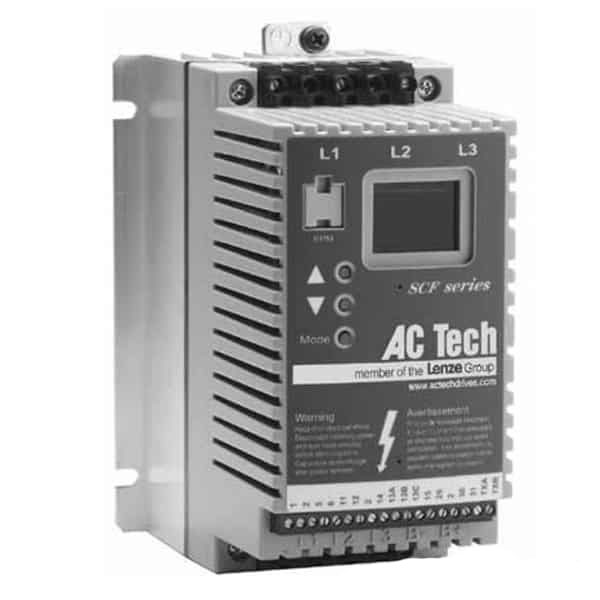
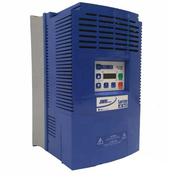
In the world of industrial automation, precise and reliable AC Tech motor control is fundamental to operational efficiency and equipment longevity. The Lenze AC Tech SCF Variable Frequency Drives (VFDs) stand out as a compact, yet powerful solution designed to meet these demands. These drives, also known as AC inverter drives, function by converting incoming fixed-frequency AC power into a variable-frequency, variable-voltage output, thereby enabling precise control over the speed, torque, and acceleration of standard induction motors. Consequently, this control allows for process optimization and significant energy savings across a wide range of applications, from simple conveyors to more complex machine automation.
Lenze AC Tech SCF VFD: Power & Voltage Specs
Despite their sub-micro footprint, Lenze VFD drives in the SCF series are remarkably versatile and robust. According to specifications published by Carotron, the product line covers an extensive power range from 0.25 HP to 30 HP (0.18 to 22 kW) and supports various input voltages, including 120V, 240V, 480V, and 590V AC. Furthermore, many models are designed to accept either single-phase or three-phase input power, which offers immense flexibility for integration into different electrical systems. This adaptability makes the SCF variable speed drive a suitable choice for both new system designs and retrofitting existing machinery, ensuring it can be deployed in diverse industrial environments without requiring major electrical infrastructure changes.
The core functionality of the Lenze SCF series VFD is its Volts-per-Hertz (V/f) control method, a straightforward yet effective way to manage motor speed. In other words, the drive maintains a constant ratio between voltage and frequency to ensure stable motor torque throughout its operational range. This VFD motor controller technology is particularly effective for variable-torque applications like fans and pumps, where even a small reduction in motor speed can lead to substantial energy savings, as highlighted by industry experts at Borderstates. By precisely matching motor output to the actual load requirement, these drives not only reduce power consumption but also minimize mechanical wear and tear, ultimately extending the service life of the entire system. You can find more information in the official AC Tech VFD manual or on the Lenze website.
Critical Safety Protocols for VFD Installation and Maintenance
Adhering to strict safety protocols is non-negotiable when installing or servicing any AC inverter drive, and the Lenze SCF series VFD is no exception. Before beginning any work, technicians must follow established lockout/tagout (LOTO) procedures to ensure the equipment is completely de-energized. This involves disconnecting and locking the main power source to prevent accidental reactivation. According to the official AC Tech VFD manual, only qualified personnel who are familiar with the drive and associated machinery should perform these tasks. Consequently, compliance with standards from OSHA and NFPA 70E is mandatory to prevent electrical shock, arc flash, and other serious hazards.
Verifying Zero Energy in Lenze SCF VFDs
A critical danger specific to any Variable Frequency Drive (VFD) is the stored electrical energy within its internal DC bus capacitors. Even after power has been removed, these components can retain a hazardous voltage for several minutes. For this reason, technicians must always verify a zero-energy state by using a properly rated voltmeter to test the DC bus terminals before touching any internal components. The service guidelines detailed by Lenze explicitly warn against immediate contact after power-down. Failing to wait for the capacitors to fully discharge is one of the most dangerous mistakes one can make during VFD motor controller maintenance.
The Lenze AC Tech SCF series is a cornerstone of reliable AC motor control. These variable frequency drives (VFDs) offer precise speed adjustments for various industrial applications.
Furthermore, using the correct Personal Protective Equipment (PPE) is essential for safeguarding against electrical risks. This includes, at a minimum, safety glasses, voltage-rated gloves, and arc-rated clothing as determined by an arc flash risk assessment. All wiring practices must conform strictly to the National Electrical Code (NEC) and any applicable local codes to ensure a safe and reliable installation. Properly grounding the Lenze AC Tech SCF variable frequency drives VFDs is not just a suggestion but a requirement for both safety and preventing electromagnetic interference, as noted in resources from distributors like SCF Series AC Drives. Always consult the manufacturer's documentation for specific guidelines on grounding, fusing, and wiring.
Key Features and Specifications of the Lenze SCF Series VFD
The Lenze SCF series VFD stands out in the crowded micro-drive market by offering a robust feature set within a compact, sub-micro footprint. This AC inverter drive is designed for versatility, covering a wide power range from 0.25 to 30 HP (0.18 to 22 kW) to suit various motor control applications. According to Lenze SCF Inverters, these drives support multiple voltage inputs, including 120/240 VAC single-phase, 208/240 VAC, 400/480 VAC, and 590 VDC. Consequently, this flexibility makes the SCF a suitable choice for both new system designs and retrofitting existing machinery, ensuring broad compatibility as detailed in the AC Tech VFD manual.
Lenze AC Tech SCF VFD I/O Capabilities
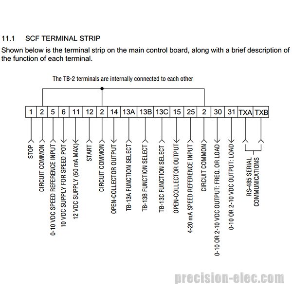
A significant advantage of the SCF variable speed drive is its comprehensive I/O and communication capabilities, which are often optional on competing micro-drives. The drive features 18 isolated control terminals, providing extensive options for digital and analog control without the need for additional expansion modules. For instance, it includes multiple programmable digital inputs, analog inputs (0-10VDC / 4-20mA), and relay outputs for enhanced process control. Furthermore, as noted by Carotron SCF Series Drives, every SCF model comes standard with an RS485 serial port supporting the Modbus RTU protocol, which greatly simplifies integration into networked industrial control systems. This built-in connectivity provides a cost-effective solution for remote monitoring and control.
Simplified Lenze drive programming and maintenance are core to the SCF's design, primarily through its innovative Electronic Programmable Module (EPM) system. The EPM is a small memory chip that stores all the drive's configuration parameters. This allows for rapid programming of multiple drives by simply copying the EPM, a feature invaluable for OEMs and large facilities. In other words, if a drive ever needs replacement, an operator can simply remove the EPM from the old unit and plug it into the new one, completely transferring the settings in seconds. As highlighted by Carotron, this minimizes downtime and eliminates the need for manual reprogramming, streamlining the maintenance process significantly.
Proper Installation and Wiring of Your AC Tech Motor Control
Proper installation is a critical first step for ensuring the longevity and safe operation of your AC Tech motor control. Before beginning, it is imperative to perform a full lockout/tagout procedure on the incoming power source to comply with OSHA and NFPA 70E standards. Consequently, a thorough review of the manufacturer's guidelines is essential; for instance, the official AC Tech VFD manual provides detailed diagrams and specifications crucial for a successful setup. Always verify that the VFD's voltage and horsepower ratings match the motor and the application's requirements to prevent equipment damage.
Following manufacturer-specified safety protocols, such as wearing appropriate PPE, is essential when performing maintenance on any AC Tech motor control like the Lenze SCF series.
Begin by mounting the SCF variable speed drive in a clean, dry, and vibration-free location, ensuring it is vertically oriented to promote natural convection cooling. It is important to maintain adequate clearance around the unit as specified in the manual to prevent overheating. As noted by Lenze SCF Inverters, most Lenze SCF series VFD units come with an IP20 rating, meaning they are intended for installation inside a protective enclosure, such as a NEMA 1 or NEMA 12 panel, to shield them from dust and moisture. Furthermore, consider the ambient operating temperature, as excessive heat can significantly shorten the drive's lifespan.
Wiring Lenze SCF VFDs: Grounding & Protection
Next, focus on the power and motor wiring, using the appropriate wire gauge as mandated by the National Electrical Code (NEC) for the drive's full-load amperage. A solid, low-impedance ground connection is not optional; in fact, it is critical for both safety and noise suppression. For overcurrent protection, it is highly recommended to use the specified fuses. For instance, the installation manual recommends using UL Class CC fast-acting fuses to protect the drive's input, as detailed in documentation from Valinonline. Be sure to keep power wiring physically separated from control wiring to minimize electrical noise interference.
Finally, complete the control wiring according to your application's schematic. The Lenze VFD drives feature 18 isolated terminals for control I/O, which provides excellent noise immunity for signals like start/stop commands, external speed references (0-10VDC or 4-20mA), and fault outputs. According to SCF Series Stan, this robust I/O allows for versatile integration into various control systems. Double-check all connections at both the drive and the control devices before reapplying power to the system to ensure everything functions as intended.
A Step-by-step Guide to Lenze Drive Programming and Commissioning
Properly commissioning your Lenze SCF series VFD is the final and most critical step to ensure optimal performance and longevity for your motor control system. Fortunately, the process is designed to be straightforward, relying on a simple keypad interface and a logical parameter structure. Before beginning, it is essential to have the motor's nameplate data readily available and to have thoroughly reviewed the official AC Tech VFD manual. This initial preparation ensures that all settings accurately reflect the connected load, preventing potential faults or damage during startup. Consequently, a methodical approach is the best way to guarantee a smooth and successful commissioning process from the very start.
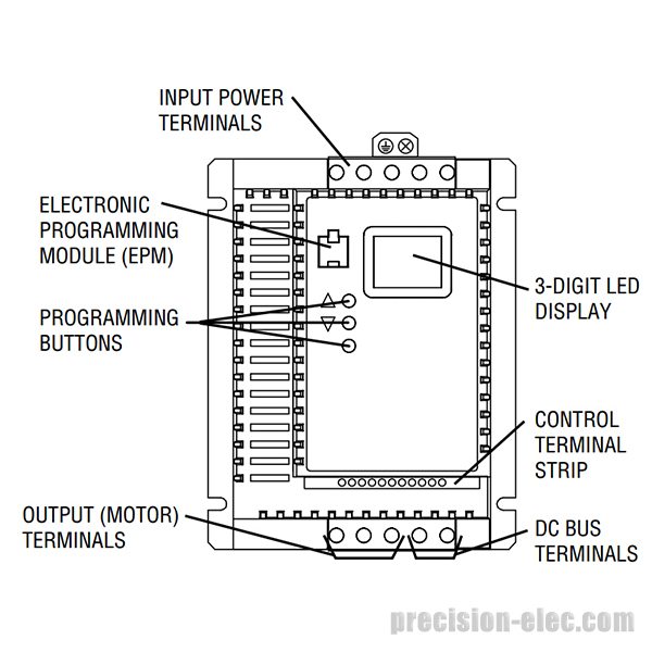
Initial Power-up and Keypad Navigation
After completing all wiring and safety checks, you can apply power to the VFD. The drive's LED display will illuminate, typically showing its status or the last set frequency. Navigation is handled through a set of intuitive keys: UP, DOWN, SHIFT/ENTER, and MODE/RESET. According to the AC Tech SCF Drives Manual installation guide, these keys allow you to scroll through different parameter groups, select a specific parameter to view or edit, and save the new value. For instance, you will press the MODE key to enter the parameter menu, use the UP/DOWN keys to find the desired parameter number, and press SHIFT/ENTER to view and change its setting. Holding the SHIFT/ENTER key saves the new value to the drive’s memory.
Basic Setup for Lenze SCF VFD Drives
The Lenze AC Tech SCF series VFD combines a user-friendly interface with a robust feature set in a compact footprint, making it ideal for a wide range of motor control applications.
Essential Parameters for Basic AC Tech Motor Control
While the Lenze SCF drive has an extensive parameter list, only a few are needed for most basic applications. Initially, you must configure the motor data, including motor voltage, full-load amps (FLA), and base frequency (typically 60 Hz in North America). In addition, setting the acceleration (P03) and deceleration (P04) times is crucial for controlling how quickly the motor ramps up to speed and comes to a stop, protecting both the motor and the driven machinery from mechanical shock. Other important settings outlined by sources like SCF Series Variable Speed Drives include minimum/maximum frequency and selecting the start/stop control method (e.g., keypad, terminal strip, or serial communications).
Utilizing the EPM for Efficient Lenze Drive Programming
A standout feature of the SCF series is the Electronic Programmable Module (EPM), a small memory chip that stores all drive parameters. As noted by SCF Series AC Drives, this innovation is a significant time-saver for commissioning multiple drives with identical settings. Instead of programming each VFD individually, a technician can program one EPM and then copy its configuration to other drives simply by plugging it in. This process takes only seconds. It is important to remember that the drive will not operate without the EPM installed, as it contains all the essential configuration data. Therefore, as documented in the manual, you must never insert or remove the EPM while the drive is powered, as this can cause damage to the module or the VFD motor controller itself. This feature not only speeds up commissioning but also simplifies drive replacement in the field, minimizing downtime significantly.
Troubleshooting Common Fault Codes on Lenze VFD Drives
Effectively diagnosing issues with Lenze AC Tech SCF variable frequency drives VFDs is crucial for minimizing operational downtime. These drives feature a comprehensive set of fault codes designed to alert technicians to specific problems within the motor control system. When a fault occurs, the drive's display will flash a code, which provides a starting point for any diagnostic work. While consulting the official AC Tech VFD manual is essential for a complete list, understanding the most common codes can significantly speed up the troubleshooting process. Consequently, before attempting any diagnostics, always follow proper lockout/tagout procedures to de-energize the equipment safely.
An F02 (Overcurrent) or F03 (Overload) fault is one of the most frequent issues, indicating that the motor has drawn excessive current. This can result from several causes, such as a sudden mechanical jam in the driven load, an improperly configured acceleration ramp, or incorrect motor data programmed into the VFD. For instance, if the acceleration time is too short for a high-inertia load, the VFD may trip on overcurrent. To resolve this, first investigate the mechanical system for any binding or blockages. In addition, you should verify that the motor's nameplate voltage, amperage, and frequency settings in the drive parameters match the connected motor exactly.
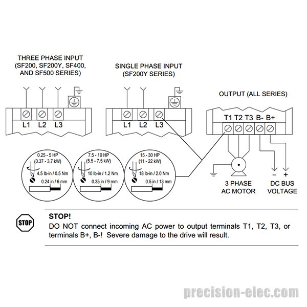
Proper wiring is crucial for the safe and efficient operation of your AC Tech motor control. This diagram highlights the key connections for a successful installation.
Overvoltage (F04) and undervoltage (F05) faults point to problems with the incoming power supply or regenerative energy. An overvoltage condition often happens during rapid deceleration, where the motor acts as a generator and sends excess voltage back to the AC inverter drive. The primary solution is to increase the deceleration time, allowing the energy to dissipate more slowly. For applications requiring fast stops, installing an external dynamic braking resistor is the most effective solution, as noted by Lenze SCF Inverters. Conversely, an undervoltage fault typically signifies a sag or interruption in the main AC supply, requiring a thorough inspection of input power wiring and terminal connections for any loose or faulty contacts.
An F13 fault code indicates a problem with the Electronic Programmable Module (EPM), the chip that stores all the drive's parameter settings. This fault can occur if the EPM is not securely seated, has been damaged, or is incompatible with the drive. The drive will not operate without a correctly programmed EPM, a feature that allows for rapid replacement of a failed drive by simply transferring the EPM. According to documentation from SCF Series AC Drives, this system simplifies maintenance significantly. If you encounter an F13 fault, carefully power down the unit, re-seat the EPM, and inspect it for any visible damage before powering the drive back on. If the fault persists, the EPM itself may require replacement or reprogramming.
Preventive Maintenance for Your SCF Variable Speed Drive
To ensure the longevity and reliable operation of your SCF variable speed drive, a consistent preventive maintenance schedule is essential. Before performing any service, it is critical to follow all safety protocols, including proper lockout/tagout procedures, to de-energize the equipment completely. Consequently, this simple step prevents unexpected motor starts and protects personnel from electrical hazards. For detailed safety guidelines specific to the Lenze AC Tech SCF Variable Frequency Drives VFDs, always consult the official documentation, such as the comprehensive guide provided by AC Tech SCF Drives Manual.
Routine physical inspections form the foundation of effective VFD maintenance. Specifically, you should ensure the drive is free from dust, moisture, and corrosive contaminants that can lead to short circuits or overheating. Check that the cooling fan is operational and that the heatsink fins are clear, allowing for proper heat dissipation, a key design feature detailed by Lenze SCF Inverters. In addition, periodically verify that all terminal connections for power and control wiring are secure, as vibrations during operation can cause them to loosen over time.
Beyond visual checks, it is wise to perform periodic electrical assessments. For instance, you can measure and log input and output voltage and current to identify any significant deviations from the baseline. Furthermore, reviewing the drive's fault history can reveal intermittent issues that need attention. According to documentation from sources like SCF Series AC Drives, regularly backing up drive parameters is a best practice. It is also important to inspect components like DC bus capacitors, especially after a long period of storage, as noted in the AC Tech VFD manual, to ensure they can still hold a proper charge.
Conclusion: Maximizing the Performance of Your Lenze VFD Drives
In conclusion, the effective implementation of Lenze AC Tech SCF variable frequency drives VFDs hinges on a comprehensive understanding of their installation, programming, and maintenance requirements. Throughout this guide, we have detailed the critical steps from initial wiring in compliance with NEC standards to advanced parameter adjustments. By following these established procedures, technicians and engineers can ensure not only the safe operation of the AC Tech motor control but also its optimal performance and longevity. Consequently, this diligence translates directly into enhanced system reliability and efficiency.
Maximizing the return on your investment in an SCF variable speed drive involves more than just initial setup; it requires an ongoing commitment to preventive maintenance and diligent troubleshooting. For instance, regularly inspecting connections and monitoring for fault codes can prevent costly downtime. For specific guidance, always refer to official documentation, such as the detailed manual provided by AC Tech SCF Drives Manual. This proactive approach ensures the VFD motor controller continues to deliver the significant energy savings and precise motor control that, according to VFD Energy Savings, are primary benefits of VFD technology.
Ultimately, the Lenze SCF series VFD is a robust and versatile tool for a wide range of industrial applications. Its feature set, as highlighted by resources from both Lenze SCF Inverters and distributors like SCF Series Drives, provides a powerful solution for modern motor control challenges. By leveraging the knowledge presented here—from safety protocols to programming nuances—you are well-equipped to manage the entire lifecycle of your Lenze VFD drives, ensuring they remain a valuable asset in your operations for years to come. Therefore, continuous learning and adherence to best practices are the final keys to unlocking their full potential.
Read The Full Lenze Ac Tech SCF Variable Frequency Drives Vfds Research:
Sensorless (Open Loop) Vector Control, Speed Control (V / Hz), Torque Control (Constant), Torque Control (Variable)
Analog Input(s)
1 Input (0 - 10 VDC), 1 Input (4 - 20 mA)
Analog Output(s)
2 Outputs (0 - 10 VDC / 2 - 10 VDC / 4 - 20 mA)
Control Input(s)
5 Inputs (NPN)
Control Output(s)
1 Output (Relay), 2 Outputs (NPN)
Integrated EPM Module:
Yes
Integrated Keypad:
Yes
Integrated Fwd / Rev Switch:
No
Integrated Speed Pot:
No
Integrated Disconnect:
No
Integrated Brake Chopper:
No
Integrated Communications:
Modbus RTU (RS-485)
Learn More
You can hover your mouse over highlighted product specs to learn more.
Description
Estimated reading time: 14 minutes
Introduction: Understanding the Lenze AC Tech SCF Variable Frequency Drives VFDs
In the world of industrial automation, precise and reliable AC Tech motor control is fundamental to operational efficiency and equipment longevity. The Lenze AC Tech SCF Variable Frequency Drives (VFDs) stand out as a compact, yet powerful solution designed to meet these demands. These drives, also known as AC inverter drives, function by converting incoming fixed-frequency AC power into a variable-frequency, variable-voltage output, thereby enabling precise control over the speed, torque, and acceleration of standard induction motors. Consequently, this control allows for process optimization and significant energy savings across a wide range of applications, from simple conveyors to more complex machine automation.
Lenze AC Tech SCF VFD: Power & Voltage Specs
Despite their sub-micro footprint, Lenze VFD drives in the SCF series are remarkably versatile and robust. According to specifications published by Carotron, the product line covers an extensive power range from 0.25 HP to 30 HP (0.18 to 22 kW) and supports various input voltages, including 120V, 240V, 480V, and 590V AC. Furthermore, many models are designed to accept either single-phase or three-phase input power, which offers immense flexibility for integration into different electrical systems. This adaptability makes the SCF variable speed drive a suitable choice for both new system designs and retrofitting existing machinery, ensuring it can be deployed in diverse industrial environments without requiring major electrical infrastructure changes.
The core functionality of the Lenze SCF series VFD is its Volts-per-Hertz (V/f) control method, a straightforward yet effective way to manage motor speed. In other words, the drive maintains a constant ratio between voltage and frequency to ensure stable motor torque throughout its operational range. This VFD motor controller technology is particularly effective for variable-torque applications like fans and pumps, where even a small reduction in motor speed can lead to substantial energy savings, as highlighted by industry experts at Borderstates. By precisely matching motor output to the actual load requirement, these drives not only reduce power consumption but also minimize mechanical wear and tear, ultimately extending the service life of the entire system. You can find more information in the official AC Tech VFD manual or on the Lenze website.
Critical Safety Protocols for VFD Installation and Maintenance
Adhering to strict safety protocols is non-negotiable when installing or servicing any AC inverter drive, and the Lenze SCF series VFD is no exception. Before beginning any work, technicians must follow established lockout/tagout (LOTO) procedures to ensure the equipment is completely de-energized. This involves disconnecting and locking the main power source to prevent accidental reactivation. According to the official AC Tech VFD manual, only qualified personnel who are familiar with the drive and associated machinery should perform these tasks. Consequently, compliance with standards from OSHA and NFPA 70E is mandatory to prevent electrical shock, arc flash, and other serious hazards.
Verifying Zero Energy in Lenze SCF VFDs
A critical danger specific to any Variable Frequency Drive (VFD) is the stored electrical energy within its internal DC bus capacitors. Even after power has been removed, these components can retain a hazardous voltage for several minutes. For this reason, technicians must always verify a zero-energy state by using a properly rated voltmeter to test the DC bus terminals before touching any internal components. The service guidelines detailed by Lenze explicitly warn against immediate contact after power-down. Failing to wait for the capacitors to fully discharge is one of the most dangerous mistakes one can make during VFD motor controller maintenance.
The Lenze AC Tech SCF series is a cornerstone of reliable AC motor control. These variable frequency drives (VFDs) offer precise speed adjustments for various industrial applications.
Furthermore, using the correct Personal Protective Equipment (PPE) is essential for safeguarding against electrical risks. This includes, at a minimum, safety glasses, voltage-rated gloves, and arc-rated clothing as determined by an arc flash risk assessment. All wiring practices must conform strictly to the National Electrical Code (NEC) and any applicable local codes to ensure a safe and reliable installation. Properly grounding the Lenze AC Tech SCF variable frequency drives VFDs is not just a suggestion but a requirement for both safety and preventing electromagnetic interference, as noted in resources from distributors like SCF Series AC Drives. Always consult the manufacturer's documentation for specific guidelines on grounding, fusing, and wiring.
Key Features and Specifications of the Lenze SCF Series VFD
The Lenze SCF series VFD stands out in the crowded micro-drive market by offering a robust feature set within a compact, sub-micro footprint. This AC inverter drive is designed for versatility, covering a wide power range from 0.25 to 30 HP (0.18 to 22 kW) to suit various motor control applications. According to Lenze SCF Inverters, these drives support multiple voltage inputs, including 120/240 VAC single-phase, 208/240 VAC, 400/480 VAC, and 590 VDC. Consequently, this flexibility makes the SCF a suitable choice for both new system designs and retrofitting existing machinery, ensuring broad compatibility as detailed in the AC Tech VFD manual.
Lenze AC Tech SCF VFD I/O Capabilities
A significant advantage of the SCF variable speed drive is its comprehensive I/O and communication capabilities, which are often optional on competing micro-drives. The drive features 18 isolated control terminals, providing extensive options for digital and analog control without the need for additional expansion modules. For instance, it includes multiple programmable digital inputs, analog inputs (0-10VDC / 4-20mA), and relay outputs for enhanced process control. Furthermore, as noted by Carotron SCF Series Drives, every SCF model comes standard with an RS485 serial port supporting the Modbus RTU protocol, which greatly simplifies integration into networked industrial control systems. This built-in connectivity provides a cost-effective solution for remote monitoring and control.
Simplified Lenze drive programming and maintenance are core to the SCF's design, primarily through its innovative Electronic Programmable Module (EPM) system. The EPM is a small memory chip that stores all the drive's configuration parameters. This allows for rapid programming of multiple drives by simply copying the EPM, a feature invaluable for OEMs and large facilities. In other words, if a drive ever needs replacement, an operator can simply remove the EPM from the old unit and plug it into the new one, completely transferring the settings in seconds. As highlighted by Carotron, this minimizes downtime and eliminates the need for manual reprogramming, streamlining the maintenance process significantly.
Proper Installation and Wiring of Your AC Tech Motor Control
Proper installation is a critical first step for ensuring the longevity and safe operation of your AC Tech motor control. Before beginning, it is imperative to perform a full lockout/tagout procedure on the incoming power source to comply with OSHA and NFPA 70E standards. Consequently, a thorough review of the manufacturer's guidelines is essential; for instance, the official AC Tech VFD manual provides detailed diagrams and specifications crucial for a successful setup. Always verify that the VFD's voltage and horsepower ratings match the motor and the application's requirements to prevent equipment damage.
Following manufacturer-specified safety protocols, such as wearing appropriate PPE, is essential when performing maintenance on any AC Tech motor control like the Lenze SCF series.
Begin by mounting the SCF variable speed drive in a clean, dry, and vibration-free location, ensuring it is vertically oriented to promote natural convection cooling. It is important to maintain adequate clearance around the unit as specified in the manual to prevent overheating. As noted by Lenze SCF Inverters, most Lenze SCF series VFD units come with an IP20 rating, meaning they are intended for installation inside a protective enclosure, such as a NEMA 1 or NEMA 12 panel, to shield them from dust and moisture. Furthermore, consider the ambient operating temperature, as excessive heat can significantly shorten the drive's lifespan.
Wiring Lenze SCF VFDs: Grounding & Protection
Next, focus on the power and motor wiring, using the appropriate wire gauge as mandated by the National Electrical Code (NEC) for the drive's full-load amperage. A solid, low-impedance ground connection is not optional; in fact, it is critical for both safety and noise suppression. For overcurrent protection, it is highly recommended to use the specified fuses. For instance, the installation manual recommends using UL Class CC fast-acting fuses to protect the drive's input, as detailed in documentation from Valinonline. Be sure to keep power wiring physically separated from control wiring to minimize electrical noise interference.
Finally, complete the control wiring according to your application's schematic. The Lenze VFD drives feature 18 isolated terminals for control I/O, which provides excellent noise immunity for signals like start/stop commands, external speed references (0-10VDC or 4-20mA), and fault outputs. According to SCF Series Stan, this robust I/O allows for versatile integration into various control systems. Double-check all connections at both the drive and the control devices before reapplying power to the system to ensure everything functions as intended.
A Step-by-step Guide to Lenze Drive Programming and Commissioning
Properly commissioning your Lenze SCF series VFD is the final and most critical step to ensure optimal performance and longevity for your motor control system. Fortunately, the process is designed to be straightforward, relying on a simple keypad interface and a logical parameter structure. Before beginning, it is essential to have the motor's nameplate data readily available and to have thoroughly reviewed the official AC Tech VFD manual. This initial preparation ensures that all settings accurately reflect the connected load, preventing potential faults or damage during startup. Consequently, a methodical approach is the best way to guarantee a smooth and successful commissioning process from the very start.
Initial Power-up and Keypad Navigation
After completing all wiring and safety checks, you can apply power to the VFD. The drive's LED display will illuminate, typically showing its status or the last set frequency. Navigation is handled through a set of intuitive keys: UP, DOWN, SHIFT/ENTER, and MODE/RESET. According to the AC Tech SCF Drives Manual installation guide, these keys allow you to scroll through different parameter groups, select a specific parameter to view or edit, and save the new value. For instance, you will press the MODE key to enter the parameter menu, use the UP/DOWN keys to find the desired parameter number, and press SHIFT/ENTER to view and change its setting. Holding the SHIFT/ENTER key saves the new value to the drive’s memory.
Basic Setup for Lenze SCF VFD Drives
The Lenze AC Tech SCF series VFD combines a user-friendly interface with a robust feature set in a compact footprint, making it ideal for a wide range of motor control applications.
Essential Parameters for Basic AC Tech Motor Control
While the Lenze SCF drive has an extensive parameter list, only a few are needed for most basic applications. Initially, you must configure the motor data, including motor voltage, full-load amps (FLA), and base frequency (typically 60 Hz in North America). In addition, setting the acceleration (P03) and deceleration (P04) times is crucial for controlling how quickly the motor ramps up to speed and comes to a stop, protecting both the motor and the driven machinery from mechanical shock. Other important settings outlined by sources like SCF Series Variable Speed Drives include minimum/maximum frequency and selecting the start/stop control method (e.g., keypad, terminal strip, or serial communications).
Utilizing the EPM for Efficient Lenze Drive Programming
A standout feature of the SCF series is the Electronic Programmable Module (EPM), a small memory chip that stores all drive parameters. As noted by SCF Series AC Drives, this innovation is a significant time-saver for commissioning multiple drives with identical settings. Instead of programming each VFD individually, a technician can program one EPM and then copy its configuration to other drives simply by plugging it in. This process takes only seconds. It is important to remember that the drive will not operate without the EPM installed, as it contains all the essential configuration data. Therefore, as documented in the manual, you must never insert or remove the EPM while the drive is powered, as this can cause damage to the module or the VFD motor controller itself. This feature not only speeds up commissioning but also simplifies drive replacement in the field, minimizing downtime significantly.
Troubleshooting Common Fault Codes on Lenze VFD Drives
Effectively diagnosing issues with Lenze AC Tech SCF variable frequency drives VFDs is crucial for minimizing operational downtime. These drives feature a comprehensive set of fault codes designed to alert technicians to specific problems within the motor control system. When a fault occurs, the drive's display will flash a code, which provides a starting point for any diagnostic work. While consulting the official AC Tech VFD manual is essential for a complete list, understanding the most common codes can significantly speed up the troubleshooting process. Consequently, before attempting any diagnostics, always follow proper lockout/tagout procedures to de-energize the equipment safely.
An F02 (Overcurrent) or F03 (Overload) fault is one of the most frequent issues, indicating that the motor has drawn excessive current. This can result from several causes, such as a sudden mechanical jam in the driven load, an improperly configured acceleration ramp, or incorrect motor data programmed into the VFD. For instance, if the acceleration time is too short for a high-inertia load, the VFD may trip on overcurrent. To resolve this, first investigate the mechanical system for any binding or blockages. In addition, you should verify that the motor's nameplate voltage, amperage, and frequency settings in the drive parameters match the connected motor exactly.
Proper wiring is crucial for the safe and efficient operation of your AC Tech motor control. This diagram highlights the key connections for a successful installation.
Overvoltage (F04) and undervoltage (F05) faults point to problems with the incoming power supply or regenerative energy. An overvoltage condition often happens during rapid deceleration, where the motor acts as a generator and sends excess voltage back to the AC inverter drive. The primary solution is to increase the deceleration time, allowing the energy to dissipate more slowly. For applications requiring fast stops, installing an external dynamic braking resistor is the most effective solution, as noted by Lenze SCF Inverters. Conversely, an undervoltage fault typically signifies a sag or interruption in the main AC supply, requiring a thorough inspection of input power wiring and terminal connections for any loose or faulty contacts.
An F13 fault code indicates a problem with the Electronic Programmable Module (EPM), the chip that stores all the drive's parameter settings. This fault can occur if the EPM is not securely seated, has been damaged, or is incompatible with the drive. The drive will not operate without a correctly programmed EPM, a feature that allows for rapid replacement of a failed drive by simply transferring the EPM. According to documentation from SCF Series AC Drives, this system simplifies maintenance significantly. If you encounter an F13 fault, carefully power down the unit, re-seat the EPM, and inspect it for any visible damage before powering the drive back on. If the fault persists, the EPM itself may require replacement or reprogramming.
Preventive Maintenance for Your SCF Variable Speed Drive
To ensure the longevity and reliable operation of your SCF variable speed drive, a consistent preventive maintenance schedule is essential. Before performing any service, it is critical to follow all safety protocols, including proper lockout/tagout procedures, to de-energize the equipment completely. Consequently, this simple step prevents unexpected motor starts and protects personnel from electrical hazards. For detailed safety guidelines specific to the Lenze AC Tech SCF Variable Frequency Drives VFDs, always consult the official documentation, such as the comprehensive guide provided by AC Tech SCF Drives Manual.
Routine physical inspections form the foundation of effective VFD maintenance. Specifically, you should ensure the drive is free from dust, moisture, and corrosive contaminants that can lead to short circuits or overheating. Check that the cooling fan is operational and that the heatsink fins are clear, allowing for proper heat dissipation, a key design feature detailed by Lenze SCF Inverters. In addition, periodically verify that all terminal connections for power and control wiring are secure, as vibrations during operation can cause them to loosen over time.
Beyond visual checks, it is wise to perform periodic electrical assessments. For instance, you can measure and log input and output voltage and current to identify any significant deviations from the baseline. Furthermore, reviewing the drive's fault history can reveal intermittent issues that need attention. According to documentation from sources like SCF Series AC Drives, regularly backing up drive parameters is a best practice. It is also important to inspect components like DC bus capacitors, especially after a long period of storage, as noted in the AC Tech VFD manual, to ensure they can still hold a proper charge.
Conclusion: Maximizing the Performance of Your Lenze VFD Drives
In conclusion, the effective implementation of Lenze AC Tech SCF variable frequency drives VFDs hinges on a comprehensive understanding of their installation, programming, and maintenance requirements. Throughout this guide, we have detailed the critical steps from initial wiring in compliance with NEC standards to advanced parameter adjustments. By following these established procedures, technicians and engineers can ensure not only the safe operation of the AC Tech motor control but also its optimal performance and longevity. Consequently, this diligence translates directly into enhanced system reliability and efficiency.
Maximizing the return on your investment in an SCF variable speed drive involves more than just initial setup; it requires an ongoing commitment to preventive maintenance and diligent troubleshooting. For instance, regularly inspecting connections and monitoring for fault codes can prevent costly downtime. For specific guidance, always refer to official documentation, such as the detailed manual provided by AC Tech SCF Drives Manual. This proactive approach ensures the VFD motor controller continues to deliver the significant energy savings and precise motor control that, according to VFD Energy Savings, are primary benefits of VFD technology.
Ultimately, the Lenze SCF series VFD is a robust and versatile tool for a wide range of industrial applications. Its feature set, as highlighted by resources from both Lenze SCF Inverters and distributors like SCF Series Drives, provides a powerful solution for modern motor control challenges. By leveraging the knowledge presented here—from safety protocols to programming nuances—you are well-equipped to manage the entire lifecycle of your Lenze VFD drives, ensuring they remain a valuable asset in your operations for years to come. Therefore, continuous learning and adherence to best practices are the final keys to unlocking their full potential.
Read The Full Lenze Ac Tech SCF Variable Frequency Drives Vfds Research: