Stepper Motor Controller
A stepper motor is a brush-less Direct Current electric motor that divides a full rotation into a number of equal steps. The stepper motor’s position can then be commanded to move and hold at one of these steps without any feedback sensor via an open-loop stepper motor controller as long as the stepper motor is carefully sized to the application.
Stepper Motor System Overview
Motion Control, in electronic terms, means to accurately control the movement of an object based on either speed, distance, load, inertia or a combination of all these factors. There are numerous types of motion control systems, including; Stepper Motor, Stepper Motor Controller, Linear Step Motor, DC Brush, Brush-less, Servo, Brush-less Servo and more. This post will concentrate on Step Motor technology. In Theory, a Stepper motor is a marvel in simplicity. It has no brushes, or contacts. Basically a stepper motor is a synchronous motor with the magnetic field electronically switched to rotate the armature magnet around. A stepper Motor Controller System consists of three basic elements, often combined with some type of user interface (Host Computer, PLC or Dumb Terminal).
 A stepper motor controller is usually, but not exclusively, done in an open loop configuration. The rotor position of the stepper motor is assumed to follow a controlled rotating field. Because of this, precise positioning with stepper motor is simpler and less expensive than closed loop stepper motor controls. Modern stepper motor controllers drive the motor with much higher voltages than the motor nameplate rated voltage, and limit current through chopping. The usual setup is to have a positioning stepper motor controller, known as an indexer. The indexer sends the step and direction pulses to a separate higher voltage drive circuit which is responsible for commutation and current limiting.
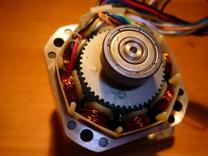
Direct Current brush motors rotate continuously when voltage is applied to their terminals. Stepper motors and stepper motor controllers, on the other hand, effectively have multiple “toothed” electromagnets arranged around a central gear-shaped piece of iron. The electromagnets are energized by an external control circuit, such as a stepper motor micro controller. To make the stepper motor shaft turn, one electromagnet is given power, which magnetically attracts the gear’s teeth. When the gear’s teeth are aligned to the first electromagnet, they are slightly offset from the next electromagnet. So when the next electromagnet is turned on and the first is turned off, the gear rotates slightly to align with the next one, and from there the process is repeated. Each of those rotations is called a “step”, with an integer number of steps making a full rotation. In that way, the motor can be turned by a precise angle.
To learn more about stepper motor controllers, please visit the reference links below. For stepper motor controller repair and replacement quotes, contact Precision Electric.
References:
- http://en.wikipedia.org/wiki/Stepping_motor#Fundamentals_of_operation
- http://en.wikipedia.org/wiki/Stepping_motor
- http://www.stepcontrol.com/stepping101/stepping101_Overview_1.html