 https://www.precision-elec.com/wp-content/uploads/2013/12/difference-from-ac-dc-electric-motors-2.jpg
454
800
Craig Chamberlin
https://www.precision-elec.com/wp-content/uploads/2025/02/Precision-Electric-Logo-TEXT-ONLY-Color-NEW.png
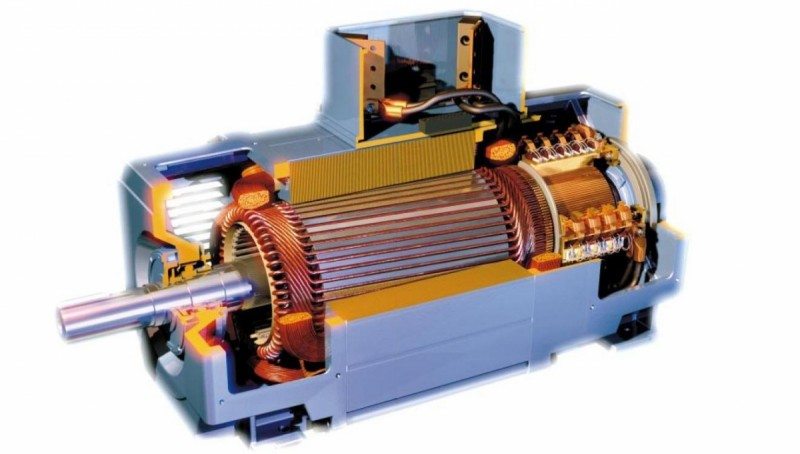
Craig Chamberlin2013-12-27 10:41:502018-04-23 13:16:08Difference From AC and DC Electric Motors
https://www.precision-elec.com/wp-content/uploads/2013/12/difference-from-ac-dc-electric-motors-2.jpg
454
800
Craig Chamberlin
https://www.precision-elec.com/wp-content/uploads/2025/02/Precision-Electric-Logo-TEXT-ONLY-Color-NEW.png
Craig Chamberlin2013-12-27 10:41:502018-04-23 13:16:08Difference From AC and DC Electric Motors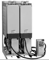 https://www.precision-elec.com/wp-content/uploads/2013/12/eaton-spi9000-vfd-system-drives1.jpg
198
162
Craig Chamberlin
https://www.precision-elec.com/wp-content/uploads/2025/02/Precision-Electric-Logo-TEXT-ONLY-Color-NEW.png
Craig Chamberlin2013-12-19 14:51:212018-02-01 16:14:55Eaton SPI9000 VFD System Drives
https://www.precision-elec.com/wp-content/uploads/2013/12/eaton-spi9000-vfd-system-drives1.jpg
198
162
Craig Chamberlin
https://www.precision-elec.com/wp-content/uploads/2025/02/Precision-Electric-Logo-TEXT-ONLY-Color-NEW.png
Craig Chamberlin2013-12-19 14:51:212018-02-01 16:14:55Eaton SPI9000 VFD System Drives https://www.precision-elec.com/wp-content/uploads/2013/12/abb-dcs800-drive-added-features-reduced-lead-time.jpg
924
1395
Craig Chamberlin
https://www.precision-elec.com/wp-content/uploads/2025/02/Precision-Electric-Logo-TEXT-ONLY-Color-NEW.png
Craig Chamberlin2013-12-18 11:18:522018-02-01 16:23:28ABB DCS800-EP Drive Updates
https://www.precision-elec.com/wp-content/uploads/2013/12/abb-dcs800-drive-added-features-reduced-lead-time.jpg
924
1395
Craig Chamberlin
https://www.precision-elec.com/wp-content/uploads/2025/02/Precision-Electric-Logo-TEXT-ONLY-Color-NEW.png
Craig Chamberlin2013-12-18 11:18:522018-02-01 16:23:28ABB DCS800-EP Drive Updates https://www.precision-elec.com/wp-content/uploads/2013/12/abb-frequency-converters-1.gif
308
530
Craig Chamberlin
https://www.precision-elec.com/wp-content/uploads/2025/02/Precision-Electric-Logo-TEXT-ONLY-Color-NEW.png
Craig Chamberlin2013-12-03 14:27:452018-02-01 16:33:12ABB Frequency Converters
https://www.precision-elec.com/wp-content/uploads/2013/12/abb-frequency-converters-1.gif
308
530
Craig Chamberlin
https://www.precision-elec.com/wp-content/uploads/2025/02/Precision-Electric-Logo-TEXT-ONLY-Color-NEW.png
Craig Chamberlin2013-12-03 14:27:452018-02-01 16:33:12ABB Frequency Converters


