 https://www.precision-elec.com/wp-content/uploads/2015/05/plastic-thermoforming.jpg
642
1140
Craig Chamberlin
https://www.precision-elec.com/wp-content/uploads/2025/02/Precision-Electric-Logo-TEXT-ONLY-Color-NEW.png
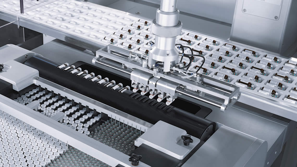
Craig Chamberlin2015-05-28 07:06:092015-07-31 11:41:47Plastic Thermoforming
https://www.precision-elec.com/wp-content/uploads/2015/05/plastic-thermoforming.jpg
642
1140
Craig Chamberlin
https://www.precision-elec.com/wp-content/uploads/2025/02/Precision-Electric-Logo-TEXT-ONLY-Color-NEW.png
Craig Chamberlin2015-05-28 07:06:092015-07-31 11:41:47Plastic Thermoforming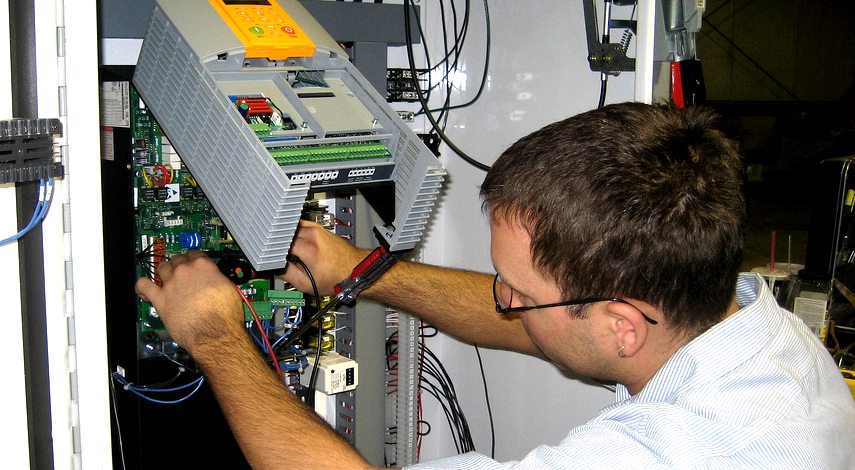 https://www.precision-elec.com/wp-content/uploads/2015/05/eaton-drives-troubleshooting.jpg
470
855
Craig Chamberlin
https://www.precision-elec.com/wp-content/uploads/2025/02/Precision-Electric-Logo-TEXT-ONLY-Color-NEW.png
Craig Chamberlin2015-05-19 08:56:152015-07-31 11:41:47Eaton Drives Troubleshooting
https://www.precision-elec.com/wp-content/uploads/2015/05/eaton-drives-troubleshooting.jpg
470
855
Craig Chamberlin
https://www.precision-elec.com/wp-content/uploads/2025/02/Precision-Electric-Logo-TEXT-ONLY-Color-NEW.png
Craig Chamberlin2015-05-19 08:56:152015-07-31 11:41:47Eaton Drives Troubleshooting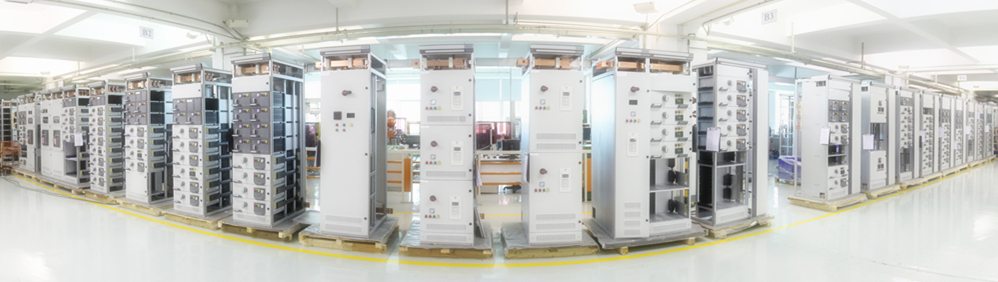 https://www.precision-elec.com/wp-content/uploads/2015/05/Electric-Motor-Service-Factor-123.jpg
282
998
Craig Chamberlin
https://www.precision-elec.com/wp-content/uploads/2025/02/Precision-Electric-Logo-TEXT-ONLY-Color-NEW.png
Craig Chamberlin2015-05-11 14:01:392015-07-31 11:41:47Electric Motor Service Factor
https://www.precision-elec.com/wp-content/uploads/2015/05/Electric-Motor-Service-Factor-123.jpg
282
998
Craig Chamberlin
https://www.precision-elec.com/wp-content/uploads/2025/02/Precision-Electric-Logo-TEXT-ONLY-Color-NEW.png
Craig Chamberlin2015-05-11 14:01:392015-07-31 11:41:47Electric Motor Service Factor https://www.precision-elec.com/wp-content/uploads/2015/05/motor-speed-controllers.jpg
388
620
Craig Chamberlin
https://www.precision-elec.com/wp-content/uploads/2025/02/Precision-Electric-Logo-TEXT-ONLY-Color-NEW.png
Craig Chamberlin2015-05-05 08:39:572015-07-31 11:41:47Motor Speed Controllers
https://www.precision-elec.com/wp-content/uploads/2015/05/motor-speed-controllers.jpg
388
620
Craig Chamberlin
https://www.precision-elec.com/wp-content/uploads/2025/02/Precision-Electric-Logo-TEXT-ONLY-Color-NEW.png
Craig Chamberlin2015-05-05 08:39:572015-07-31 11:41:47Motor Speed Controllers


