AC DC Industrial Electric Motors

AC DC industrial electric motors operate by applying alternating current (AC) or direct current (DC) power to itscorresponding AC or DC motor. AC DC industrial electric motors are seen in manufacturing equipment and other industrial rotating machinery.

The main parts of an AC electric motor arethe stator and rotor. The AC electric motor stator consists of wound coils that are supplied with alternating current power and produce a rotating magnetic field. The rotor will then rotate inside the electric motor coils and the output shaft produces torque via the rotating magnetic field. There are two different types of AC electric motors:

AC induction motors use a magnetic field on the rotor of an induction motor that’s created by an induced current. AC synchronous motors rotate at precise supply frequency or on a sub-multiple of the supply frequency.AC synchronous motors are able to operate with precision supply frequency because it doesn’t reply on an induced current. The magnetic field on an AC synchronous motor is generated by current delivered through slip rings or a permanent magnet. Most AC motors seen today are controlled by AC variable frequency drives (VFDs). Running a motor from a VFD can extend the lifespan of its corresponding motor increase energy efficiency within a manufacturing plant.

DC industrial electric motors are powered from direct current (DC) power and are mechanically commutated. DC electric motors have a voltage induced rotating armature windings and non-rotating armature field frame coils that are a static field or permanent magnet. DC electric motors use different motor connections of the field and armature winding to produce variable speed and torque outputs.DC industrial electric motor speed can be controlled within the winding by changing the voltage sent to the motor armature or by adjusting field frame current. Most DC electric motors today are manufactured to be controlled with DC drives. DC electric motors are used in many applications across the globe such as paper producing machines, steel mill rolling machines and other applications that require variable speed and torque output. Some obsolete machinery can be retrofitted with updated equipment by replacing a DC industrial electric motor with an AC industrial electric motor and AC variable frequency drive. Energy savings, increased production, increased quality control,anddecreased downtime are some of the benefits of integrating an AC motor and VFD to replace a DC motor.

Additionalinformation on AC DC industrial electric motors is available viathe linkswithin this post.Precision Electric integrates new applications and retrofits outdated equipment for manufacturers worldwide. Contact Precision Electric for AC DC industrial electric motors or other related equipment.

Electric Motor Service Factor

What does the electric motor Service Factor really mean?

The nomenclature of service factor on an electric motor nameplate is designated by “S.F.”. Service factor is a multiplier, which when applied to the rated horsepower, gives the allowable horsepower loading the machine is capable of delivering without causing significant damage to the unit.

Electric motor service factor is not a direct multiplier to motor current but it is a good rule to follow since horsepower output is often proportional to current draw.For most motors, using the service factor multiplier on the nameplate to the full load current rating will provide an accurate assessment of allowable full load current.There are some exceptional cases in which this rule may not apply. Operating an older until with lower efficiency ratings or operating in conditions in which power factoris low will create less temperature increase per ampere than in modern ‘T’ frame motors will heat up dramatically when operated over full load nameplate current ratings.

The key to maximum allowable current draw is how the draw in excess of nameplate will affect core heating and the ability of the core to dissipate that heat. Electric motor service factor should never be engineered into an application. Electric motors should never be operated within their service factors for prolonged time periods. The electric motor service factor must be viewed as insurance against motor failure during periods of temporary load or power problems.

If your electric motors are operating within service factor range, find out why. Correct the problem or at the very least, know the problem. Motors designed to operate on 460 volt systems will draw slightly higher current when operated at 480 volts. Units that have been rewound many times may have sufficient core losses to account for slightly higher current draw. These factors considered should emphasize the need for a class H insulating system on all rewinds.

To learn more about electric motor service factor or for repair and replacement quotes, contact Precision Electric.

How To Control How A Motor Starts And Stops

Nearly any three phase motor can be started and stopped with a variable frequency drive.

These motors can easily have different start and stop control methods performed by a variable frequency drive.

If you’re not familiar with the motor and drive industry, controlling a motor can be intimidating. Technology offers us many solutions when controlling motors and electronics, but not all of those solutions are equal. There are a number of different ways you can control how a motor starts and stops, and it all begins with a variable frequency drive.

Variable frequency drives give you complete control over your motor. You can control the start method, stop method, speed, direction and much more. They also offer several layers of protection to make sure your motor doesn’t get damaged in the process.

We would like to help you get exactly what you’re looking for. As a distributor of many variable frequency drives through our online store, we’re here to help you find the exact solution you need. In this instance, we will help you start and stop the motor in different ways.

How To Control How A Motor Starts

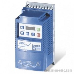
We begin with our personal favorite, the SMVector Series variable frequency drive. This drive is extremely versatile and cost effective. Once you’ve commissioned the drive, you can easily control how your motor starts and stops. Here’s how you do it:

  1. Press the menu button.
  2. If prompted for the password, use the arrow keys to select 0224 and press themenu button again.
  3. Scroll to parameter P110 and press the menu button again.
  4. Choose from one of the following start methods:
    • 00 – Normal – Drive starts when you press the start button. Start command must be applied at least 2 seconds after power-up; F_UF fault will occur if start command is applied too soon.
    • 01 – Start on Power-up – Drive attempts to start as soon as the unit is powered up. For automatic start / restart, the start source must be the terminal strip and the start command must be present.
    • 02 – Start with DC Brake – When start command is applied, drive will apply DC braking according to P174 and P175 prior to starting the motor.Start command must be applied at least 2 seconds after power-up;F_UFfault will occur if start command is applied too soon. If P175 = 999.99, DC braking will be applied for 15 s.
    • 03 – Auto Restart – Drive will automatically restart after faults, or when power is applied.For automatic start / restart, the start source must be the terminal strip and the start command must be present. Drive will attempt 5 restarts; if all restart attempts fail, drive displays LC (Fault lockout) and requires a manual reset.
    • 04 – Auto Restart with DC Brake – Combines Start on Power-up with Start with DC Brake.For automatic start / restart, the start source must be the terminal strip and the start command must be present.If P175 = 999.99, DC braking will be applied for 15 s.Drive will attempt 5 restarts; if all restart attempts fail, drive displaysLC(Fault lockout) and requires a manual reset.
  5. Once you’ve made a selection, press the menu button.

How To Control How A Motor Stops

Now that you’ve set how you want your SMVector series drive to start, you can select how you want it to react when it is configured to stop. Here’s how you do it:

  1. Press the menu button
  2. If prompted for the password, use the arrow keys to select 0224 and press the menu button again.
  3. Scroll to parameter P111 and press the menu button again.
  4. Choose from one of the following stop methods:
    • 00 – Coast – Drive’s output will shut off immediately upon a stop command, allowing the motor to coast to a stop.
    • 01 – Coast with DC Brake – The drive’s output will shut off and then the DC Brake will activate (refer to P174, P175)
    • 02 – Ramp – The drive will ramp the motor to a stop according to P105 or P126.
    • 03 – Ramp with DC Brake – The drive will ramp the motor to 0 Hz and then the DC Brake will activate (refer to P174, P175)
  5. Once you’ve made a selection, press the menu button

The Alternative Flying Start / Restart Method

The SMVector series also has the option to perform different types of flying starts and restarts. A “flying” start is a start that occurs while the motor is in motion. If you have an application that requires the motor stop and restart without completely stopping the motor, this option may be for you.Here are some things you need to consider.

Warning! Automatic starting / restarting may cause damage to equipment and / or injury to personnel! Automatic starting / restarting should only be used on equipment that is inaccessible to personnel.

  1. Press the menu button.
  2. If prompted for the password, use the arrow keys to select 0224 and press themenu button again.
  3. Scroll to parameter P110 and press the menu button again.
  4. Choose from one of the following start methods:
    • 05 – Flying Start / Restart – Type 1–Drive will automatically restart after faults or when power is applied. After 3 failed attempts, drive will Auto Restart with DC brake. This option performs a speed search, starting at max frequency (P103). If P110 = 0, a flying start is performed when a start command is applied.For automatic start / restart, the start source must be the terminal strip and the start command must be present.If P175 = 999.99, DC braking will be applied for 15 s.Drive will attempt 5 restarts; if all restart attempts fail, drive displaysLC(Fault lockout) and requires a manual reset. If drive cannot catch the spinning motor, drive will trip into F_rF fault. If drive trips into F_OF fault, try P110 = to 07 or 08.
    • 06 – Flying Start / Restart – Type 1–Drive will automatically restart after faults or when power is applied. After 3 failed attempts, drive will Auto Restart with DC brake. This option performs a speed search, starting at the last output frequency prior to faulting or power loss. If P110 = 0, a flying start is performed when a start command is applied.For automatic start / restart, the start source must be the terminal strip and the start command must be present.If P175 = 999.99, DC braking will be applied for 15 s.Drive will attempt 5 restarts; if all restart attempts fail, drive displaysLC(Fault lockout) and requires a manual reset.If drive cannot catch the spinning motor, drive will trip into F_rF fault. If drive trips intoF_OFfault, try P110 = to 07 or 08.
    • 07 – Flying Start / Restart – Type 2– For 2-pole motors requiring a flying restart.Drive will automatically restart after faults or when power is applied. After 3 failed attempts, drive will Auto Restart with DC brake. This option performs a speed search, starting at max frequency (P103). Type 2 utilizes P280 and P281 to set Max Current Level and Decel Time for restart.For automatic start / restart, the start source must be the terminal strip and the start command must be present.If P175 = 999.99, DC braking will be applied for 15 s.Drive will attempt 5 restarts; if all restart attempts fail, drive displaysLC(Fault lockout) and requires a manual reset.If drive cannot catch the spinning motor, drive will trip intoF_rFfault.
    • 08 – Flying Start / Restart – Type 2– For 2-pole motors requiring a flying restart.Drive will automatically restart after faults or when power is applied. After 3 failed attempts, drive will Auto Restart with DC brake. This option performs a speed search, starting atthe last output frequency prior to faulting or power loss. If P110 = 0, a flying start is performed when a start command is applied.Type 2 utilizes P280 and P281 to set Max Current Level and Decel Time for restart.For automatic start / restart, the start source must be the terminal strip and the start command must be present.If P175 = 999.99, DC braking will be applied for 15 s.Drive will attempt 5 restarts; if all restart attempts fail, drive displaysLC(Fault lockout) and requires a manual reset.If drive cannot catch the spinning motor, drive will trip intoF_rFfault.
  5. Once you’ve made a selection, press the menu button.

The Best Variable Frequency Drive For The Money

The SMVector Series drive is one of the most cost effective and versatile choices for controlling your motors start and stop method.

If you want complete control over every aspect of your motor, we recommend the SMVector Series variable frequency drive.

We offer a wide range of variable frequency drives that will fit your needs at our online store. Don’t hesitate to contact us if you have any questions or concerns when looking to purchase a variable frequency drive. We will get you taken care of.

You’ll likely have the most success, and save the most money, by purchasing an SMVector Series variable frequency drive. The SMVector drives areMade In America, include a 2 Year Manufacturer Warranty and the Price Includes Engineering & Application Support.

The performance and flexibility make the SMVector an attractive solution for a broad range of AC Motor applications and with several communications protocols available, networking drives and components into a system solution can be done now or in the future.

The SMVector NEMA 1 (IP31) is the most common and cost effective drive enclosure for a wide range of applications including packaging, material handling / conveying, positive displacement pumping, and HVAC systems.

The SMVector Series can be used with 3-phase AC induction motors and is available in NEMA 1 (IP31) , NEMA 4X (IP65) and NEMA 4X (IP65) with an integral disconnect switch. Filtered input versions of the SMV are available in NEMA 4X (IP65) models for compliance with the CE EMC directive.

Programmable digital and analog I/O allow the drive to be configured for many application specific tasks such as multiple preset speeds, electronic braking and motor jogging to name a few. Like all Lenze AC Tech sub-micro drives, the SMVector uses EPM memory technology for fast and efficient programming.

Technical documentation for the SMVector Series Drive, and all AC Tech brand drives, is available in our Technical Library.


AC Electric Motors

AC electric motors operate by applying alternating current (AC) power to the electric motor. The main parts of AC electric motors are the stator and rotor. The AC electric motors’ stator consists of coils that are supplied with alternating current power and produce a rotating magnetic field. AC electric motors rotor will rotate inside the electric motor coils and the output shaft produces torque via the rotating magnetic field.

There are two different types of AC electric motors and each of them uses a different type of rotor. The first type of AC motor is called an induction motor. Induction motors use a magnetic field on the rotor of an induction motor that’s created by an induced current. The other type of AC motor is called a synchronous motor and rotates precisely at the supply frequency or on a sub-multiple of the supply frequency. Synchronous motors are able to operate with precision supply frequency because it doesn’t reply on an induced current. The magnetic field on a synchronous motor is generated by current delivered through slip rings or a permanent magnet. Synchronous motors run faster than induction motors because the speed is reduced by the slip of asynchronous motors.

AC Electric Motors With Variable FrequencyDrives

Over the past decade, AC electric motors have been paired with variable frequency drives as a cost efficient way to reduce power costs and increase system production efficiency. Approximately one third of the world’s electrical energy is supplied by electric motors in fixed-speed centrifugal pump, fan, and air compressor applications. These fixed-speed applications don’t always require the full load speed (RPM) of the electric motor in which they’re operating. By installing a variable frequencydrive to these AC electric motor applications, the motor speed is reduced, and power costs can be reduced by 50% or more.This energy savings is often significant enough to cover the cost of a variable frequency drive within a few months.

Pairing AC electric motors with variable frequency drives is common in many applications such as swimming pool pumps, air compressors, conveyor belts, lathes, mills, food processing, plastic extrusion, waste water treatment pumps, HVAC fans and blowers, and many more. AC electric motors and variable frequencydrivesare used on machinery to increase or decrease the acceleration and deceleration times on alternating current (AC) motors.

Adjusting the acceleration and deceleration time of AC electric motors can extend the motor’s lifespan, and can also improve efficiency on production demands. Variable frequency drives on AC electric motorscan also provide the ability to control the frequency of starting and stopping an AC motor.This ability provides a means by which AC electric motors are only operating when needed for the equipment they’rerotating. AC electric motors have a longer lifespan if they’re not continuously operating when they don’t need to be.

To learn more about AC Electric Motors, Variable Frequency Drives, or for Repair and Replacement Quotes, Contact Precision Electric, Inc.


Preventing Electrical Bearing Damage Caused by VFD’s


FACT: Every motor controlled by a variable frequency drive (VFD) should have bearing protection.

WHY?: Variable frequency drives induce voltage to the electric motor’s shaft that discharges through the bearings. This voltage can cause severe pitting, excessive bearing noise and eventuallybearing failure (see picture below).

IT GETS WORSE: Not only the motor’s bearings are at risk but coupled equipment like gear boxes, encoders, brake motors, etc. are also at risk of damage.Installing a bearing protection ring on your electric motor will channel that shaft voltage away from your bearings andsafelyinto ground.


Electric Motor Bearing Failure

Pitting in a electric motor’s bearing cause by shaft voltage induced by a variable frequency drive


REMEMBER: Insulating bearing housings alone does not prevent shaft current from discharging through the electric motor’s bearings and coupled equipment.

SOLUTION: Precision Electric can help you protect your bearings. Its cheaper than you think and it stops you from paying frequent electric motor repair cost. For more information on pricing on bearing damage protection and general purpose and inverter duty electric motors,

Please call toll free: 877-625-2402.

We will do everything we can to minimize your down time and maximize yourproductivity.