VFD Hardware Failure: Diagnosis and Replacement Guide

Estimated reading time: 9 minutes

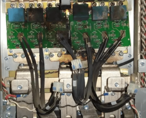
When a variable frequency drive (VFD) suffers a catastrophic hardware failure, it usually gives unmistakable warning signs. The user might hear a loud pop or bang. They might also see smoke or scorch marks. You may even find that the drive is completely dead with no lights on its panel. These alarming symptoms mean your motor is no longer under control. Your process could be at a standstill. In such urgent moments, a fast response is critical for safety. Reacting quickly also minimizes downtime.

This guide will walk you through how to diagnose the damage. You will learn to identify which components likely failed. We also cover when a repair is feasible versus when a full replacement makes more sense. A rapid, accurate diagnosis can save hours of lost production. Choosing the right replacement ensures your system is back up and running reliably.

Read more

Reading VFD Nameplate Data Off Of Your SMVector Drive (Video)

For those of you who are familiar or unfamiliar with Lenze / AC Techs SMVector series drive they have come a long way since their conception. All AC Tech products are manufactured in Uxbridge Massachusettes. Today we discuss how to read the nameplate data off of the drive. It is not as complicated as most might think. This is a great way to determine what voltage inputs, frequencies, phases are required and how to determine whether the Variable Frequency Drive itself is an adequate enough size for the motor you want to connect to it. Enjoy!

Eaton VFD System Drives

Eaton VFD system drives can reduce energy consumption from 10 to 50 percent by reducing the speed of an electric motor to its needed output speed. With reduced energy consumption, utility expenses are reduced and within a few months, the investment of Eaton VFD system drives can pay for themselves.

Eaton VFD system drives allow for steady speed error, fast torque rise time, high immunity to resonance vibrations and high starting torque and current. Eaton VFD system drives can be customized to fit multiple motor drive systems and high-speed applications. Eaton drives can be designed specifically for high-performance applications with high processing power, and the ability to use information from an encoder or resolver to provide precise motor feedback control. Eaton drives also offer a unique microprocessor to provide high dynamic performance for applications where precise motor handling and reliability are required.

The DG1 general-purpose Eaton VFD system drives are part of the Eaton next-generation PowerXL series. The DG1 general-purpose drive is specifically engineered for today’s more demanding commercial and industrial applications. Eaton DG1 drives offer an industry-leading energy efficiency algorithm, high short-circuit current rating and robust design, safety and reliability. The LCX9000 drive is liquid-cooled to utilize potable water or a water-glycol mixture as a cooling medium. The LCX9000 drive has a compact size and low heat transfer rates to allow the enclosure size to be greatly reduced, which is especially beneficial in UL Type 4X applications.

The PowerXL of Eaton VFD system drives is the next generation enclosed drive platform that packages Cutler Hammer’s PowerXL DG1 and SVX drive families in a fast and reliable design solution. The CFX9000 clean power of Eaton drives use tuned passive filters to significantly reduce line harmonics at the drive input terminals. These drives are an excellent choice for small and midsize applications where harmonics are a concern. The CPX9000 drives are used for water, waste water, HVAC, industrial and process industries where harmonics are present. They offer one of the purest sinusoidal waveforms available.

The SVX9000 of Eaton VFD system drives offer sensorless vector control technology coupled with an adaptive motor model and sophisticated ASIC circuit features. This technology allows for steady speed error, fast torque rise time, high immunity to resonance vibrations and high starting torque and current. The SVX9000 is suitable for multiple motor drive systems and high-speed applications.

Obsolete Eaton VFD System Drives

The MVX9000 Micro of Eaton drives are sensorless vector variable frequency drives that are designed to provide adjustable speed control of three-phase motors. Eaton SLX9000 are compact, powerful and are based on the more robust SVX9000. The SVX9000 is a newer version of the obsolete SLX9000. It is designed to be the next generation of drives specifically engineered for modern commercial and light industrial applications. The MVX9000 series of Eaton VFD system drives are obsolete and replaced by Cutler Hammer VFD Eaton M-MAX drives. The M-Max drive is a compact micro drive with a broad power range. The M-Max series features board coating, unique mounting characteristics, simple programming, and 50°C Rating to make the M-Max perfectly suited for machinery applications in many industries. Typical applications for the M-Max drives include Food and Beverage, HVAC, Packaging, Pumping, Textile, OEM, and more.

The HVX series of Cutler Hammer VFD drives are currently replaced by the Eaton H-MAX drives. The H-MAX series of HVAC VFD system drives are designed to the HVAC market for fan, pump, and fluid control applications. The patented energy savings algorithm, high short-circuit current rating and intuitive user interface provide customers an energy efficient, safe, and easy to use solution for variable frequency drive needs. The H-MAX drive supports the increasing demand for energy savings in buildings, systems and facilities. Built in capabilities and unique features provide a competitive solution that can add value to any end user.

For more information on Eaton VFD system drives, visit the Eaton Website. For Eaton VFD system drives repair and replacement quotes, Contact Precision Electric.

Delta Tau CNC Multi-Axis Automation Controls

We’ve Been Servicing the Industrial World Since 1983.

Minimize Your Downtime. Maximize Your Productivity.

Call Toll Free: 1.877.625.2402


Quite often, on more complex moves, such as moving a laser (2D Motion) in a circle or a robot arm (3D Motion) from picking up a box to setting it down, more than one motor is required. A system is considered “multi-axis” when it uses multiple motors or feedback (axes) coordinated together (coordinate systems) to perform one or more specific tasks.

CNC (Computer Numerical Control) simply illustrates the complexity of mathematics required for a high precision system. These systems often interface with an Industrial PC as their HMI.

Unfortunately we find many multi-axis / CNC systems utilize proprietary amplifiers (drives) and motor combinations. We pride ourselves in using Delta Tau controllers, which can be used with virtually any 3rd party drive and motor combination. This makes it the optimal controller to retrofit an already existing system or building a new one from scratch.

An example of a System Controller, known as the Delta Tau UMAC, the controller can simultaneously control up to 64 axes with extreme precision (within millimeters).

CNC and Multi-Axis Applications Include:

– Robot Packaging Systems
– Laser Cutting Machines
– Water Cutting Machines
– Procedural Systems
– Custom Machining Systems
– Patterning Systems
– Bending Systems
– High Precision Systems
– Robotic Painting Systems
– 2D Linear Motion Systems
– 3D Space Motion Systems
– And Much More…

Ryan Chamberlin
Inside Sales, Customer Support
[email protected]

ABB Frequency Converters

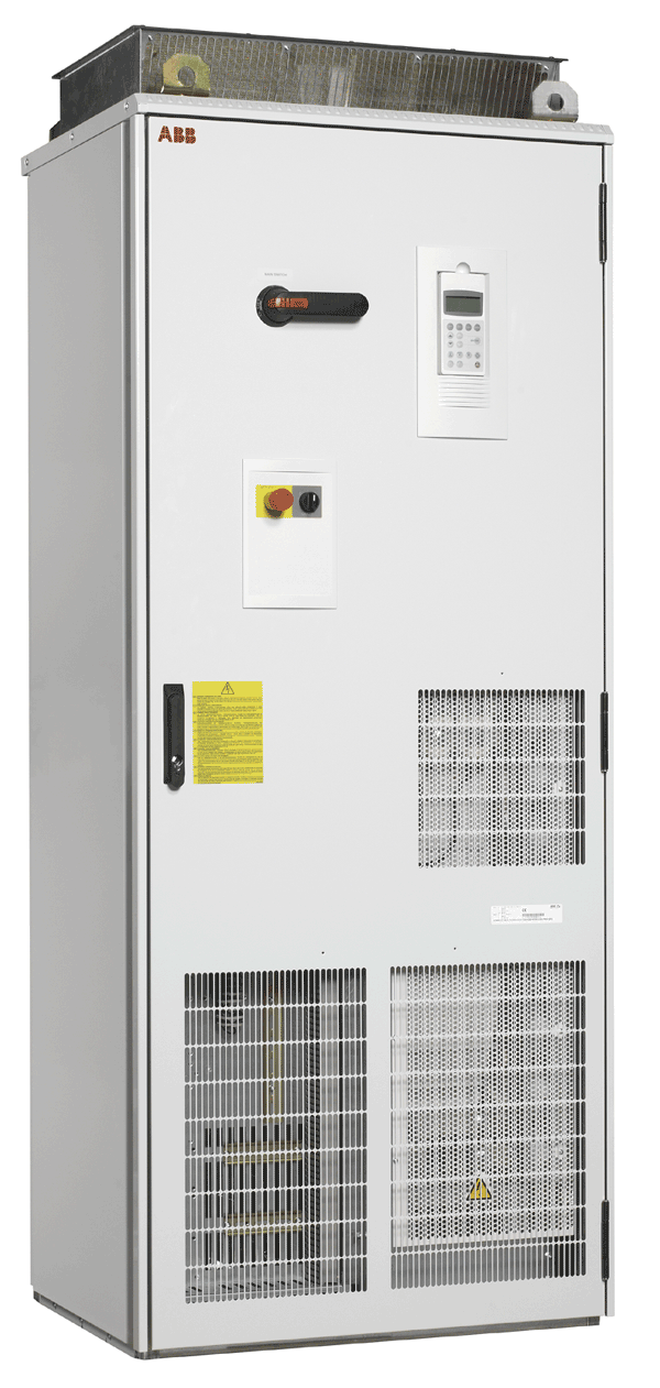
ABB Frequency Converters are used to change the frequency and magnitude of the constant grid voltage to a variable load voltage. Frequency converters are especially used in variable frequency AC motor drives.

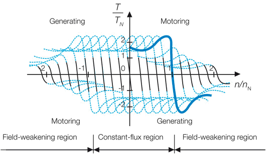
Figure 1 shows the behavior of an induction motor with several motor input voltages. The bold blue curve represents the electrical torque as a function of rotor speed when the motor is connected directly to a constant supply network. The blue portion of the torque curve shows the nominal load region (-1…+1 [T/TN]), which is very steep, resulting in low slip and power losses. Similar motor torque behavior with other motor input frequencies can be achieved by feeding the induction motor with a frequency converter and keeping the ratio of the magnitude and frequency of the motor voltage constant. As a result, the shape of the torque curve remains unchanged below the nominal speed (constant-flux region -1…+1 [n/nN]). In the field weakening region the motor voltage is at its maximum and kept constant, resulting in the torque curves being flattened.

ABB Frequency Converters Figure 1Fig. 1. Operation principle of the frequency converter fed induction motor.

ABB Frequency converters can be classified according to their DC circuit structure to voltage-source (Fig. 4), current-source (Fig. 3) and direct converters (Fig. 2). With a voltage-source converter the variable frequency and magnitude output voltage is produced by pulse-width modulating (PWM) the fixed DC voltage, whereas with a current-source converter the output voltage is produced by modulating the fixed DC current. With a direct frequency converter the variable output voltage is formed directly by modulating the constant input voltage. At low voltage applications (<1000 V) the voltage-source topology is mainly used.

ABB Frequency Converters Figure 2Fig. 2. Main circuit of the direct converter

ABB Frequency Converters Figure 3Fig. 3 Main circuit of the current-source converter

Fig. 4 shows a typical voltage source frequency converter structure where a constant DC voltage is formed by using an input diode rectifier. The output voltage with variable frequency and magnitude is produced by pulse-width modulating the inverter bridge. In more sophisticated frequency converters the input diode bridge can be replaced with a PWM bridge enabling a higher DC voltage, reactive power control, nearly sinusoidal supply network currents and regenerative operation of the inverter.

ABB Frequency Converters Figure 4Fig. 4. Main circuit of the commonly used voltage-source frequency converter. 

Fig. 5a shows the operation of the inverter bridge with two different output voltages. The desired output voltage is achieved by changing the width and polarity of the output voltage pulses. The higher the instantaneous value of the output voltage, the wider the output voltage pulse needed. Although the output voltage contains a lot of high order harmonic voltages due to the PWM, the motor current is nearly
sinusoidal since the motor inductances filter out the high order current harmonics.

Fig. 5b shows the construction of negative voltage pulses, circled in Fig.5, during one PWM period. The graphic on the right shows the switching states of the phases and the resulting U-V voltage. The graphic on the left shows the space vector presentation of the eight switching states of the voltage-source converter. These switching vectors are commonly used to achieve PWM (vector modulation). The ‘+’ and ‘-’ signs mean that the phase is connected to the positive or negative rail of the DC link respectively.

ABB Frequency Converters Figure 5Fig. 5a and 5b Operation of the voltage-source inverter with two different output voltage references and the principle of pulse width modulation.

To learn more about ABB Frequency Converters or to download technical information, visit the ABB Website.


Information References:


VFD Overvoltage Fault – troubleshooting variable frequency drives

A VFD overvoltage fault is fairly common with VFD regular usage. This fault may arise at different places and times for several reasons. The first step in resolving the problem is identifying when and where the fault occurs. A VFD overvoltage fault can occur on power up, during deceleration, acceleration, during normal run, or while sitting idle.

If the VFD overvoltage fault occurs during power up, the first thing to check is the incoming line voltage with a meter. If the line voltage is within specifications, find the jumper used to ground the common capacitors. This jumper will remove the common mode capacitors from ground. The VFD overvoltage fault may occur from ground noise coming back in through these capacitors causing a rise on the DC bus.

VFD overvoltage fault, at deceleration 

The most common time a VFD overvoltage fault occurs is during deceleration. Sometimes the braking torque requirement exceeds drive braking circuit capacity. Other times the deceleration is too fast for its load and inertia from the load is going faster than the designated frequency. If you hit stop during a ramp down, the load spins faster than the designated frequency, the motor regenerates power back into the drive. The motor load then turns into a generator. This power is fed back into the drive, and stored on the DC bus. Extending the deceleration time is one way to solve a VFD overvoltage fault during deceleration.

If extending the deceleration time does not solve the VFD overvoltage fault, a dynamic brake may be required to dissipate the excess energy. A dynamic brake is a resistive device that takes energy from the bus and burns it off as heat. The only other solution is to reduce the inertia on the load to the motor. How you do that is dependent on your application. A constant overhauling load may be a good application for a regenerative drive, where instead of a dynamic brake removing energy by converting it to heat, a regenerative unit will put the energy back on the utility line, and may even decrease your energy bill.

A VFD Overvoltage fault during acceleration is uncommon, but it has been known to happen on high inertia loads with extensive acceleration times. A flywheel is a common high inertia application with timely acceleration. During acceleration, these type of loads can actually speed up quicker than the motor due to inertia, and the load becomes regenerative. To solve an overvoltage during acceleration, try to reduce the accel time. It usually takes some experimenting and fine tuning before a technician is satisfied with the results and commits to an accel time setting.

VFD overvoltage fault, operating normally

If the output load has a clutch, that may cause a VFD overvoltage fault. If there is a sudden drop in load, the motor speed may increase quickly, causing a regenerative load. If this is the case, a dynamic brake might help absorb the energy. A dynamic brake removes energy from the bus and burns it off as heat. With a high voltage line, and an application where a conveyor becomes less loaded, may be enough to turn the motor into a regenerative load. The drive is only able to absorb regenerative power to a certain extent, but too much will cause a VFD overvoltage fault. If the load is known to be stable, and not changing torque requirements drastically, then check the incoming line to the drive.

VFD overvoltage fault, when sitting idle

When high incoming AC voltage is present A VFD overvoltage fault can occur while the drive is sitting idle. If this VFD overvoltage fault is sporadic, there’s something nearby that is causing the AC line to fluctuate. If you investigate large induction loads, see if they are causing the distribution line to change voltage. If an improperly tapped transformer is present, that can also cause an overvoltage fault by keeping the incoming line at the high end of the recommended voltage. This won’t allow much room for voltage changes on the DC bus, if they were to occur. Incoming line fluctuations may not be detected by a multi-meter. If the voltage rise is  quick and / or sharp, a multi-meter may not work fast enough to capture the reading. An oscilloscope or voltage monitor may be necessary to capture the voltage rise.
If the main incoming power line has power factor correction caps, switching in and out may also cause a large power spike. In this case, an isolation transformer or line reactor may be required on the front end of the drive to absorb the power spike.

Precision Electric offers drive repair and drive replacement for all manufacturer products. Precision Electric repairs AC and DC variable speed drives up to 3000 horsepower. Call Precision Electric for VFD repair and replacement quotes.


References: abb lv drives, ab rockwell

How To Control How A Motor Starts And Stops

Nearly any three phase motor can be started and stopped with a variable frequency drive.

These motors can easily have different start and stop control methods performed by a variable frequency drive.

If you’re not familiar with the motor and drive industry, controlling a motor can be intimidating. Technology offers us many solutions when controlling motors and electronics, but not all of those solutions are equal. There are a number of different ways you can control how a motor starts and stops, and it all begins with a variable frequency drive.

Variable frequency drives give you complete control over your motor. You can control the start method, stop method, speed, direction and much more. They also offer several layers of protection to make sure your motor doesn’t get damaged in the process.

We would like to help you get exactly what you’re looking for. As a distributor of many variable frequency drives through our online store, we’re here to help you find the exact solution you need. In this instance, we will help you start and stop the motor in different ways.

How To Control How A Motor Starts

We begin with our personal favorite, the SMVector Series variable frequency drive. This drive is extremely versatile and cost effective. Once you’ve commissioned the drive, you can easily control how your motor starts and stops. Here’s how you do it:

  1. Press the menu button.
  2. If prompted for the password, use the arrow keys to select 0224 and press the menu button again.
  3. Scroll to parameter P110 and press the menu button again.
  4. Choose from one of the following start methods:
    • 00 – Normal – Drive starts when you press the start button. Start command must be applied at least 2 seconds after power-up; F_UF fault will occur if start command is applied too soon.
    • 01 – Start on Power-up – Drive attempts to start as soon as the unit is powered up. For automatic start / restart, the start source must be the terminal strip and the start command must be present.
    • 02 – Start with DC Brake – When start command is applied, drive will apply DC braking according to P174 and P175 prior to starting the motor. Start command must be applied at least 2 seconds after power-up; F_UF fault will occur if start command is applied too soon. If P175 = 999.99, DC braking will be applied for 15 s.
    • 03 – Auto Restart – Drive will automatically restart after faults, or when power is applied. For automatic start / restart, the start source must be the terminal strip and the start command must be present. Drive will attempt 5 restarts; if all restart attempts fail, drive displays LC (Fault lockout) and requires a manual reset.
    • 04 – Auto Restart with DC Brake – Combines Start on Power-up with Start with DC Brake. For automatic start / restart, the start source must be the terminal strip and the start command must be present. If P175 = 999.99, DC braking will be applied for 15 s. Drive will attempt 5 restarts; if all restart attempts fail, drive displays LC (Fault lockout) and requires a manual reset.
  5. Once you’ve made a selection, press the menu button.

How To Control How A Motor Stops

Now that you’ve set how you want your SMVector series drive to start, you can select how you want it to react when it is configured to stop. Here’s how you do it:

  1. Press the menu button
  2. If prompted for the password, use the arrow keys to select 0224 and press the menu button again.
  3. Scroll to parameter P111 and press the menu button again.
  4. Choose from one of the following stop methods:
    • 00 – Coast – Drive’s output will shut off immediately upon a stop command, allowing the motor to coast to a stop.
    • 01 – Coast with DC Brake – The drive’s output will shut off and then the DC Brake will activate (refer to P174, P175)
    • 02 – Ramp – The drive will ramp the motor to a stop according to P105 or P126.
    • 03 – Ramp with DC Brake – The drive will ramp the motor to 0 Hz and then the DC Brake will activate (refer to P174, P175)
  5. Once you’ve made a selection, press the menu button

The Alternative Flying Start / Restart Method

The SMVector series also has the option to perform different types of flying starts and restarts. A “flying” start is a start that occurs while the motor is in motion. If you have an application that requires the motor stop and restart without completely stopping the motor, this option may be for you. Here are some things you need to consider.

Warning! Automatic starting / restarting may cause damage to equipment and / or injury to personnel! Automatic starting / restarting should only be used on equipment that is inaccessible to personnel.

  1. Press the menu button.
  2. If prompted for the password, use the arrow keys to select 0224 and press the menu button again.
  3. Scroll to parameter P110 and press the menu button again.
  4. Choose from one of the following start methods:
    • 05 – Flying Start / Restart – Type 1 – Drive will automatically restart after faults or when power is applied. After 3 failed attempts, drive will Auto Restart with DC brake. This option performs a speed search, starting at max frequency (P103). If P110 = 0, a flying start is performed when a start command is applied. For automatic start / restart, the start source must be the terminal strip and the start command must be present. If P175 = 999.99, DC braking will be applied for 15 s. Drive will attempt 5 restarts; if all restart attempts fail, drive displays LC (Fault lockout) and requires a manual reset. If drive cannot catch the spinning motor, drive will trip into F_rF fault. If drive trips into F_OF fault, try P110 = to 07 or 08.
    • 06 – Flying Start / Restart – Type 1 – Drive will automatically restart after faults or when power is applied. After 3 failed attempts, drive will Auto Restart with DC brake. This option performs a speed search, starting at the last output frequency prior to faulting or power loss. If P110 = 0, a flying start is performed when a start command is applied. For automatic start / restart, the start source must be the terminal strip and the start command must be present. If P175 = 999.99, DC braking will be applied for 15 s. Drive will attempt 5 restarts; if all restart attempts fail, drive displays LC (Fault lockout) and requires a manual reset. If drive cannot catch the spinning motor, drive will trip into F_rF fault. If drive trips into F_OF fault, try P110 = to 07 or 08.
    • 07 – Flying Start / Restart – Type 2 – For 2-pole motors requiring a flying restart. Drive will automatically restart after faults or when power is applied. After 3 failed attempts, drive will Auto Restart with DC brake. This option performs a speed search, starting at max frequency (P103). Type 2 utilizes P280 and P281 to set Max Current Level and Decel Time for restart. For automatic start / restart, the start source must be the terminal strip and the start command must be present. If P175 = 999.99, DC braking will be applied for 15 s. Drive will attempt 5 restarts; if all restart attempts fail, drive displays LC (Fault lockout) and requires a manual reset. If drive cannot catch the spinning motor, drive will trip into F_rF fault.
    • 08 – Flying Start / Restart – Type 2 – For 2-pole motors requiring a flying restart. Drive will automatically restart after faults or when power is applied. After 3 failed attempts, drive will Auto Restart with DC brake. This option performs a speed search, starting at the last output frequency prior to faulting or power loss. If P110 = 0, a flying start is performed when a start command is applied. Type 2 utilizes P280 and P281 to set Max Current Level and Decel Time for restart. For automatic start / restart, the start source must be the terminal strip and the start command must be present. If P175 = 999.99, DC braking will be applied for 15 s. Drive will attempt 5 restarts; if all restart attempts fail, drive displays LC (Fault lockout) and requires a manual reset. If drive cannot catch the spinning motor, drive will trip into F_rF fault.
  5. Once you’ve made a selection, press the menu button.

The Best Variable Frequency Drive For The Money

The SMVector Series drive is one of the most cost effective and versatile choices for controlling your motors start and stop method.

If you want complete control over every aspect of your motor, we recommend the SMVector Series variable frequency drive.

We offer a wide range of variable frequency drives that will fit your needs at our online store. Don’t hesitate to contact us if you have any questions or concerns when looking to purchase a variable frequency drive. We will get you taken care of.

You’ll likely have the most success, and save the most money, by purchasing an SMVector Series variable frequency drive. The SMVector drives are Made In America, include a 2 Year Manufacturer Warranty and the Price Includes Engineering & Application Support.

The performance and flexibility make the SMVector an attractive solution for a broad range of AC Motor applications and with several communications protocols available, networking drives and components into a system solution can be done now or in the future.

The SMVector NEMA 1 (IP31) is the most common and cost effective drive enclosure for a wide range of applications including packaging, material handling / conveying, positive displacement pumping, and HVAC systems.

The SMVector Series can be used with 3-phase AC induction motors and is available in NEMA 1 (IP31) , NEMA 4X (IP65) ¹ and NEMA 4X (IP65) ¹ with an integral disconnect switch. Filtered input versions of the SMV are available in NEMA 4X (IP65) models for compliance with the CE EMC directive.

Programmable digital and analog I/O allow the drive to be configured for many application specific tasks such as multiple preset speeds, electronic braking and motor jogging to name a few. Like all Lenze – AC Tech sub-micro drives, the SMVector uses EPM memory technology for fast and efficient programming.

Technical documentation for the SMVector Series Drive, and all AC Tech brand drives, is available in our Technical Library.


FAQ :: VFDs | How Do I Derate Three Phase Inputs For Single Phase Applications?

Often times those using a Variable Frequency Drive (VFD) may find themselves needing to connect a higher horsepower VFD to a single phase input power source.  Since most higher horsepower VFDs only accept three phase input as a power source, they are left with little options or alternatives. Don’t fret, there is a solution.

If you are using a Variable Frequency Drive (VFD) rated for three phase input and the only power source you have available to you is single phase input, then you can derate the Variable Frequency Drive (VFD) to accept the single phase input power source.   You can almost always use a VFD rated for three phase input with a single phase input power source.  Of course, if it is available, try to use a single phase input rated VFD if your power source is single phase.

When only a three phase input VFD is available, it is acceptable and common practice to derate the VFDto work with a single phase input power source.  Variable Frequency Drive (VFD) availability and installation procedures may vary from one manufacturer to another.

Before you derate your VFD, it is most important to ensure the VFD you are using is properly suited for your application.  The following are some basic guidlines to help you in determining whether or not your Variable Frequency Drive (VFD) is suitable for your application:

  1. Gather motor nameplate data including horsepower (HP), current (Amps),  motor voltage, input line voltage and power source phase.
  2. Determine which type of VFD your application will require. The type will fall under the category of either Volts per Hertz (V/Hz), closed-loop vector, or open-loop vector (Sensorless Vector).

The internal components of the three phase input Variable Frequency Drive (VFD) is rated for the appropriate current expected when three phase input power is applied.  When using single phase inputinstead, the line side current from the single phase is always higher.  To “derate” is the process of ensuring that these component are rated for the higher current that will flow from the single phase input instead of the three phase input.

You can derateVFD by:

  1. Determining the Horsepower of the Motor the VFD will be connected too, then
  2. Choosing VFD with a Horsepower higher than the Horsepower of the motor to compensate for the additional input current from the single phase power source.

The simplest formula used for these types of applications is:

VFD Input Current > Motor Current Rating * 1.73

The VFD input current must be equal to or greater than the Motor Current Rating * 1.73.

When installing most three phase input Variable Frequency Drives (VFDs) on an application where single phase input power is used, you will almost always connect the input line leads to L1 and L2 of the VFD.  L3 will be left open with nothing connected.  Consult with the VFD manufacturer or knowledgeable integrator to be sure.

Example Application to DerateThree Phase Input Variable Frequency Drive (VFD) to work with a Single Phase Input power source:

An application has a 230 VAC single phase input power source and needs to connect it to a conveyor that has a Variable Frequency Drive (VFD) connected to a 10 Horsepower 230 VAC 3 phase induction motor. Let us assume it has been determined that this application will operate well with a simple Volts per Hertz (V/Hz) VFD. The issue is, since there are no VFD manufacturers that offer a 10 Horsepower (HP) single phase input Variable Frequency Drive (VFD), we will need to derateVFD with a three phase input forsingle phase input. Most manufactuers of VFDs only offer products up to 3 Horsepower (HP) for single phase inputthree phase output; some products such as AC Tech SCF series do offer standard single phase inputthree phase output products available up to 5 Horsepower (HP) range.

The 10 Horsepower (HP) AC motor nameplate reveals that the motor is rated for approximately 27 amps at 230 VAC. We must use the equation above:

  • VFD Input Current > Motor Current Rating * 1.73
  • VFD Input Current > 27 Amps * 1.73
  • VFD Input Current > 46.71

Now it has been determined this application will need a 230 VAC 3 phase Volts per Hertz (V/Hz) Variable Frequency Drive (VFD) with an input current rated at or above 47.0 amps.

Our company’s VFD of choice is the AC Technology/Lenze SMVector (SMV) product.  Although this VFD is open-loop vector capable and this application only requires a standard Volts per Hertz (V/Hz) VFD, the AC Tech SMVector (SMV) VFD is a great alternative to any manufacturer of Volts per Hertz (V/Hz) products because the SMV is often the same price or cheaper as any other Volts per Hertz (V/Hz) product and can operate in either Volts per Hertz (V/Hz) mode or open-loop vector.  These VFDs are also available in both Nema 1 and Nema 4x enclosures.

Looking into the product catalog, we find an SMV model fitting the requirements available rated at 15 Horsepower (HP) that has a 230 VAC three phase input rated for 48 input amps.

Eaton HVAC Frequency Drives

Eaton HVAC frequency drives were specifically engineered for HVAC, pump and fluid control applications. The power unit makes use of the most sophisticated semiconductor technology and a highly modular construction that can be flexibly adapted to the customer’s needs. The input and output configuration (I/O) is designed with modularity in mind. The I/O is compromised of option cards, each with its own input and output configuration. The control module is designed to accept a total of five of these cards. The cards contain not only normal analog and digital inputs but also field bus cards.

The HVX series of Eaton HVAC frequency drives are obsolete and replaced by Eaton H-MAX drives. The HMAX series of Eaton HVAC frequency drives are designed to the HVAC market for fan, pump, and fluid control applications. The patented energy savings algorithm, high short-circuit current rating and intuitive user interface provide customers an energy efficient, safe, and easy to use solution for adjustable frequency drive needs. The H-MAX drive supports the increasing demand for energy savings in buildings, systems and facilities. Built in capabilities and unique features provide a competitive solution that can add value to any end user.

 MVX9000 And M-Max Eaton HVAC Frequency Drives

The MVX9000 series of Eaton HVAC frequency drives are microprocessor-based, sensorless vector drives that provide adjustable speed control for three-phase motors. MVX9000 drives come with standard features that can be programmed to customize the drive’s performance to suit a wide variety of applications, and they include a digital display with operating and programming keys on a removable keypad.

MVX9000 series of Eaton HVAC frequency drives are obsolete and replaced by Eaton M-MAX drives. The M-Max Drive is a compact micro drive with a broad power range. The M-Max series of Eaton HVAC frequency drives feature conformal board coating, unique mounting characteristics, simple programming, and 50°C Rating to make the M-Max perfectly suited for machinery applications in many industries. Typical applications for the M-Max Eaton drive include Food and Beverage, HVAC, Packaging, Pumping, Textile, OEM, and more.

The M-Max series of Eaton HVAC frequency drives key features include:

  • Global acceptance
  • 50C ambient temperature environments
  • Conformal coating standard
  • Modbus-RTU as standard serial fieldbus
  • Side-by-side mounting and orientation flexibility to maximize panel space
  • Temperature controlled cooling fan to increase efficiency and extend life
  • On-board start-up wizard and preset macros to simplify commissioning
  • NEMA 1 kits available

To learn more about Eaton HVAC frequency drives or for Eaton HVAC drives repair and replacement quotes, contact Precision Electric.

VFD Tripping GFCI Breaker: Lenze Drive Solutions & Fixes

Estimated reading time: 12 minutes

Have you ever dealt with your VFD tripping a GFCI breaker unexpectedly? If so, you’re not alone. Variable frequency drives (VFDs) often trip GFCI devices, especially in wet areas or where codes mandate GFCI protection. The result is nuisance tripping—the GFCI breaker shuts off repeatedly, even though your system has no real fault.

In this post, we’ll explain why VFDs trip GFCI breakers. You’ll also learn how to use GFCI devices with Lenze AC Tech drives (and other VFDs) without constant interruptions.

We’ll cover what GFCI devices do and why VFDs can inadvertently trigger them. Such as PWM, leakage currents, and parasitic capacitance. Most importantly, we’ll outline how to troubleshoot and prevent these trips.

By the end, you’ll know the key settings to adjust and cabling practices to follow. You’ll also know when to consider filters or alternate solutions. Our goal is to help you run your VFD with GFCI protection reliably – keeping both your equipment and personnel safe.

Read more

Lenze-AC Tech Variable Frequency Drive Products

Variable frequency inverters are used for electronic speed control of AC induction motors. The needs of the market are wide and varied, and we offer a broad range of standard products for everything from simple speed control to complex; each with a wide range of functionality, small physical size and exceptional performance. Our drives are reliable, flexible to apply, easy to commission, and meet the highest standards of quality. Lenze-AC Tech provide solutions to fulfill nearly any inverter requirement in the power range between 0.25 and 400 kW.

SMV Standard Enclosure

  • NEMA 1 (IP31)
  • 120V – 600V
  • 0.33 to 30HP ( 0.25 – 22kW)
  • Open-loop Vector, V/Hz

Washdown Enclosure

  • NEMA 4X (IP65)
  • 120V – 600V
  • 0.33 to 30HP ( 0.25 – 22kW)
  • Open-loop Vector, V/Hz

Integral Disconnect

  • NEMA 4X (IP65)
  • Integral Motor & Drive Disconnect
  • 0.33 to 10HP ( 0.25 – 7.5kW)
  • Open-loop Vector, V/Hz

MC Series

  • 120-590V
  • 00.25 to 150 Hp (0.18-110kW)
  • NEMA 1 (IP31), NEMA 4(X) (IP65), NEMA 12 (IP54)
  • V/Hz

MCH Series

  • 200-590V
  • 1.0 to 250 Hp (0.75-185kW)
  • NEMA 1 (IP31), NEMA 4(X) (IP65), NEMA 12 (IP54)
  • V/Hz

Lenze – AC Tech offers many other products including but not limited to servo drives, gearmotor drives, and more. To learn more about additional Lenze – AC Tech products please contact me direct.

Ryan Chamberlin
Inside Sales, Customer Support
[email protected]

Lenze Americas VFD Drives

Lenze Americas VFD Drives are high-performance products used to optimize new and existing machinery for production. Lenze is one of the leading drive and automation specialists in the field of machine engineering. Rapidly changing times present manufacturers with new and varied challenges. To succeed in the future, manufacturers will need to handle more extensive tasks in even shorter time frames; Lenze Americas aims to reach this ideal.

SMV Series: The SMV series of Lenze Americas VFD drives offer sophisticated auto-tuning and fast dynamic torque response. The SMV is designed for motor applications where dynamic speed and torque control is demanded. The SMV series is an attractive solution for a broad range of applications including: food processing machinery, packaging machinery, material handling, conveying systems, HVAC systems, and more. The SMV series uses an Electronic Programming Module (EPM) for programming. Maintenance techs can easily use the EPM to reconfigure drive parameters or reset the drive. When a drive reset is necessary on the SMV, customers can reset to factory default or preset settings within seconds. When SMV drives must be replaced, the parameter configuration can be saved by the user by simply plugging in the pre-programmed EPM.

MC1000 Series: The MC1000 Series of Lenze Americas VFD drives are the intelligent, versatile and cost-effective choice for industrial applications. From harsh environments to high torque loads, the M1000 Series drives meet the toughest requirements with reliability, at a low cost. Customers can easily program the MC Series and integrate extensive I/O with an array of programmable functions. The M1000 is available in power ranges of 1/4 to 150 HP. The MC1000 offers Enhanced Torque System (ETS). ETS allows maximum starting and accelerating torque and tight speed regulation, even under fluctuating load conditions. M1000 drives feature„ manual boost for high starting torque, and auto-boost for high torque acceleration at any speed. The M1000 features power-up & auto restart modes, sleep mode with adjustable speed threshold and time. The MC1000 also offers an optional Form C Relay and Dynamic Braking.

M3000 Series
The M3000 series of Lenze America VFD drives are for process control demands with fast acceleration and response. The M3000 is rated for constant torque applications but can easily be configured for variable torque applications. Most Process Control drives are designed for variable torque applications where the motor is driving a centrifugal fan or pump. As such, these drives are limited to 110% current for overload situations such as acceleration or responding to a feedback change. The MC3000 is a true Constant Torque drive rated for 180% of rated current for 30 seconds and 150% for one minute. This allows faster response to system changes and the ability to apply the MC3000 to non-centrifugal applications such as compressors, conveyors and other “constant torque” loads. The M3000 is available in the same power ranges and voltages as the M1000.

MCH Series: The MCH series of Lenze Americas VFD drives are available from 1 to 250 HP. The MCH series were designed for the HVAC market and specific requirements of industrial and commercial installations. The MCH series are designed to operate standard induction motors. The MCH Series offers intuitive operator interface using simple programming and operational information. The MCH series allows drive software to adjust the motor speed to maintain a preset pressure, flow, temperature or other variables using PID setpoint control. The MCH Series include UL and cUL approved motor protection for single motor applications. The MCH Series is seen in applications such as fans, pumps and cooling towers.

To learn more about Lenze Americas VFD drives, visit the Lenze Website. For Lenze Americas VFD Drives Repair or Replacement quotes, contact Precision Electric.