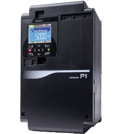
Full Title7.5 HP Hitachi SJ-P1 Series NEMA 1 Enclosed Variable Frequency Drive | 208 - 240 VAC 3 Phase Input | 240 VAC 3 Phase Output | 25 Amps | P1-00330-LFUF
SKUP1-00330-LFUF
Manufacturer
Hitachi
SeriesSJ-P1 Series
Availability
In Stock
Product Specifications
Horsepower
7.5 HP
Input Voltage(s):
200 - 240 VAC Input,
Output Voltage(s):
240 VAC Output
Rated Current:
25.0 Amps
Input Phase:
Three Phase Input
Output Phase:
Three Phase Output
Phase Converter
No
Enclosure:
IP20
UV Rating
None
Height
10 in
Width
8 in
Depth
7 in
Weight
15 lbs
Operating Modes
Sensor (Closed Loop) Vector Control (Requires Feedback Module), Sensorless (Open Loop) Vector Control, Speed Control (V / Hz), Torque Control (Constant), Torque Control (Variable)
Full Title10 HP Hitachi SJ-P1 Series NEMA 1 Enclosed Variable Frequency Drive | 208 - 240 VAC 3 Phase Input | 240 VAC 3 Phase Output | 32 Amps | P1-00460-LFUF
SKUP1-00460-LFUF
Manufacturer
Hitachi
SeriesSJ-P1 Series
Availability
In Stock
Product Specifications
Horsepower
10.0 HP
Input Voltage(s):
200 - 240 VAC Input,
Output Voltage(s):
240 VAC Output
Rated Current:
32.0 Amps
Input Phase:
Three Phase Input
Output Phase:
Three Phase Output
Phase Converter
No
Enclosure:
IP20
UV Rating
None
Height
10 in
Width
8 in
Depth
7 in
Weight
15 lbs
Operating Modes
Sensor (Closed Loop) Vector Control (Requires Feedback Module), Sensorless (Open Loop) Vector Control, Speed Control (V / Hz), Torque Control (Constant), Torque Control (Variable)
Full Title15 HP Hitachi SJ-P1 Series NEMA 1 Enclosed Variable Frequency Drive | 208 - 240 VAC 3 Phase Input | 240 VAC 3 Phase Output | 46 Amps | P1-00600-LFUF
SKUP1-00600-LFUF
Manufacturer
Hitachi
SeriesSJ-P1 Series
Availability
In Stock
Product Specifications
Horsepower
15.0 HP
Input Voltage(s):
200 - 240 VAC Input,
Output Voltage(s):
240 VAC Output
Rated Current:
46.0 Amps
Input Phase:
Three Phase Input
Output Phase:
Three Phase Output
Phase Converter
No
Enclosure:
IP20
UV Rating
None
Height
10 in
Width
8 in
Depth
6 in
Weight
15 lbs
Operating Modes
Sensor (Closed Loop) Vector Control (Requires Feedback Module), Sensorless (Open Loop) Vector Control, Speed Control (V / Hz), Torque Control (Constant), Torque Control (Variable)
Speed Control (V / Hz), Torque Control (Constant), Torque Control (Variable)
Analog Input(s)
1 Input (0 - 10 VDC), 1 Input (4 - 20 mA)
Analog Output(s)
2 Outputs (0 - 10 VDC / 2 - 10 VDC / 4 - 20 mA)
Control Input(s)
6 Inputs (NPN)
Control Output(s)
1 Output (Relay), 2 Outputs (NPN)
Integrated EPM Module:
No
Integrated Keypad:
Yes
Integrated Fwd / Rev Switch:
No
Integrated Speed Pot:
No
Integrated Disconnect:
No
Integrated Brake Chopper:
No
Integrated Communications:
Modbus RTU (RS-485)
Learn More
You can hover your mouse over highlighted product specs to learn more.
Description
Estimated reading time: 12 minutes
An Introduction to Lenze AC Tech MCH Variable Frequency Drives VFDs
The Lenze AC Tech MCH series represents a robust and versatile line of motor controllers specifically engineered for demanding industrial and commercial applications, especially within the HVAC sector. These Lenze AC Tech MCH variable frequency drives (VFDs) provide precise and efficient control over three-phase AC induction motors, resulting in significant energy savings and improved system performance. For instance, their design is tailored for environments like pumping and ventilation, where reliability is paramount. According to Amazonaws, the MCH series is available in both NEMA 1 and NEMA 12 enclosures, ensuring suitability for various installation environments. Consequently, this adaptability makes them a go-to choice for engineers seeking dependable motor control solutions.
Lenze AC Tech MCH VFD Power & Energy Savings
At the core of the MCH series is its impressive technical capability, offering a wide power range from 1 to 250 horsepower and accommodating multiple input voltage classes, including 208/240V, 480V, and 590V. This flexibility allows a single drive family to cover a vast array of motor sizes and power requirements. A key benefit of implementing a Lenze variable speed drive is the potential for substantial energy reduction, which is a major consideration in modern facility management. As documented by Valinonline, the drives feature a broad input voltage tolerance, enhancing their resilience in facilities with fluctuating power quality. Furthermore, the focus on efficiency aligns with rising energy costs, making these VFDs a smart investment, a point echoed by Borderstates.
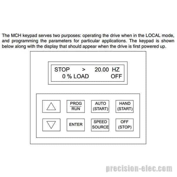
Beyond pure performance, Lenze AC Technology designed the MCH series with the technician and engineer in mind, emphasizing ease of use from installation to commissioning. As an AC Tech motor controller, it features an intuitive operator interface and a keypad with a clear, 32-character display that simplifies parameter setup. This user-friendly approach, highlighted by sources like Carotron, reduces programming time and minimizes the learning curve for maintenance personnel. Ultimately, the combination of robust hardware, flexible performance, and straightforward operation makes the MCH series a highly effective tool for achieving precise motor control and operational efficiency in any facility.
Unboxing and Pre-installation: First Steps for Your Lenze VFD
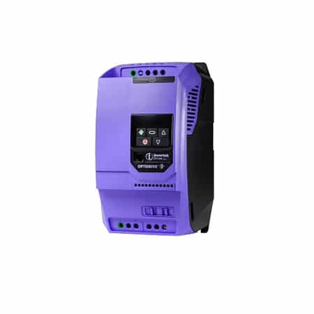
Upon receiving your new Lenze AC Tech MCH variable frequency drives VFDs, the first step is a thorough inspection before any power is applied. Carefully unbox the unit and check for any signs of physical damage that may have occurred during shipping, such as cracked plastic, bent heatsink fins, or loose components. It is crucial to verify that the model number on the drive’s nameplate matches your purchase order and is appropriate for the intended motor’s voltage and horsepower rating. Cross-referencing the nameplate data with the official specifications, like those found in the Valinonline installation manual, ensures you have the correct equipment for the job.
Assessing MCH VFD Installation Environment
Before proceeding to installation, assess the planned mounting location for environmental compliance. For instance, the MCH series offers various enclosure types, such as NEMA 1 and NEMA 12, to suit different operating conditions as detailed by Amazonaws. Ensure the ambient temperature, humidity, and potential exposure to dust or moisture are within the drive’s specified limits to prevent premature failure. In addition, always treat the VFD as an energized component until all power sources are verified to be disconnected and proper Lockout/Tagout (LOTO) procedures are in effect, adhering to NFPA 70E safety standards. This initial safety discipline is fundamental for protecting both personnel and equipment.
Finally, gather all necessary documentation and tools. Having the AC Tech MCH manual readily available is essential for referencing wiring diagrams and programming parameters later. You should also confirm that you have the correct wire gauges, circuit protection, and mounting hardware as specified by the manufacturer and the National Electrical Code (NEC). According to the Department of Energy, proper installation is a key factor in achieving motor efficiency. Consequently, taking these preparatory steps ensures a smoother, safer, and more successful installation and commissioning process for your Lenze variable speed drive.
Illustrative image for lenze ac tech mch variable frequency drives vfds
Step-by-step MCH Inverter Setup and Wiring
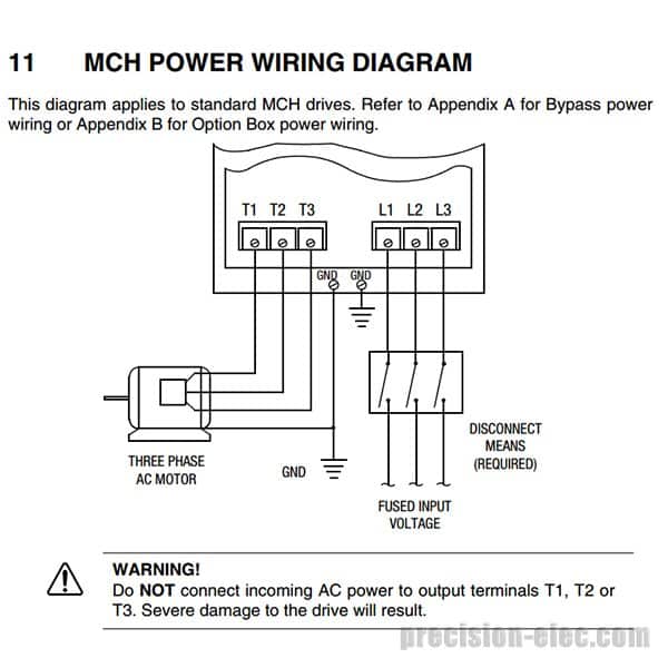
Proper MCH inverter setup is fundamental for ensuring the safety and longevity of Lenze AC Tech MCH Variable Frequency Drives (VFDs). Before beginning any wiring, it is absolutely critical to adhere to strict Lockout/Tagout (LOTO) procedures to de-energize the equipment completely, verifying a zero-Energy.gov Motor Tip Sheet state as required by NFPA 70E. Consequently, you must consult the official installation guide, as detailed by sources like Lenze MCH Series Manual, which provides the foundational schematic for all connections. This initial step prevents electrical shock hazards and protects both personnel and the drive from damage.
Once the system is safely de-energized, you can proceed with power wiring. First, connect the incoming AC power lines to the L1, L2, and L3 terminals and the motor leads to the T1, T2, and T3 output terminals. It is essential to use the appropriate wire gauge and circuit protection (fuses or breakers) as specified by the National Electrical Code (NEC) and the manufacturer's documentation found on sources like Amazonaws. Furthermore, always ensure that all connections are torqued to the specified values to prevent loose connections, which can lead to overheating and premature failure.
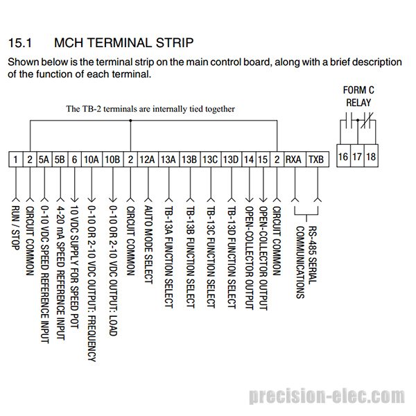
MCH VFD Control Wiring and Integration
In addition to power connections, control wiring is necessary for the drive's operation within a system. This involves connecting low-voltage signals for functions like start/stop commands, speed references (typically a 0-10 VDC or 4-20 mA signal), and digital inputs for preset speeds or other functions. For instance, these connections allow the VFD to be controlled remotely by a PLC or a building automation system. The MCH Series offers robust options for this integration, as outlined in technical overviews from Amazonaws and Lenze. Using shielded, twisted-pair cabling for all control signals is a best practice to minimize electrical noise.
Finally, proper grounding is a non-negotiable step for safe and reliable operation. The drive's chassis must be connected to a solid earth ground to provide a path for fault currents and reduce the risk of electrical shock. Moreover, using shielded VFD-rated cable for the motor connection is highly recommended to contain the high-frequency electrical noise generated by the drive's Pulse Width Modulation (PWM) output. As referenced in documentation from Lenze MCH Series Manual, failing to manage this noise can lead to interference with other sensitive electronic equipment in the facility.
Essential Lenze MCH VFD Programming Parameters
Effective Lenze MCH VFD programming begins with inputting the correct motor nameplate data. This foundational step is critical for protecting the motor and ensuring the drive operates efficiently. First, you must enter basic parameters such as motor voltage, full load amps (FLA), horsepower (or kW), and the maximum speed (RPM). Entering this data accurately allows the AC Tech motor controller to establish the correct protective limits and control envelope. For instance, an incorrect FLA setting can lead to nuisance tripping or, conversely, fail to protect the motor from an overcurrent condition. Therefore, always double-check these values against the physical motor nameplate before proceeding with further configuration.
Configuring Lenze MCH VFD Essential Parameters
Once the basic motor data is set, the next essential parameters to configure are the acceleration and deceleration times, minimum and maximum frequency, and the desired speed reference source. Acceleration and deceleration rates control how quickly the motor ramps up to speed and slows down, which is crucial for preventing mechanical stress on equipment. Similarly, setting the minimum and maximum frequency defines the operational speed range of the connected load. As detailed in the official manual from Lenze MCH Series Manual, these settings directly impact equipment longevity and process control. The speed reference can be set to the keypad, a remote potentiometer, or an analog signal from a PLC, depending on the application's needs.
Illustrative image for lenze ac tech MCH variable frequency drives vfds
Selecting the correct Voltage-to-Frequency (V/Hz) pattern is another vital programming step that directly influences motor torque and energy consumption. For constant torque applications like conveyors, a linear V/Hz profile is typically best. However, for variable torque loads such as centrifugal pumps and fans, selecting a squared or variable V/Hz profile is far more efficient. This setting allows the drive to reduce the voltage applied to the motor at lower speeds, significantly cutting energy use as documented by Amazonaws. In addition to standard profiles, the Lenze variable speed drive offers advanced settings like slip compensation to maintain precise speed under varying loads. The intuitive keypad, referenced by Amazonaws, simplifies this by displaying full words for parameters, reducing the need to constantly consult a manual. For complex setups, using the Lenze TechLink software can further streamline the process.
Decoding Common AC Tech VFD Fault Codes
Effective Lenze drive troubleshooting often begins with understanding the messages on the VFD's display. When your Lenze AC Tech MCH variable frequency drives VFDs encounter an operational issue, it typically initiates a protective stop and shows one of several AC Tech VFD fault codes. These codes are essential diagnostic tools that point technicians toward the root cause of the problem. For instance, instead of guessing why a motor stopped, the fault provides a clear starting point. A comprehensive list of these codes and their meanings is available in the official documentation provided by sources like Lenze MCH Series Manual, an invaluable resource for any technician.
Some of the most frequent faults are overcurrent (OC) and overvoltage (OV). An overcurrent fault indicates the motor is drawing excessive current, perhaps due to a mechanical jam or overly aggressive acceleration settings. On the other hand, an overvoltage fault occurs when the VFD’s DC bus voltage exceeds its limit, often caused by high line voltage or rapid deceleration of a high-inertia load. These drives have robust protective features against such events, including line voltage monitoring as detailed by Lenze MCH Series Manual. Consequently, investigating these faults involves checking for mechanical binding and verifying parameters.
Similarly, undervoltage (UV) and drive overheat (OH) faults are common. A UV fault triggers when incoming AC line voltage dips below the minimum threshold, protecting the drive's internal Insulated Gate Bi-polar Transistor (IGBT) components. In contrast, an overheat fault suggests the drive's temperature has surpassed its safe operating limit, as specified in technical documents like those from MCH Series Drives. Common causes include blocked ventilation, cooling fan failure, or high ambient temperatures. Therefore, the first troubleshooting steps should include verifying the power source and ensuring adequate airflow.
Beyond these, the MCH series can also display faults for external trips (E-trip) or communication loss. The drive is capable of logging previous faults, which helps technicians identify intermittent issues, a feature highlighted in its specifications MCH Series Drives. Before attempting any physical inspection, it is critical to follow proper Lockout/Tagout (LOTO) procedures to de-energize the equipment. Always consult the specific AC Tech MCH manual for detailed troubleshooting steps to ensure a safe and effective resolution.
Systematic Lenze Drive Troubleshooting Techniques
When issues arise with Lenze AC Tech MCH variable frequency drives VFDs, a systematic approach to troubleshooting is essential for safe and efficient resolution. Before any hands-on diagnostics, always adhere to strict Lockout/Tagout (LOTO) procedures to de-energize the equipment, complying with NFPA 70E standards. The first step in any Lenze drive troubleshooting process involves observing the drive’s display for any active AC Tech VFD fault codes, which provide immediate direction for your diagnostic efforts. For instance, an overvoltage fault might point towards incorrect deceleration settings or external power issues. Cross-referencing these codes in the official technical manual is critical; consequently, having documentation like the Lenze MCH Series Manual manual readily available can save significant time.
AC Tech MCH VFD: Visual Inspection & Electrical Tests
Illustrative image for lenze ac tech MCH variable frequency drives VFDs
Following the initial fault code analysis, a thorough visual inspection is necessary. Check for loose terminal connections, signs of overheating such as discoloration, and any damage to components or wiring. Subsequently, proceed with basic electrical measurements using a quality multimeter. First, verify that the incoming three-phase AC voltage is balanced and within the drive’s specified tolerance, which is typically +10% to -15% as noted in documentation from MCH Series Drives. Next, measure the DC bus voltage at the designated terminals; it should generally be around 1.414 times the incoming AC voltage. In addition, confirm the motor winding continuity and resistance to ground to rule out motor faults, a common cause of drive trips. Poor motor condition can significantly impact VFD performance and overall energy efficiency, a key consideration highlighted by the Department of Energy.
If electrical checks and visual inspections do not reveal the problem, the next area to investigate is the Lenze MCH VFD programming. Inadvertent parameter changes can lead to erratic behavior. Therefore, it is good practice to review critical settings like acceleration/deceleration times, motor data, and V/Hz patterns to ensure they match the application's requirements. Comparing the current configuration against a known-good backup file can quickly identify discrepancies. Tools like Lenze's TechLink software can simplify this process, allowing for easy parameter management. According to Lenze IF0008w PDF, proper parameterization is crucial for optimal performance. By methodically working from fault codes to physical inspections and finally to software parameters, technicians can diagnose and resolve nearly any drive issue effectively.
Preventive Maintenance for Your Lenze AC Tech MCH VFDs
Proactive preventive maintenance is crucial for ensuring the long-term reliability and optimal performance of your Lenze AC Tech MCH variable frequency drives VFDs. Establishing a regular inspection schedule can significantly reduce the risk of unexpected failures and costly operational downtime. Consequently, a well-maintained drive will operate more efficiently, protecting your investment and ensuring process stability. For detailed component specifications, the official operational manual is an invaluable resource, as noted by sources like Lenze MCH Series Manual. Adhering to a maintenance plan is the most effective strategy for extending the service life of these critical components.
Physical inspections should be the first step in your maintenance routine. Before any work begins, always follow proper Lockout/Tagout (LOTO) procedures to de-energize the equipment. Visually inspect the AC Tech motor controller for any accumulation of dust or debris, particularly on the heatsinks and cooling fans, as this can lead to overheating. Additionally, you should verify that all terminal block connections are secure, since vibrations can cause them to loosen over time. The Motion Control MCH Series Drives documentation highlights the robust steel enclosures designed to protect internal components, but regular cleaning ensures thermal efficiency. A clean, cool, and dry environment is essential for any VFD's longevity.
Beyond visual checks, performing key electrical measurements provides insight into the Lenze drive's health. Periodically verify input and output voltages and currents to ensure they are balanced and within the drive's rated specifications, as detailed in technical documents from Motion USA MCH Series Drives. It is also important to check the DC bus voltage to ensure the capacitors are functioning correctly. These checks help identify potential issues with incoming power or the connected motor before they escalate. For instance, consistent monitoring can alert you to conditions that might otherwise trigger the drive's low line voltage protection, a feature mentioned in guides from Lenze MCH Series Manual.
Conclusion: Maximizing the Performance of Your Lenze Variable Speed Drive
Ultimately, mastering your Lenze variable speed drive involves a comprehensive approach, from initial unboxing and wiring to advanced programming and diligent maintenance. This article has guided you through the essential steps for configuring, operating, and troubleshooting the Lenze AC Tech MCH series, ensuring you can harness its full potential for precise motor control. By following the detailed procedures for setup and understanding the logic behind programming parameters, you establish a solid foundation for reliable operation. Consequently, this diligence translates directly into enhanced system efficiency and can lead to significant energy savings, as highlighted by industry analysis from VFD Energy Savings. Proper initial handling and configuration are the first steps toward long-term performance.
To ensure the longevity and optimal performance of your MCH inverter, consistently applying best practices in preventive maintenance and safety is non-negotiable. Adhering strictly to Lockout/Tagout (LOTO) procedures and NFPA 70E guidelines protects both personnel and equipment during service. Furthermore, regularly consulting the official Lenze MCH Series Manual AC Tech MCH manual for specifications and fault code interpretations will empower your team to resolve issues swiftly. The robust design of these drives, detailed by MCH Series Drives, is built to last, but its lifespan depends on proactive care, including routine inspections for heat, vibration, and environmental contaminants. In other words, a proactive maintenance culture is your best insurance policy against unplanned downtime.
Read The Full Lenze Ac Tech MCH Variable Frequency Drives VFDs Research: