VFD Overvoltage Faults During Deceleration: Causes & Fixes
Estimated reading time: 13 minutes
Variable Frequency Drives (VFDs) are essential for controlling motor speed in industrial and commercial applications. However, VFD overvoltage faults are a common issue that often occurs when a motor is decelerating. An overvoltage fault will trip the drive to protect it, which can lead to unexpected downtime if not addressed promptly. These faults typically show up as a DC bus overvoltage alarm or error code on the drive. This halts your motor until the condition is cleared.
In this article, we’ll explain why VFD overvoltage faults happen during deceleration. We also describe the typical scenarios and symptoms, and walk through practical solutions to fix and prevent them. Our goal is to help you keep your drives running smoothly without nuisance trips – all in clear, easy-to-understand terms.
Why VFD Overvoltage Faults Happen During Deceleration
Regenerative Energy Surge
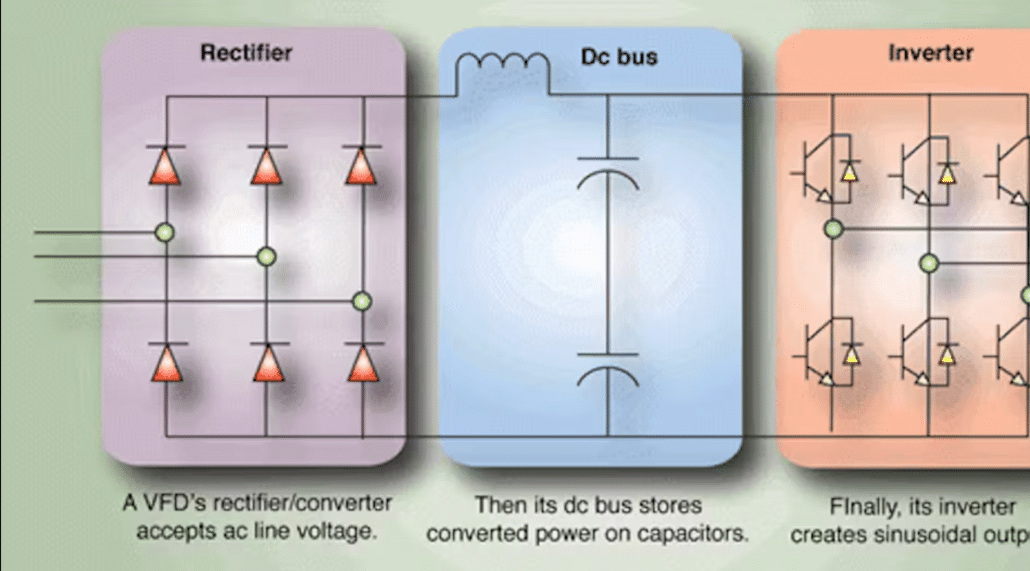
The main reason a VFD triggers an overvoltage fault during deceleration is regenerative braking energy. When you command a motor to slow down quickly, the motor doesn’t just stop on a dime – its inertia makes it keep spinning. In fact, the motor temporarily becomes a generator, feeding energy back into the drive instead of drawing energy. This returned energy causes the VFD’s DC bus voltage to rise. If the voltage spikes beyond the drive’s safe limit, the VFD trips on overvoltage to protect its components. In short, decelerating a motor too fast can push a surge of power back into the drive. This charges the DC bus like a battery and causing a DC bus overvoltage fault.
No Place For Excess Energy To Go
A standard VFD is designed with capacitors on the DC bus to smooth voltage, but those capacitors have limited capacity. During a rapid decel, the capacitors charge up quickly from the returning energy. If the drive doesn’t have a way to dissipate or redirect that energy, the DC bus voltage builds up until it hits the trip threshold. Think of it like slamming on the brakes in a car going downhill – the kinetic energy has to go somewhere. In a VFD, that “somewhere” is the DC bus. Without additional braking measures, a fast ramp-down will fill the DC bus with energy and trigger an overvoltage fault to prevent damage.
Overvoltage Fault Characteristics
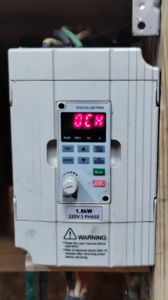
Overvoltage faults due to deceleration are usually repeatable and predictable. They tend to occur at the same point in the stopping process. For example, if you have a 5-second decel ramp set and the load is large, the drive might consistently fault 2–3 seconds into the decel when the motor’s regenerative output is highest. The drive’s display will likely show an alarm or fault code. This indicates high DC bus voltage (often labeled as “OV”, “DC BUS High”, or “Overvoltage”). Unlike some faults that occur randomly, regenerative overvoltage faults correlate directly with braking events.
Common Scenarios and Symptoms During Deceleration
Overvoltage faults during decel are especially common in certain scenarios. Recognizing these can help diagnose the issue:
Deceleration Set Too Fast For The Load
This is the classic case. Sometimes the VFD’s deceleration time is programmed too short for the inertia of the load. This can cause the motor to slow down faster than its mechanical system naturally allows. The result is a large surge of regenerative energy. For instance, a high-inertia fan or flywheel might coast longer than the VFD’s ramp time. The drive then sees a voltage spike as the spinning load feeds power back. A telltale symptom is the drive tripping **every time** you stop or slow down quickly. Simply put, the decel is “outrunning” the load, forcing the motor into generator mode and causing an immediate fault.
Heavy Lifting or Overhauling Loads
Certain applications inherently generate energy on decel. Consider a crane or hoist lowering a heavy load, or an elevator moving downwards. Here, gravity is driving the motor, and the VFD must absorb that energy. If the drive isn’t equipped to handle continuous regeneration, it will fault during the lowering stage. The symptom is an overvoltage alarm whenever the machine is braking a descending load. Even some horizontal systems with large inertia (like a long conveyor that’s stopping) can behave this way. The common factor is the motor is being “pushed” by the load during deceleration, leading to a regeneration event.
Intermittend Line Voltage Spikes During Stopping
In more rare cases, you might see an overvoltage fault at decel due to a combination of regen and a power supply surge. For example, if other machinery is switching on/off or power factor correction capacitors are on the same line, the AC line might spike at the same moment the drive is decelerating. This adds to the DC bus and can trigger a fault even if the decel alone was borderline. Symptoms here include the fault happening only occasionally during stops. Or perhaps more often at certain times of day or when other equipment cycles. It’s essentially a perfect storm of regenerative energy plus incoming line fluctuation. In such cases, adding a line reactor or surge suppressor alongside addressing regen may be needed.
How To Confirm It’s A Decel Overvoltage Fault
Most VFDs will log the fault code and maybe even the bus voltage at trip. Check your drive’s fault history to see when the overvoltage occurs. If it’s always during a slow-down or stop command, that’s a strong indicator. Also, if you extend the decel time as a test and the fault stops occurring, you’ve pinpointed the cause. Reviewing the drive’s manual or fault code list (for example, see our Cutler-Hammer VFD fault codes resource) can help verify the overvoltage diagnosis. The key symptom is a fault that consistently correlates with deceleration events.
How to Fix VFD Overvoltage Faults (Solutions)
Fortunately, there are several effective solutions to prevent regenerative overvoltage faults. In many cases, a bit of tuning or additional hardware can eliminate the problem. Below are common fixes, ranging from simple parameter changes to adding optional equipment:
Adjusting Deceleration Parameters Can Eliminate VFD Overvoltage Faults
Give The Motor Time To Slow Down
The easiest fix is often to increase the deceleration time in the VFD’s settings. By extending the ramp-down period, you allow the motor to shed energy more gradually. This means less regenerative surge back into the drive. For example, if your decel was 2 seconds, try 5 seconds or more and see if the fault goes away.
Many drives also have a setting for “overvoltage stall prevention” or “regeneration control”. This setting automatically lengthens the decel if a DC bus spike is detected. Enabling this feature (if available) can let the drive manage minor overvoltage conditions on its own. In some cases, changing the stop mode from “ramp” to “coast” can help too.
A coast-to-stop means the drive simply lets the motor spin down on its own without actively braking. This avoids generating any regenerative energy, though your stop may take longer. The downside of coasting is the motor takes longer to stop. If your process allows it, this can be an effective no-fault solution.
Use DC Injection Braking Cautiously
Another parameter-based tool is DC injection braking. This tool sets up the drive to inject DC current into the motor at the end of a ramp-down to quickly stop the motor. This method converts kinetic energy into heat in the motor rather than sending it back to the drive.
It’s useful for the final stopping of a high-inertia load without regen. However, use it carefully: too much DC injection or too long an injection time can overheat the motor windings. DC injection won’t help much if the majority of decel is regenerative; it’s mainly for the last part of stopping. Still, it’s an option in the drive’s toolbox that, when used appropriately, can reduce overvoltage trips during the final moments of deceleration.
Add a Dynamic Braking Resistor Can Eliminate VFD Overvoltage Faults
Burn Off Excess Energy As Heat
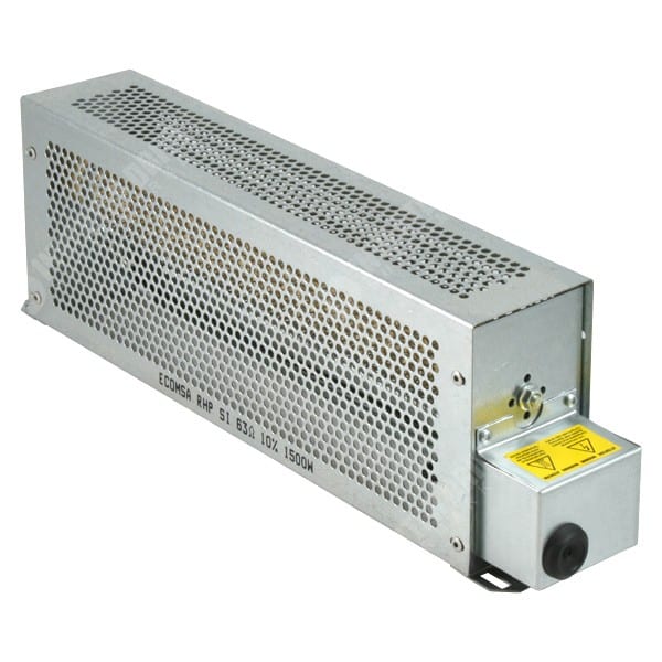
Sometimes adjusting parameters isn’t enough. the next solution is hardware: installing a dynamic braking resistor (sometimes just called a brake resistor). Most modern VFDs have an optional braking chopper circuit built-in or available. This is an internal transistor that, when activated, connects an external resistor across the DC bus.
During deceleration, if the DC voltage rises, the transistor opens the path to the resistor. The resistor then safely dissipates the extra energy as heat, preventing the DC bus from overcharging. In practical terms, a brake resistor acts like a pressure relief valve for the DC bus.
When sized correctly, it will absorb the bulk of the regenerative energy from the motor. This keeps the DC bus voltage below the trip threshold, so the drive won’t fault. Dynamic braking resistors are a common and cost-effective fix for overvoltage faults. They provide a path to bleed off regenerative energy.
Just be sure to get a resistor sized for your drive and application. You should consult the drive’s manual for the recommended resistance and wattage. Also, mount the resistor safely, as it will get hot when in use. With a proper braking resistor in place, even very rapid decel commands can usually be handled without tripping the drive.
Check Existing Brake Components If Faults Persist
If your VFD already has a braking resistor and you still get overvoltage faults, there may be an issue with the braking circuit. A few things to verify: Is the resistor properly connected and not open-circuited (a burned-out resistor won’t absorb energy)?
Is the braking transistor functioning? (A failed transistor means the resistor never gets switched in.) Also ensure the resistor’s size is adequate for your application. An undersized resistor can overheat and lose effectiveness, or simply not have enough capacity to absorb a large inertia stop.
Replacing a faulty resistor or transistor can restore the braking system’s performance. In short, if you’ve installed hardware to fix regen but the problem hasn’t gone away, double-check that hardware.
Upgrade to Regenerative Options To Leverage DC Overvoltage Faults
Feed the energy back to the grid or use a regen-ready drive. In applications with frequent or high-energy deceleration (like a centrifuge, elevator, or large crane), you might consider a regenerative solution instead of just dissipating energy. Regenerative VFDs and regen units send the excess energy back into the facility’s power system (or a common DC bus) rather than wasting it as heat.
This requires special hardware. Either a drive with an active front end (AFE) or a standalone regen module that connects to the DC bus. These solutions are more advanced and typically more expensive. The good new is they completely eliminate overvoltage trips by design. The energy is actively managed and returned to the source.
In fact, some facilities opt for regen drives to improve energy efficiency, especially if they have many braking events (the saved energy can reduce power consumption). For example, an active front end VFD can smoothly handle regenerative loads by inverting the power back onto the line by channeling the motor’s braking energy back into the AC line.
Choosing a regenerative approach makes sense when braking is a core aspect of your operation and you need a long-term solution for both energy savings and fault prevention.
Consider Drive Replacements Or Retrofits If Needed
Not all VFDs can accept braking resistors or have regen capability. Older or smaller drives might lack the built-in transistor for a braking resistor, and very few standard drives can do full regeneration without specialized hardware. If you find your current drive isn’t up to the task, it may be time to upgrade.
For instance, upgrading to a drive that has a built-in dynamic brake chopper or using a dedicated regen-capable VFD can solve persistent overvoltage issues. In some cases, using a larger drive (with higher power rating) provides more DC bus capacity and might ride through regen surges better.
**When choosing a new drive, make sure it’s rated for your application’s braking demands**. This might involve consulting with a drive specialist or the manufacturer. The investment in a properly sized or regen-equipped drive can pay off by eliminating downtime and extending the system’s life.
Is It Time for a Drive Upgrade?
How do you know when it’s necessary to move beyond tweaks and add-ons and opt for a different VFD altogether? Here are a few pointers:
- Frequent faults despite fixes: If you have already optimized decel times and installed a braking resistor, yet overvoltage faults still plague your process, your drive might be underpowered for the job. Consistent regenerative faults are a sign that you’re pushing the drive to its limits. Upgrading to a drive with higher capacity or one specifically designed for regenerative loads can provide the breathing room needed to handle your application.
- Drive lacks braking features: Some entry-level or older VFD models simply do not support dynamic braking or regen. If your unit doesn’t have terminals for a brake resistor or any mention of regen functions in the manual, you’re working with a limited toolset. Rather than fighting an uphill battle, consider retrofitting a drive that comes with those capabilities. Modern drives often include built-in brake chopper transistors and offer optional regen units for exactly this reason.
- Oversized load or changed application: Maybe your system’s requirements have grown – you attached a larger inertial load or the production demands faster cycle times than before. A VFD that was adequate in the past might now be undersized for the new conditions (leading to more frequent overvoltage trips during decel).
Selecting A Drive With Larger Horsepower Rating Can Be A Smart Move
In such cases, selecting a drive with a larger power rating or one designed for high-duty braking is a smart move. It’s better than constantly dealing with faults or nursing the old drive along. When evaluating replacements, look at both the horsepower and the braking torque specs. It’s wise to pick a drive that not only meets the running requirements but also can handle the braking energy without drama.
Upgrading doesn’t necessarily mean a huge expense either – sometimes a different model from the same manufacturer can be swapped in to give you the needed functionality. And if you’re unsure what to choose, reaching out to an expert for guidance can save a lot of trial and error. (For example, our team at Precision Electric can recommend preventive maintenance steps or suggest a suitable replacement drive based on your specific situation.)
The bottom line: if your VFD can’t be made to reliably handle deceleration without tripping, it’s likely time to consider a more capable unit.
Need Help With Persistent VFD Overvoltage Faults?
Contact the experts at Precision Electric for professional troubleshooting and drive replacement solutions. We’ve helped many clients resolve tricky VFD overvoltage faults by tuning drive parameters, adding brake resistors, or upgrading to regen-capable units. Don’t let repeated faults disrupt your operations – get in touch with Precision Electric for personalized assistance in keeping your drives running reliably.
*Internal Resources:* Browse our selection of AC Variable Frequency Drives if you need a new drive, and check out our guide on Preventive Maintenance for VFDs for tips to extend drive life. For help decoding other drive errors, see our overview of Cutler-Hammer VFD Fault Codes.


Trackbacks & Pingbacks
[…] retrofitting a drive. For practical selection and troubleshooting, see our cornerstone guides on VFD overvoltage on decel, VFD overcurrent, and VFD […]
[…] against overheating. For deeper fault coverage, see our cornerstone troubleshooting articles on overvoltage on deceleration, overcurrent and overload, and overheating and cooling […]
[…] when the load has high inertia or frequent stops; if symptoms persist, our troubleshooting guide on overvoltage during decel explains practical resistor sizing. Additionally, long motor leads can create reflected‑wave […]
[…] supply, explore our rotary phase converters. For troubleshooting tips read our guides on over‑voltage faults, cooling issues, over‑current trips and our ground‑fault […]
[…] the shop, so technicians need only land power leads on site. For more reliability tips, explore our overvoltage fault article and bookmark our overheating solutions […]
[…] for deeper technical reading you can review our internal guide on VFD overvoltage faults. You can also consult the external USU irrigation study that quantifies real‑world […]
[…] on legacy motors that lack inverter‑duty ratings. To explore fault‑specific guides—such as overvoltage at decel or parameter programming—visit our learning […]
[…] Age brings obsolescence. Manufacturers discontinue critical ASICs or microcontrollers after only ten years; therefore, buying a new board becomes impossible exactly when failure rates climb. Thankfully, disciplined circuit board repair addresses most of these environmental failures and remains a critical tool for reliability engineers. For deeper guidance on diagnosing over‑voltage events, see our VFD over‑voltage troubleshooting guide. […]
[…] a refresher on fault tracing? Our cornerstone guide on VFD overvoltage faults details oscilloscope methods that apply equally to servo drives. Likewise, the article covering […]
[…] insight matters, so bookmark our cornerstone guides: VFD overvoltage troubleshooting and the indepth VFD programming guide. For community feedback on emergency substitutions, review […]
[…] VFD Overvoltage During Deceleration […]
[…] VFD Overvoltage Faults During Deceleration: Causes & Fixes […]
[…] This requires a huge surge of current often more than the drives limit. As a result, the VFD will trip to protect itself. Similarly, slamming a motor to a stop (very short deceleration time) can force the motor into regenerative braking that sometimes manifests as high current (though it more often causes an overvoltage fault on the DC bus). […]
Comments are closed.