Line Reactor VFD: When to Use One for System Protection
Estimated reading time: 12 minutes
Introduction: the First Line of Defense for Your VFD Investment
Variable Frequency Drives (VFDs) are a cornerstone of modern industrial control, offering significant process improvements and energy savings. However, this sophisticated electronic equipment is also highly susceptible to disturbances on the incoming power line. For this reason, installing a vfd input reactor is a fundamental best practice for protecting your capital investment. As detailed by eaton.com, adding a line reactor is a critical step to mitigate electrical issues before they cause damage. This simple, passive component acts as a buffer, safeguarding the sensitive input components of the drive from a host of common electrical problems. Consequently, it is one of the most cost-effective reliability upgrades you can make to an AC motor control system.
AC Line Reactor: VFD Current Smoothing & Protection
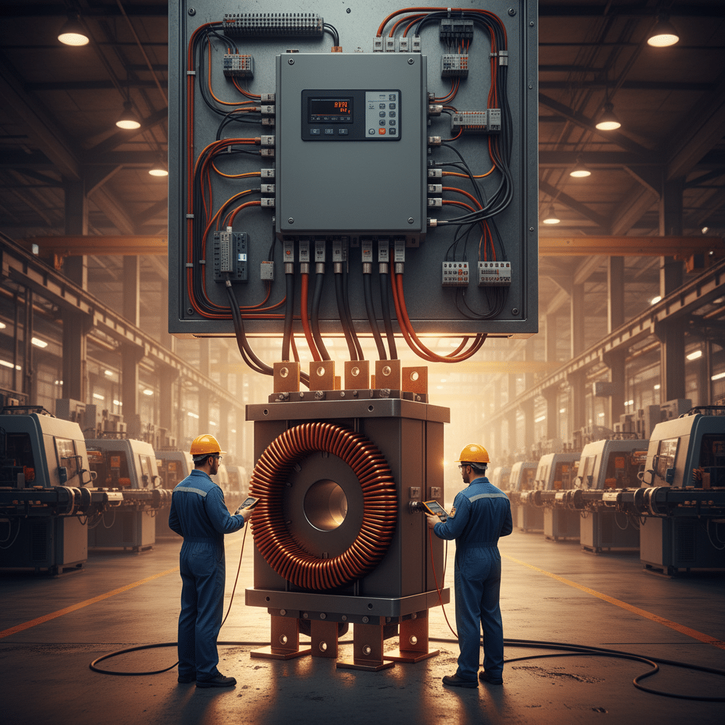
In essence, an AC line reactor is a type of inductor, consisting of a copper winding around a steel core, that adds impedance to the electrical circuit. This added impedance is crucial because it slows down the rate of current change, effectively smoothing the electrical current waveform drawn by the VFD. According to Transcoil Reactor Benefits Technical Paper, line disturbances are a frequent issue, making reactors a primary solution for drive protection. This simple device serves two main purposes: it provides VFD input protection against transient overvoltage events, and it mitigates the injection of harmonic distortion back onto the power system. In other words, it protects both the drive itself and other connected equipment.
Without this vital buffering, the VFD’s internal rectifier is directly exposed to power line anomalies such as voltage spikes, surges, and other transient events. These disturbances can lead to nuisance tripping, blown fuses, and, most critically, premature failure of the drive’s power components. The added impedance of a line reactor provides crucial protection against these surges, as explained by Eaton Line Reactors and Transients. Ultimately, investing in a properly sized line reactor vfd setup extends the operational life of the motor drive, improves overall system reliability, and helps ensure compliance with power quality standards like IEEE 519. It is an indispensable component for any robust VFD installation, as noted in a guide from EMIS Global Insights.
Understanding the Core Function of a Line Reactor VFD Setup
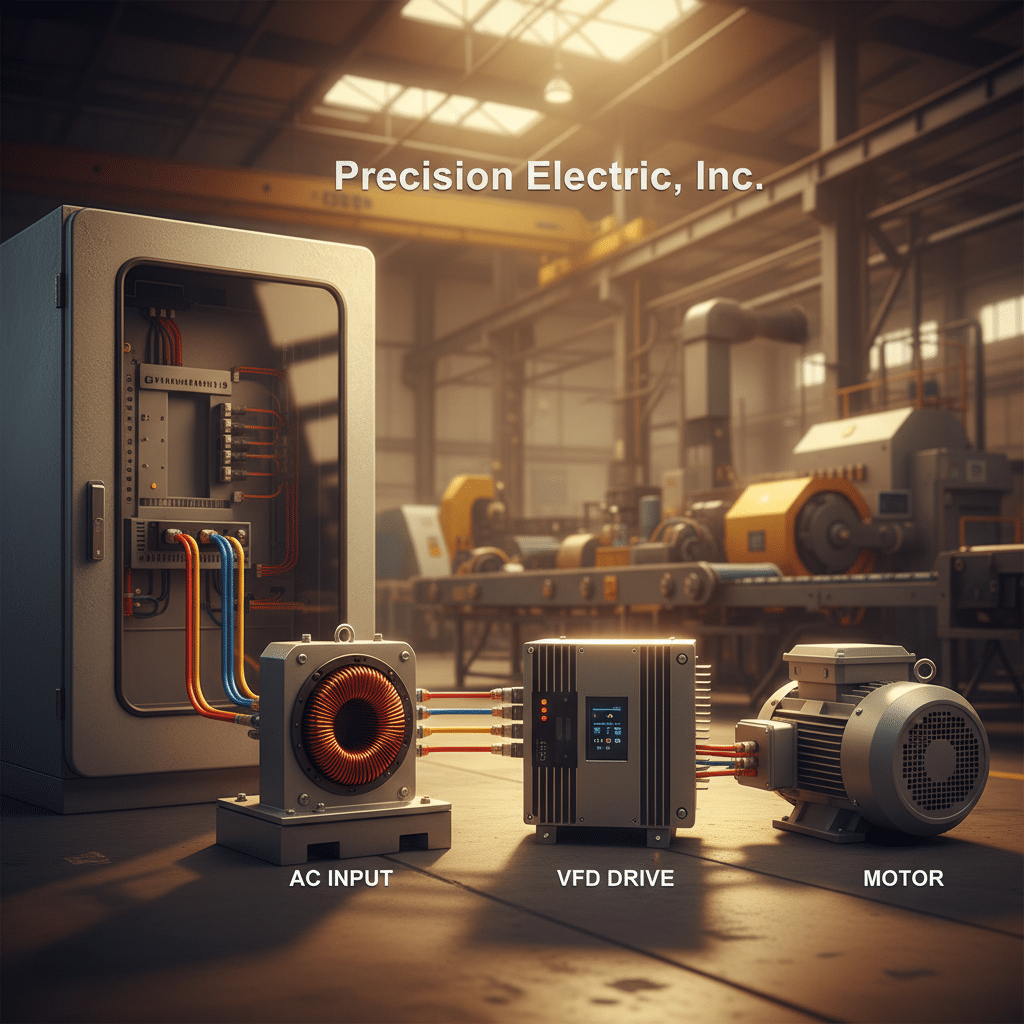
At its core, a line reactor VFD setup involves installing a simple, yet powerful, inductive component on the line (input) side of a Variable Frequency Drive (VFD). Essentially, a line reactor, also known as a drive input choke or an AC line reactor, is a coil of wire that creates a magnetic field as current flows through it. This device functions as a current-limiting buffer between the power source and the VFD. According to Transcoil Reactor Benefits Technical Paper, this simple addition introduces impedance, which is crucial for protecting the drive’s sensitive electronic components from power line disturbances.
How VFD Line Reactors Reduce Harmonics
The primary function of this added impedance is to slow down the rate of current change, effectively smoothing the electrical current drawn by the VFD’s rectifier. In other words, the VFD, without a reactor, draws current in short, high-amplitude pulses, which creates significant harmonic distortion. A 3-phase line reactor mitigates this by “choking” these pulses and broadening the current waveform. Consequently, this action not only reduces stress on the VFD’s internal components but also helps prevent nuisance tripping caused by transient overvoltage events, as noted by eaton.com. This stabilization is fundamental to both drive protection and improving overall Power Quality.
By performing this core function, the line reactor delivers two key benefits. First, it provides robust VFD input protection against sudden voltage spikes and surges from the power line. The added impedance buffers the drive from these potentially damaging events, extending the life of components like diodes and capacitors, a benefit highlighted by rae.ca. Second, it serves as an effective VFD harmonic filter, reducing the total harmonic distortion (THD) projected back onto the electrical system. This helps facilities maintain better Power Quality and comply with standards like IEEE 519. Many experts, including those at acim.nidec.com, consider reactors a cost-effective first step in harmonic mitigation.

An input line reactor is a critical first step in protecting your VFD investment from harmful electrical noise and voltage spikes, ensuring reliability.
The Critical Role of a VFD Harmonic Filter in Power Quality
A Variable Frequency Drive (VFD) operates by converting AC power to DC and then inverting it back to a simulated AC waveform, a process that makes it a non-linear load. Consequently, a byproduct of this operation is the introduction of harmonic currents back into the power system, making a vfd harmonic filter an essential component for maintaining power quality. These distorted currents can disrupt the smooth sinusoidal nature of the power supply, which, in turn, can negatively affect other sensitive electronic equipment connected to the same electrical network. Therefore, understanding and mitigating these harmonics is not just best practice but often a requirement for system reliability and compliance.
Addressing Harmonic Distortion with VFD Line Reactors
Harmonic distortion pollutes the electrical environment, causing issues such as overheating in transformers and neutral conductors, nuisance tripping of circuit breakers, and unreliable operation of electronic controls. According to Control Techniques Harmonic Mitigation, these disturbances can significantly degrade overall system efficiency and lead to premature equipment failure. In response, standards like IEEE 519 were developed to set limits on acceptable levels of harmonic distortion at the point of common coupling (PCC). Facilities must often take active measures to ensure their VFD installations comply with these standards, thereby protecting both their own equipment and the utility grid itself from the damaging effects of harmonics.
An ac line reactor is one of the most cost-effective and common solutions for mitigating these issues. By adding impedance to the input side of the VFD, the reactor smooths the current drawn by the drive’s rectifier, as explained by TransCoil Reactor Benefits. This action broadens the conduction angle of the input diodes, which dramatically reduces the amplitude of major harmonic currents, particularly the 5th and 7th harmonics. For instance, data from Hallam-ICS Harmonics Interpretation shows that a 3-5% impedance reactor can lower Total Harmonic Distortion (THD) from over 80% to a more manageable 30-40% range. In other words, this simple inductive device offers a crucial balance of performance and protection, as noted by Smartcoolingproducts, making the line reactor vfd combination a robust solution for cleaner power.
Protecting VFDs with an AC Drive Reactor
A crucial aspect of VFD input protection is installing an ac line reactor, which serves as the first line of defense against poor Power Quality. Variable Frequency Drives, with their sensitive electronic components, are highly susceptible to disturbances originating from the power line. For instance, according to Eaton Adjustable Frequency Drives, adding a reactor introduces necessary impedance to the system. This impedance helps stabilize incoming power and protects the drive from unpredictable electrical events.
Specifically, a drive input choke is engineered to absorb various power line issues that can damage a VFD. These common disturbances include voltage spikes, surges, and other forms of Transient Overvoltage, as detailed by Transcoil Reactor Benefits. The reactor’s core function is to act as an inductor, which naturally opposes rapid changes in current. In other words, this buffering effect smooths out sudden electrical events. It effectively prevents them from reaching the VFD’s sensitive rectifier and internal circuits.
Consequently, the main benefit of this protection is enhanced operational reliability and a longer VFD lifespan. A 3 phase line reactor absorbs line spikes and surges, which significantly reduces nuisance tripping from transient overvoltage, as noted by Smartcoolingproducts. Furthermore, this barrier safeguards sensitive components like diodes from premature failure, maximizing the system’s return on investment. As Emisglobal Guide to AC Line Reactors points out, it is a proven method to help extend overall motor life.

A line reactor, also known as a VFD input reactor, is installed on the line side of the drive to protect against power disturbances and reduce harmonic distortion.
Key Scenarios for Installing a VFD Input Reactor
Knowing when to install a vfd input reactor is a critical decision that impacts the longevity and reliability of an AC Motor and drive system. While many modern Variable Frequency Drives include some internal filtering, an external AC line reactor becomes essential in specific environments. For instance, facilities with poor Power Quality or significant line disturbances require this robust VFD input protection. As noted by TransCoil Reactor Benefits, such disturbances are common, making reactors a vital solution for drive protection. Therefore, assessing your electrical environment is the crucial first step.
Several specific situations strongly indicate the need for a 3-phase line reactor. For example, installations near large transformers or on systems with low line impedance can create high short-circuit currents. Eaton Adjustable Frequency Drives confirms that when line impedance is very low, adding external impedance is necessary. Another key indicator is the presence of power factor correction capacitors nearby, which can cause resonant conditions and lead to equipment damage. In addition, installing multiple VFDs on one line without reactors often compounds Harmonic Distortion, risking non-compliance with IEEE 519 and impacting other sensitive equipment.
Beyond mitigating harmonics, a drive input choke is also essential for protecting against Transient Overvoltage events. Power grids are susceptible to voltage spikes from utility switching, lightning strikes, or large load changes. A line reactor introduces added impedance that effectively buffers the VFD’s sensitive input rectifier from these damaging surges, a point highlighted by documentation from Eaton Line Reactors and Transients. In other words, this simple inductive device acts as the first line of defense against unpredictable power line events. Ultimately, using a motor drive reactor in these scenarios is not merely a recommendation but a foundational best practice for building a resilient and dependable automation system, as detailed in guides from RAE Line Reactor White Paper.
How to Size and Select the Right 3 Phase Line Reactor
Properly sizing a line reactor VFD setup is crucial for achieving the desired protection and performance. The primary factors for selection are the Variable Frequency Drive’s full load ampere (FLA) rating and the system’s nominal AC voltage. In essence, you must select a reactor with a current rating equal to or greater than the VFD’s input FLA. For instance, according to guidance from RAE Line Reactor White Paper, matching the reactor to the drive’s horsepower and current is a foundational step. Under-sizing a reactor can lead to overheating and premature failure, thereby negating its protective benefits.
The next critical parameter is the impedance rating, typically expressed as a percentage (e.g., 3% or 5%). This value represents the voltage drop across the reactor at full rated current. A 3% impedance reactor is standard for general-purpose applications, offering good harmonic mitigation and transient protection. In contrast, a 5% impedance reactor provides superior protection against more severe line disturbances, which is often recommended for systems with very low source impedance as noted by Eaton Line Reactors and Line Transients. However, it’s vital to balance this protection with the potential for increased voltage drop, which could affect motor performance under full load, a concept explained by Smartcoolingproducts.
Finally, consider the physical and environmental specifications. The reactor’s enclosure must be appropriate for the installation environment, such as a NEMA 1 for clean, dry indoor locations or NEMA 3R for outdoor applications. Moreover, verify the physical dimensions to ensure the unit fits within your control panel, allowing for adequate ventilation as reactors generate heat. As a best practice detailed by documents from Transcoil, always check the manufacturer’s datasheet for current ratings, impedance tolerance, and temperature rise specifications before finalizing your selection. This due diligence ensures the chosen 3 phase line reactor integrates seamlessly and reliably into your system.

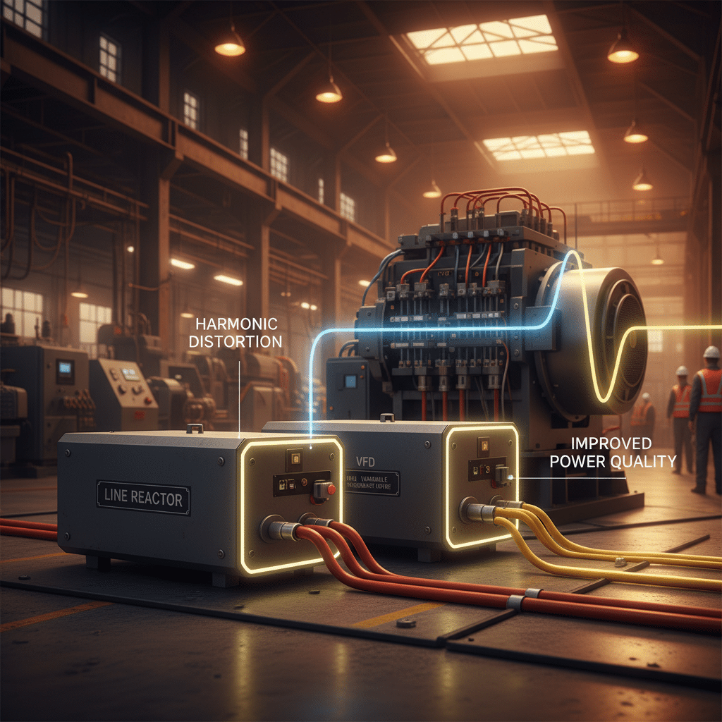
A VFD harmonic filter is crucial for mitigating electrical noise. This diagram illustrates how adding a line reactor to a VFD smooths the electrical waveform, ensuring cleaner power.
Installation Guide: Connecting Your VFD Input Protection
Properly installing a vfd input reactor is fundamental to safeguarding your equipment. Before beginning, always adhere to strict lockout/tagout (LOTO) procedures to ensure the circuit is de-energized and safe to work on. The primary goal is to correctly wire the 3 phase line reactor in series between the main power disconnect and the Variable Frequency Drive (VFD) input terminals. This configuration allows the reactor to buffer the VFD from transient overvoltages and other line disturbances, a key benefit described by sources like Eaton Line Reactors. Consequently, this simple addition can significantly improve the reliability and lifespan of the drive.
Mounting and Wiring Your VFD Input Reactor
Physical placement of the reactor is an important consideration. For optimal performance and safety, the unit should be mounted as close as practical to the VFD, which minimizes the length of unprotected wiring between the two devices as noted in guidance from Rae. Ensure adequate ventilation around the reactor, as it will generate heat during operation. The wiring path is straightforward: connect the incoming power conductors (L1, L2, L3) to the reactor’s input terminals and then run a second set of conductors from the reactor’s output terminals to the corresponding R/L1, S/L2, and T/L3 terminals on the VFD. The added impedance is what provides crucial protection against surges, as detailed by eaton.com.
Finally, pay close attention to conductor sizing and terminal connections. All wiring must be sized according to the VFD’s full-load amperage (FLA) rating and comply with the National Electrical Code (NEC) or applicable local standards. Use properly crimped lugs for all connections and torque the terminal screws to the manufacturer’s specifications to prevent overheating and ensure a secure, low-resistance connection. In addition to the power conductors, a solid grounding connection between the reactor chassis, the VFD, and the facility’s earth ground is essential for safety and mitigating electrical noise. Following these installation best practices ensures your line reactor VFD setup operates safely and effectively, as highlighted in technical papers from suppliers like TransCoil Reactor Benefits.
Conclusion: a Small Investment for Major Motor Drive Protection
In conclusion, integrating a vfd input reactor is not merely an optional add-on but a fundamental component for robust system protection. Throughout this article, we have explored how these devices serve as the first line of defense for your valuable Variable Frequency Drive (VFD) and AC Motor assets. While the initial cost may seem like an extra expense, it is incredibly minor when compared to the potential costs of equipment failure, operational downtime, and troubleshooting complex power quality issues. Ultimately, the decision to install a motor drive reactor is a proactive measure that pays significant dividends in reliability and longevity.
Line Reactor VFD: Surge & Harmonic Protection
The evidence overwhelmingly supports the benefits of adding a line reactor, as highlighted by multiple industry sources. By adding impedance, a line reactor effectively absorbs and mitigates a wide range of electrical disturbances. For instance, it provides crucial protection against surges and transient overvoltages, a benefit detailed by Eaton Line Reactors and Transients. Furthermore, this added impedance is instrumental in reducing harmonic distortion, helping to maintain compliance with standards like IEEE 519 and improving overall power quality. As a result, the VFD’s sensitive electronic components are shielded from damaging voltage spikes and polluted power, which, according to EMIS Global Insights, can significantly extend motor life.
Therefore, whether you are commissioning a new VFD system or looking to enhance the reliability of an existing one, installing a line reactor vfd is one of the most cost-effective reliability upgrades you can make. The protection it affords against common line disturbances is essential for ensuring your motor drive systems operate efficiently and without interruption for years to come. As experts from transcoil.com emphasize, this simple device is a proven solution for comprehensive drive protection. Investing in a quality AC line reactor from trusted manufacturers like MTE Corporation, TCI, LLC, or Schaffner Holding AG is a small price to pay for major operational peace of mind.


