 https://www.precision-elec.com/wp-content/uploads/2015/10/lenze-i500.jpg
789
1500
Craig Chamberlin
https://www.precision-elec.com/wp-content/uploads/2025/02/Precision-Electric-Logo-TEXT-ONLY-Color-NEW.png
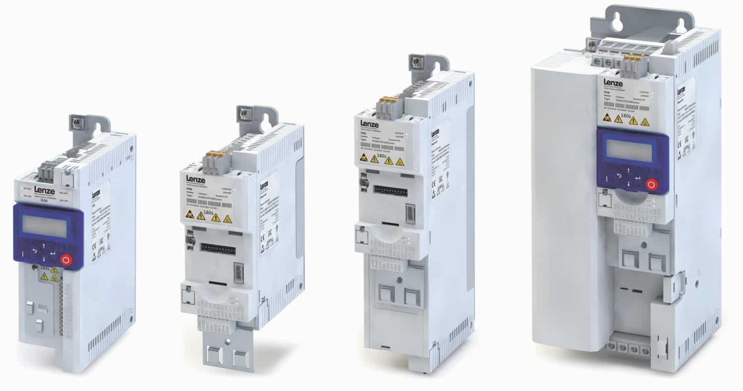
Craig Chamberlin2015-10-30 14:01:482015-10-30 14:03:18Lenze i500
https://www.precision-elec.com/wp-content/uploads/2015/10/lenze-i500.jpg
789
1500
Craig Chamberlin
https://www.precision-elec.com/wp-content/uploads/2025/02/Precision-Electric-Logo-TEXT-ONLY-Color-NEW.png
Craig Chamberlin2015-10-30 14:01:482015-10-30 14:03:18Lenze i500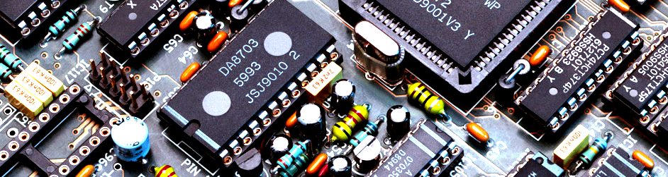 https://www.precision-elec.com/wp-content/uploads/2015/10/inverter-repair-1.jpg
251
942
Craig Chamberlin
https://www.precision-elec.com/wp-content/uploads/2025/02/Precision-Electric-Logo-TEXT-ONLY-Color-NEW.png
Craig Chamberlin2015-10-23 14:09:472015-10-23 14:09:47Inverter Repair
https://www.precision-elec.com/wp-content/uploads/2015/10/inverter-repair-1.jpg
251
942
Craig Chamberlin
https://www.precision-elec.com/wp-content/uploads/2025/02/Precision-Electric-Logo-TEXT-ONLY-Color-NEW.png
Craig Chamberlin2015-10-23 14:09:472015-10-23 14:09:47Inverter Repair https://www.precision-elec.com/wp-content/uploads/2015/10/abb-motor-control-applications.jpg
478
788
Craig Chamberlin
https://www.precision-elec.com/wp-content/uploads/2025/02/Precision-Electric-Logo-TEXT-ONLY-Color-NEW.png
Craig Chamberlin2015-10-16 14:54:532015-10-16 14:54:53ABB Motor Control Applications
https://www.precision-elec.com/wp-content/uploads/2015/10/abb-motor-control-applications.jpg
478
788
Craig Chamberlin
https://www.precision-elec.com/wp-content/uploads/2025/02/Precision-Electric-Logo-TEXT-ONLY-Color-NEW.png
Craig Chamberlin2015-10-16 14:54:532015-10-16 14:54:53ABB Motor Control Applications https://www.precision-elec.com/wp-content/uploads/2015/10/inverter-drives1.jpg
321
791
Craig Chamberlin
https://www.precision-elec.com/wp-content/uploads/2025/02/Precision-Electric-Logo-TEXT-ONLY-Color-NEW.png
Craig Chamberlin2015-10-08 14:33:422015-10-09 06:37:03Inverter Drives
https://www.precision-elec.com/wp-content/uploads/2025/02/Precision-Electric-Logo-TEXT-ONLY-Color-NEW.png
261
1224
Craig Chamberlin
https://www.precision-elec.com/wp-content/uploads/2025/02/Precision-Electric-Logo-TEXT-ONLY-Color-NEW.png
Craig Chamberlin2015-10-02 12:24:082015-10-02 12:24:10ABB ACS355 Emergency Stop
https://www.precision-elec.com/wp-content/uploads/2015/10/inverter-drives1.jpg
321
791
Craig Chamberlin
https://www.precision-elec.com/wp-content/uploads/2025/02/Precision-Electric-Logo-TEXT-ONLY-Color-NEW.png
Craig Chamberlin2015-10-08 14:33:422015-10-09 06:37:03Inverter Drives
https://www.precision-elec.com/wp-content/uploads/2025/02/Precision-Electric-Logo-TEXT-ONLY-Color-NEW.png
261
1224
Craig Chamberlin
https://www.precision-elec.com/wp-content/uploads/2025/02/Precision-Electric-Logo-TEXT-ONLY-Color-NEW.png
Craig Chamberlin2015-10-02 12:24:082015-10-02 12:24:10ABB ACS355 Emergency Stop


