 https://www.precision-elec.com/wp-content/uploads/2014/08/smvector-series-variable-frequency-drive.jpg
442
442
Craig Chamberlin
https://www.precision-elec.com/wp-content/uploads/2025/02/Precision-Electric-Logo-TEXT-ONLY-Color-NEW.png
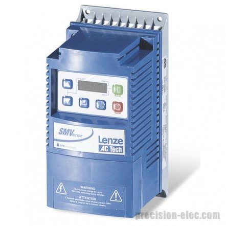
Craig Chamberlin2015-04-16 14:37:402018-02-09 12:15:476 Step Basic Setup Of An SMV Variable Frequency Drive
https://www.precision-elec.com/wp-content/uploads/2014/08/smvector-series-variable-frequency-drive.jpg
442
442
Craig Chamberlin
https://www.precision-elec.com/wp-content/uploads/2025/02/Precision-Electric-Logo-TEXT-ONLY-Color-NEW.png
Craig Chamberlin2015-04-16 14:37:402018-02-09 12:15:476 Step Basic Setup Of An SMV Variable Frequency Drive https://www.precision-elec.com/wp-content/uploads/2015/04/adjustable-speed-drive-repair.jpg
792
1284
Craig Chamberlin
https://www.precision-elec.com/wp-content/uploads/2025/02/Precision-Electric-Logo-TEXT-ONLY-Color-NEW.png
Craig Chamberlin2015-04-16 13:04:412015-07-31 11:41:47Adjustable Speed Drive Repair
https://www.precision-elec.com/wp-content/uploads/2015/04/adjustable-speed-drive-repair.jpg
792
1284
Craig Chamberlin
https://www.precision-elec.com/wp-content/uploads/2025/02/Precision-Electric-Logo-TEXT-ONLY-Color-NEW.png
Craig Chamberlin2015-04-16 13:04:412015-07-31 11:41:47Adjustable Speed Drive Repair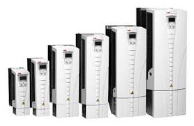 https://www.precision-elec.com/wp-content/uploads/2015/04/acs550.jpg
181
278
Craig Chamberlin
https://www.precision-elec.com/wp-content/uploads/2025/02/Precision-Electric-Logo-TEXT-ONLY-Color-NEW.png
Craig Chamberlin2015-04-14 14:31:192018-04-20 18:05:16Precision Electric Now Supplies ABB ACS550 Series Drives
https://www.precision-elec.com/wp-content/uploads/2015/04/acs550.jpg
181
278
Craig Chamberlin
https://www.precision-elec.com/wp-content/uploads/2025/02/Precision-Electric-Logo-TEXT-ONLY-Color-NEW.png
Craig Chamberlin2015-04-14 14:31:192018-04-20 18:05:16Precision Electric Now Supplies ABB ACS550 Series Drives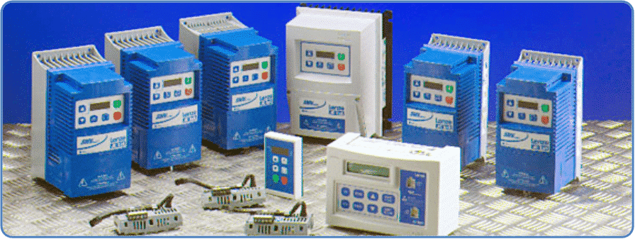 https://www.precision-elec.com/wp-content/uploads/2015/04/SMVector.png
337
896
Craig Chamberlin
https://www.precision-elec.com/wp-content/uploads/2025/02/Precision-Electric-Logo-TEXT-ONLY-Color-NEW.png
Craig Chamberlin2015-04-14 13:46:392018-04-23 13:17:57How To Run A 3 Phase Motor On Single Phase Power
https://www.precision-elec.com/wp-content/uploads/2015/04/SMVector.png
337
896
Craig Chamberlin
https://www.precision-elec.com/wp-content/uploads/2025/02/Precision-Electric-Logo-TEXT-ONLY-Color-NEW.png
Craig Chamberlin2015-04-14 13:46:392018-04-23 13:17:57How To Run A 3 Phase Motor On Single Phase Power


