








Motor Three Phase Guide: Wiring, Nameplate, Reversing and VFDs
When you feed a motor three phase power, you need the right connections, the right protection and a plan for faults. This guide explains how a three-phase electric motor works and how to read its nameplate, wire it and reverse it. Also, you will learn why two-phase running burns motors, when to add a VFD and what a 10 hp motor needs.
On this page
- What is a three-phase motor?
- How does a three-phase motor work?
- Read the nameplate and lead numbers before you wire
- How to wire a three-phase motor
- Before you start: isolate, verify voltage, pick the diagram
- 3-lead and 6-lead motors
- 9-lead dual-voltage motors (230 V and 460 V)
- 12-lead and wye-delta start motors
- How do you wire an IEC or 50 Hz motor?
- Can a 60 Hz motor run on 50 Hz?
- How do you wire and start a wye-delta or soft-starter setup?
- Check rotation and tighten up
- How to reverse the rotation of a three-phase motor
- Can a three-phase motor run on two phases?
- Using a VFD for a three-phase motor
- 10 hp three-phase motor: current, wire and protection
- Conductor ampacity: the 125% rule
- What wire size and insulation column apply at 208, 230 and 460 V?
- Short-circuit, ground-fault and overload protection
- How do you pick and set the overload relay?
- How do you size the starter, contactor and disconnect?
- What equipment grounding conductor and bonding does the motor circuit need?
- Why is 460 V preferred over 230 V for a 10 hp motor?
- Speed, frame and torque for a 10 hp motor
- Common mistakes when wiring and running three-phase motors
- When to repair, rewind or replace, and when to call for help
- Where to find manuals, wiring diagrams and code references
- Frequently asked questions
What is a three-phase motor?
A three-phase motor is an AC motor powered by three alternating currents. Each current peaks 120 electrical degrees after the one before it. So when you give a motor three phase current, it gets a smooth, steady push instead of the pulsing power of a single phase. That is why most industrial motors are three-phase.
Plants also choose a 3 phase motor because it is robust and easy to maintain. For example, a squirrel-cage design has no brushes to wear out. In addition, it draws less current for the same work. A 10 hp three phase motor draws 28 A at 230 V, while a 10 hp single-phase motor draws 50 A.
This guide follows the order you work in on any motor three phase job. Use this map to jump to the part you need:
- How it works: the rotating field, synchronous speed, slip and direction.
- Nameplate and leads: lead counts, numbering and dual-voltage logic.
- Wiring: 3, 6, 9 and 12-lead connections, IEC motors and wye-delta starting.
- Reversing: where and how to swap leads.
- Two-phase operation: why it fails, how to protect against it and how to test after a trip.
- VFDs: what a drive adds and how to size and install one.
- 10 hp sizing: full-load current, wire size, overloads, starter, disconnect and grounding.
- Repair and references: repair, rewind or replace, common mistakes and where to find diagrams.
Types of AC three-phase motor
What is an AC motor three phase design, and what types are there? It is any AC motor built to run from a three-phase supply. There are two main types: induction and synchronous. Also, most motor three phase installations in plants use induction motors.
A three phase induction motor comes in two rotor styles. First, a squirrel-cage rotor has bars shorted together at each end. Second, a wound rotor has its own windings, brought out through slip rings. NEC Table 430.250, the code table for motor current, covers both styles.
The key difference between induction and synchronous motors is speed. An induction rotor always turns a little slower than the rotating field, and that gap is slip. However, a synchronous rotor locks to the field and turns at exactly its speed. So most of this guide covers induction motors, because they run most plant equipment.
How does a three-phase motor work?
A 3-phase AC motor turns electrical energy into torque without any wired connection to a squirrel-cage rotor. Instead, the stator does the work through magnetism. Here is the sequence, from supply to shaft:
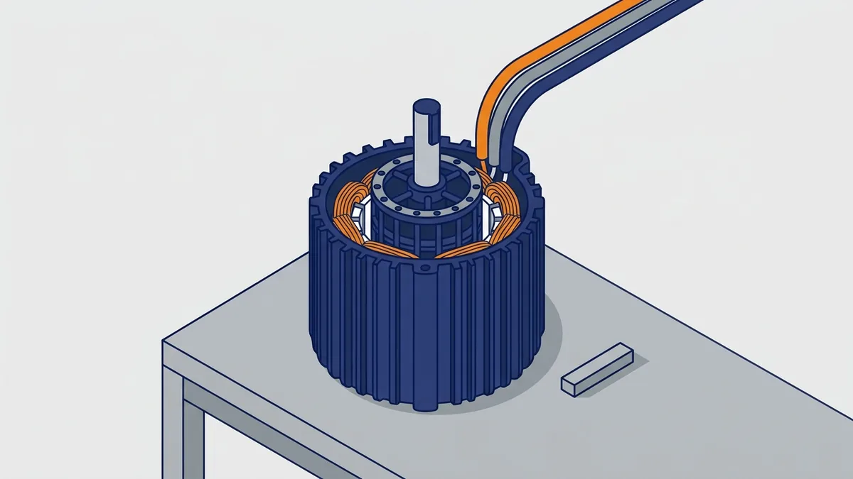
- Three sets of stator windings sit 120° apart around the inside of the frame.
- The supply sends three currents, 120° apart in time, through those windings.
- Together, the three currents make one magnetic field that rotates around the stator.
- That rotating field cuts across the rotor conductors and induces current in them.
- The rotor current makes its own field, which interacts with the stator field and makes torque.
In short, you feed the motor three phase power, and the rotating field drags the rotor along. That idea sits at the core of every motor three phase design. The next three sections explain the field, the speed and the direction in more detail.
The rotating magnetic field
How does a three-phase motor make a rotating magnetic field? First, balanced currents flow in windings spaced 120° apart. Each current rises and falls in turn, so the strongest point of the field moves from one winding to the next. As a result, the combined field keeps a constant strength and spins around the stator.
That constant strength matters. The combined field is about 1.5 times the peak flux of one phase alone, and it does not pulse. So the motor three phase field gives even torque through every turn of the shaft.
Next, the spinning field sweeps past the rotor conductors. By Faraday’s law, that motion induces current in the rotor. Then the rotor current builds its own magnetic field. Finally, that field interacts with the stator field and pushes the rotor in the same direction the field turns.
Synchronous speed, slip and RPM
Synchronous speed is the speed of the rotating field. You find it with this formula: Ns = 120 × f ÷ P. Here, f is the supply frequency in hertz and P is the number of poles. For example, a 4-pole motor on 60 Hz has a field speed of 120 × 60 ÷ 4, or 1800 rpm.
| Poles | Synchronous speed at 60 Hz |
|---|---|
| 2 | 3600 rpm |
| 4 | 1800 rpm |
| 6 | 1200 rpm |
| 8 | 900 rpm |
Slip is the gap between synchronous speed and actual rotor speed, shown as a percent of synchronous speed. The rotor can never reach field speed. If it did, the field would no longer cut the rotor bars. Then there would be no induced current and no torque.
At full load, slip is typically about 2 to 5%. So to find the real rpm, read the speed on the nameplate, since every motor three phase design runs a bit below synchronous speed. For instance, a 4-pole motor shows a full-load speed a little under 1800 rpm. For step-by-step examples, see our separate post on calculating motor RPM.
Why swapping two leads reverses the motor
Why does swapping two leads reverse a three-phase motor? A three-phase system has only two possible phase sequences. You can think of them as L1-L2-L3 and L1-L3-L2. Also, the rotating field always turns in the direction that sequence sets.
When you swap any two supply lines, you flip the sequence. As a result, the field reverses, and the rotor follows it. However, moving all three lines over one position keeps the same sequence, so the direction stays the same. That rule works for every motor three phase connection, whether wye or delta.
Read the nameplate and lead numbers before you wire
Is the motor three phase, and what voltage does it need? The nameplate answers both questions. It also shows how to connect the leads, so read it before you open the terminal box.
How to read a three-phase motor nameplate
Check these items first on any 3ph motor nameplate:
- Phase and frequency: confirm it says three phase and matches your supply frequency, such as 60 Hz.
- Voltage: one value, or two values such as 230/460 V on a dual-voltage motor.
- Full-load amps (FLA): the current the motor draws at rated load. You set overloads from this value.
- Connection diagram: look for the Y (wye) or delta symbol next to each voltage.
- Speed: the full-load rpm, which tells you the pole count.
- Frame: the standard mounting size, which helps you match a replacement.
- Insulation class: the temperature rating of the winding insulation.
Next, compare the lead numbers in the diagram with the tags on the leads in the terminal box. They must match. If they do not, stop and identify the leads before you connect anything.
How many leads does a three-phase motor have?
Motor three phase lead counts follow a few standard patterns. The count tells you whether the motor runs on one voltage or two. Use this table to read what each count means.
| Leads | Voltage design | What you do in the field | Typical use |
|---|---|---|---|
| 3 | Single voltage | Land L1, L2, L3 on T1, T2, T3 | Simple motors with the connection made inside |
| 6 | Single voltage, or wye-delta start | Make the wye or delta connection, or wire to a wye-delta starter | General use and reduced-voltage starting |
| 9 | Dual voltage (such as 230/460 V) | Connect T4 to T9 for high or low voltage | The most common dual-voltage motor in plants and shops |
| 12 | Dual voltage, wye or delta, series or parallel | Choose from more connection options | Large motors and dual-voltage wye-delta start |
What do the numbers mean? NEMA motors mark the leads T1 through T9, plus T10 to T12 on 12-lead motors. In contrast, IEC motors use U, V and W for the main terminals. Also, a dual-voltage winding has 12 lead ends in all, so a 9-lead motor connects the rest inside.
How dual-voltage leads work
A dual-voltage motor splits each phase winding into two halves. For the high voltage, you connect the halves in series. For the low voltage, you connect them in parallel. That way, each half sees the same voltage on either supply.
So a 230/460 V motor runs on either voltage only because of how you connect T4 through T9. The windings themselves do not change. Instead, only the lead connections in the terminal box change.
Identify leads with an ohmmeter
If the diagram or lead tags are missing, an ohmmeter can help. First, lock out the power and disconnect all leads from the supply. Then check continuity between every pair of leads and write down the groups.
On a delta-wound 9-lead motor, T1 should show continuity to T4 and T9. Likewise, T2 should connect to T5 and T7, and T3 to T6 and T8. On a wye-wound 9-lead motor, you will find three pairs (T1-T4, T2-T5, T3-T6) and one group of three (T7, T8, T9).
However, a meter finds winding groups, not always the exact numbers. So always confirm your result against the nameplate diagram. If the numbers still do not add up, have the motor checked before you run it.
How to wire a three-phase motor
How do you wire up a three-phase motor? The steps are the same whether you call it a 3 phase motor or a three-phase electric motor. Also, good motor three phase wiring always starts with the nameplate. Here is the full process in order:
- Lock out the supply and verify it is dead.
- Confirm the supply voltage and pick the matching diagram.
- Check the lead numbers against the diagram.
- Connect L1, L2 and L3 and any joined leads as the diagram shows.
- Insulate and secure every connection, and connect the equipment ground.
- Check every connection again, then test rotation.
The sections below cover how to wire a three phase electric motor for each lead count. In every case, follow the nameplate diagram over any general table, including the ones here.
Before you start: isolate, verify voltage, pick the diagram
First, lock out and tag out the disconnect. Then test the motor leads with a meter you have proven on a live source. Never trust a switch position alone.
Next, confirm the supply voltage at the disconnect. In North America, common three-phase supplies are 208, 230, 460 and 575 V. Then match the motor connection to that voltage. Many guides skip this step, yet a wrong match can ruin a motor fast.
For example, if you wire the low-voltage connection on a 460 V supply, each winding half sees about double its rated voltage. As a result, the motor overheats and can fail on the first start. So never feed the motor three phase power until the connection matches the supply. Finally, check the lead tags one more time.
3-lead and 6-lead motors
A 3-lead motor is the simplest. The manufacturer has already made the wye or delta connection inside, so you only land the lines. Connect L1 to T1, L2 to T2 and L3 to T3.
A 6-lead single-voltage motor brings out both ends of each winding. For a delta connection, tie T1 to T6, T2 to T4 and T3 to T5. Then land L1, L2 and L3 on those three pairs. For a wye connection, join T4, T5 and T6, and land the lines on T1, T2 and T3.
Makers design some 6-lead motors for wye-delta starting. In that case, the starter makes the wye and delta connections, so follow the starter documentation. Also, check the nameplate, because it tells you which connection the motor needs.
9-lead dual-voltage motors (230 V and 460 V)
How do you wire a three-phase motor for 230 V or 460 V? The 9-lead motor is the most common dual-voltage type in plants and shops. Use the table below, then check your motor three phase connections against the nameplate diagram.
| Connection | L1 | L2 | L3 | Join together |
|---|---|---|---|---|
| High voltage (460 V), wye or delta | 1 | 2 | 3 | 4-7, 5-8, 6-9 |
| Low voltage (230 V), wye | 1, 7 | 2, 8 | 3, 9 | 4-5-6 |
| Low voltage (230 V), delta | 1, 6, 7 | 2, 4, 8 | 3, 5, 9 | None |
For example, a 230/460 V motor on a 460 V supply uses the high-voltage row. You join 4-7, 5-8 and 6-9, then land L1, L2 and L3 on leads 1, 2 and 3. On a 230 V supply, you use the low-voltage row that matches the motor’s winding.
Keep in mind that the manufacturer fixes the wye or delta winding inside the motor. In the field, you only choose high or low voltage. Also, wire colors and diagrams differ by manufacturer, so the nameplate diagram always has the final say.
12-lead and wye-delta start motors
How do you wire a three-phase electric motor with 3, 6 or 12 leads? You will find the 3 and 6-lead connections above. A 12-lead motor gives the most options, because you can connect it in wye or delta, and in series or parallel. So larger motors often use 12 leads.
For example, the 12-lead wye low-voltage (230 V) connection works like this:
- L1 to T1 and T7
- L2 to T2 and T8
- L3 to T3 and T9
- Join T4, T5, T6, T10, T11 and T12 together
Dual-voltage wye-delta start motors use all 12 leads. The starter connects the windings in wye to start, then switches them to delta to run. So for start and run wiring, follow the wye-delta starter documentation and the motor diagram together.
How do you wire an IEC or 50 Hz motor?
IEC motors use different markings, but the wiring logic is the same. The main terminals U1, V1 and W1 match T1, T2 and T3 on a NEMA motor. On a 6-terminal IEC motor, the other ends are W2, U2 and V2, which play the role of T4, T5 and T6.
Supplies also differ. Many 50 Hz regions use 380 V or 400 V. A common IEC nameplate reads 230/400 V. That motor runs in delta on 230 V and in wye on 400 V. In both cases, each winding sees the same voltage. So as always, match the connection to the measured supply and follow the nameplate.
Can a 60 Hz motor run on 50 Hz?
Sometimes, but not by just plugging it in. A winding needs the voltage to scale with frequency, so a lower frequency needs a lower voltage. For example, a 460 V, 60 Hz motor can run on about 380 V at 50 Hz. However, it turns about one sixth slower, because synchronous speed drops with frequency.
Running the same motor at full voltage on 50 Hz overheats it. So check the nameplate for dual 50/60 Hz ratings first. If it has none, ask the maker or our shop before you connect it.
How do you wire and start a wye-delta or soft-starter setup?
A wye-delta starter uses three contactors: main, star (wye) and delta. It also uses a timer and an interlock so the star and delta contactors never close together. The motor needs six leads, and its delta connection must match your supply voltage. First the main and star contactors close, and the motor starts in wye. Then the timer opens the star contactor and closes the delta contactor.
In wye, the motor sees about 58% of line voltage. As a result, starting current falls to about one third of the direct-on-line value, and starting torque falls by about the same amount. Direct-on-line starting often draws about six times full-load current. So wye-delta suits loads that start light, such as fans and unloaded pumps.
Set the timer so the motor is near full speed before the switch. That time depends on the load, so watch the current during a test start. For contactor sizing, the main and delta contactors carry about 58% of motor line current, because they sit in the winding path. The star contactor carries less. Still, follow the starter maker’s selection chart.
A soft starter works differently. You wire line power to its input and the motor to its output, then set the ramp time and starting voltage or current limit. Many also use a bypass contactor after the ramp. Set these from the soft starter manual and the load.
Check rotation and tighten up
How do you check rotation after wiring? First, check every connection against the diagram before you close the terminal box. Then make sure each joint is tight and insulated and that no bare conductor touches the box.
Next, confirm direction. A phase rotation meter checks the sequence of the motor three phase supply before start. Or you can briefly jog the motor and watch the driven load. If the wrong direction can cause damage, uncouple the load or check it first, as with pumps, fans and gearboxes.
If the motor turns the wrong way, lock out and swap two supply lines. The next section explains where to make that swap.
How to reverse the rotation of a three-phase motor
How do you reverse the rotation of a three-phase motor? Reversing the motor three phase sequence takes one swap. First, lock out the power. Then swap any two of the L1, L2 and L3 supply connections, usually L1 and L3 on the line side of the starter.
Make the swap at the starter, contactor or terminal strip. Do not swap leads inside the terminal box of a motor that is connected for a specific voltage. Otherwise, you can break the high or low-voltage connection and damage the windings.
Pick the right reversing method
Your method depends on how the motor starts and how often you reverse it:
- One-time fix: swap two supply lines at the starter, as above.
- Regular reversing: use a forward/reverse starter with two three-pole contactors. Each contactor gives a different phase sequence, and an interlock stops both from closing together.
- Wye-delta start: swap two incoming supply phases. Or swap the matching leads on both the star and delta contactor groups.
- VFD-driven motor: change the direction in the drive settings instead of rewiring.
Can a three-phase motor run on two phases?
Can a three-phase motor run on two phases? It is not designed to, and you should not let it. A running motor may keep turning after it loses one phase, which is called single phasing. However, it overheats and can burn out.
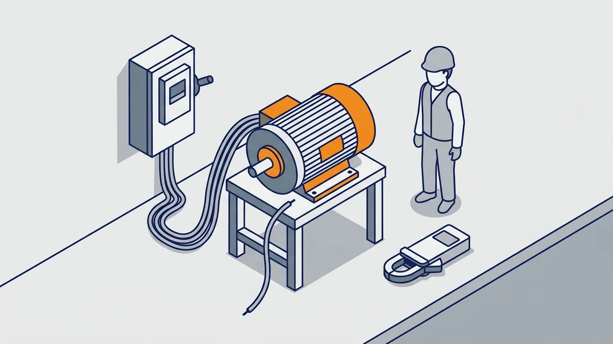
A stopped motor on two phases may not start at all. Or it may start and draw heavy current. Either way, two-phase running is harmful, because the motor can stall, hum and heat up quickly.
What happens when a motor loses a phase
When you lose one leg of the motor three phase supply, current in the remaining windings rises sharply. Published figures for that rise differ, so do not count on any single number. Also, torque becomes uneven, so you will often hear noise and feel vibration.
A loaded motor may slow down and stall. Meanwhile, it keeps trying to drive the load until it fails or a protective device takes it off the line. Damage can happen in minutes to hours, depending on load. Without proper overload or fuse protection, the motor can burn.
Single phasing is not the same as phase imbalance. With imbalance, all three phases are present but unequal. In contrast, single phasing is the complete loss of one phase, and it is a far more severe, faster-acting fault.
Common causes of single phasing
- One blown fuse in a three-fuse disconnect
- An open or burnt contactor pole
- Loose or corroded terminals
- A broken conductor
- Faults on the utility side of the service
How to protect against single phasing
How do you protect a three-phase motor from phase loss? First, know the limits of a standard overload. A bimetallic thermal overload relay does not give reliable single-phasing protection. Also, across-the-line starters and contactors have no built-in phase-loss protection.
So good motor three phase protection watches all three lines. An electronic overload relay or a phase-loss relay monitors each phase and trips the motor when one drops out. Some models detect phase loss within 1 to 3 seconds. In addition, a VFD detects phase loss automatically.
After a phase-loss trip, do not just reset and restart. First, find and fix the cause. Then test the motor, including winding resistance and an insulation test, before you put it back in service.
What readings are acceptable after a phase-loss trip?
First, lock out the power and disconnect the motor leads from the starter or drive. Then run two tests.
- Winding resistance: use a low-resistance ohmmeter, since a normal meter is too coarse. The three phase readings should match each other within a few percent, and they should match the maker’s data if you have it. A 10 hp motor reads only a small fraction of an ohm to a few ohms, so the balance matters more than the number.
- Insulation resistance: use a megger at 500 V DC on a motor under 1000 V. Test each lead to the frame. IEEE 43 sets a minimum of 5 megohms for most random-wound motors, and many shops treat 1 megohm as the hard floor. Higher is better, and a falling trend over time is a warning.
If readings are unbalanced or low, do not restart the motor. A damp motor may recover after drying, but a motor with shorted turns needs a shop check. Bring the readings with you, because they speed up the diagnosis.
If you only have single-phase power
What if you only have single-phase power? A single-phase supply cannot give a motor three phase power on its own, so you need a drive or a phase converter. Do not try to run the motor on two lines of a single-phase service.
We cover this in separate posts. See our guide to running a 3-phase motor on single-phase power and our overview of single-phase to three-phase solutions. Also, read our post on using an SMV drive to run a three-phase motor from a single-phase supply.
Using a VFD for a three-phase motor
A drive adds control that a starter cannot give. However, you do not need one just to run a motor. This section covers what a drive does and the basics of hooking one up.
How a VFD controls motor speed
What is a VFD for three phase motor control, and how does it change speed? A variable frequency drive (VFD) varies the frequency and voltage it sends to the motor. Because synchronous speed equals 120 × f ÷ P, a lower frequency gives a slower field. As a result, the motor speed follows the field.
So the drive gives the motor three phase power at whatever frequency you set. This adds soft starting and smooth speed control. In addition, the drive detects phase loss on its own.
Still, a three-phase motor runs directly from a three-phase supply through a starter. So add a drive only when you need speed control, soft starting or another drive feature.
Wiring and sizing the drive
You wire the motor to the drive’s output terminals, usually marked U, V and W. Never connect line power to those terminals. Also, wire the motor for the voltage the drive puts out, not the voltage feeding the drive.
Next, enter the motor’s nameplate FLA in the drive to set its motor overload. Size the drive to the motor’s full-load current, not horsepower alone. Finally, check the drive manual for cable length limits and motor-lead requirements before you install.
For full detail, see our separate posts on how to choose a VFD and how to wire a VFD step by step.
How do you size and install a VFD for a 10 hp motor?
Start with the drive’s rated output current. It must be at least the motor’s nameplate FLA. Choose a larger drive for heavy loads or high starting torque. Then size the input side from the drive’s input current rating, not the motor’s. NEC 430.122 sets the input conductor minimum at 125% of the drive’s rated input current. Use the fuse or breaker type and size in the drive manual.
On the output side, long cable runs cause voltage spikes at the motor. The safe length depends on the drive, the cable and the motor, so use the drive manual. When runs are long, add an output reactor or a dV/dt filter. An input line reactor also helps on weak or noisy supplies.
A 460 V drive puts more stress on motor insulation than a 230 V drive. So pick an inverter-duty motor, which NEMA MG 1 Part 31 covers, for 460 V use, long leads or slow-speed running. Also remember that a fan-cooled motor loses cooling at low speed. Follow the drive manual for grounding and for any shielded cable it requires.
10 hp three-phase motor: current, wire and protection
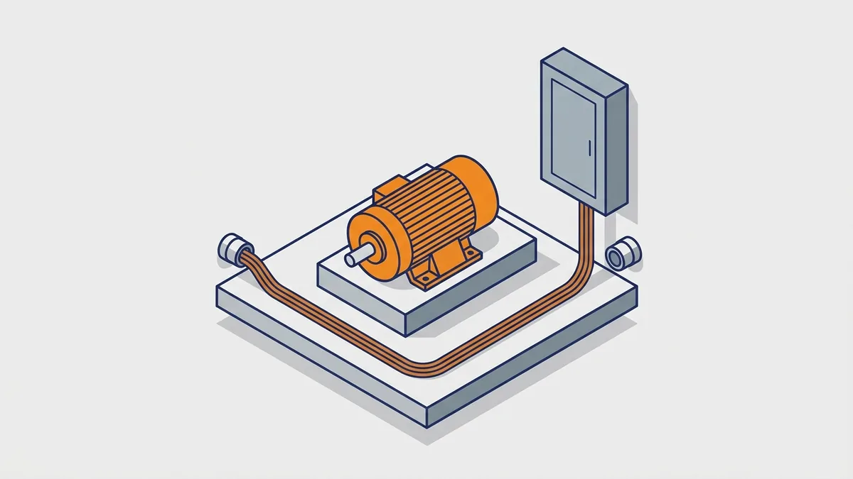
What full-load current and wire size does a 10 hp three-phase motor need? Start with NEC Table 430.250, not the nameplate. That table gives these full-load currents for a standard 10 hp motor three phase circuit:
| Supply voltage | Table 430.250 full-load current | Minimum conductor ampacity (125%) |
|---|---|---|
| 208 V | 30.8 A | 38.5 A |
| 230 V | 28 A | 35 A |
| 460 V | 14 A | 17.5 A |
| 575 V | 11 A | 13.75 A |
The table values are nominal figures for standard Design B motors. So check the actual nameplate too, especially on high-efficiency or Design E motors. Also, the table has no 380 V or 400 V rows. It lists 115, 200, 208, 230, 460, 575 and 2300 V.
Conductor ampacity: the 125% rule
NEC 430.22 sets the minimum ampacity for branch-circuit conductors. For a single continuous-duty motor, the conductors need at least 125% of the table current. For example, a 10 hp motor at 460 V needs 14 × 1.25 = 17.5 A minimum.
What wire size and insulation column apply at 208, 230 and 460 V?
You pick the conductor from NEC Table 310.16. The column you use depends on the temperature rating of the terminals. For circuits of 100 A or less, NEC 110.14(C) sends you to the 60°C column unless the equipment is marked for 75°C. Many modern motors and starters are marked 75°C, so check the labels. The table shows copper conductors with the ampacities from Table 310.16.
| Supply voltage | Minimum ampacity | Copper, 60°C column | Copper, 75°C column |
|---|---|---|---|
| 208 V | 38.5 A | 8 AWG (40 A) | 8 AWG (50 A) |
| 230 V | 35 A | 8 AWG (40 A) | 10 AWG (35 A) |
| 460 V | 17.5 A | 12 AWG (20 A) | 12 AWG (25 A) |
These are minimums. Hot ambient temperatures, more than three current-carrying conductors in one conduit and long runs can call for a larger wire. Voltage drop is another reason to go up a size. Also confirm the sizes against the code edition your local authority has adopted.
Short-circuit, ground-fault and overload protection
You size short-circuit and ground-fault protection from the table current under NEC 430.52. For an inverse-time breaker, the maximum is 250% of the table value. Check the code for other device types and any exceptions.
Overload protection works differently. Under NEC 430.32, you set it from the nameplate FLA, not the table. NEC 430.6(A) tells you which value applies where. In short, the table governs conductors and short-circuit protection, while the nameplate governs overloads.
How do you pick and set the overload relay?
Take the nameplate FLA and apply NEC 430.32. If the motor has a service factor of 1.15 or more, or a temperature rise of 40°C or less, the overload trips at no more than 125% of FLA. For other motors, the limit is 115% of FLA. Many overloads have a dial, so set it to the nameplate FLA first and adjust only within those limits if nuisance trips occur.
Next, choose the trip class. Class 10 is the usual choice for standard loads and trips faster. Class 20 gives more time for hard-to-start loads, such as high-inertia fans. Class 30 is for very long starts. Pick the lowest class that rides through a normal start.
How do you size the starter, contactor and disconnect?
For starters, NEMA sizes follow horsepower and voltage. A 10 hp motor at 208 or 230 V needs a NEMA size 2 starter. At 460 V, a NEMA size 1 starter covers 10 hp. Always check the maker’s rating chart, since IEC contactors use amp ratings instead.
For the disconnect, NEC 430.110 says the rating must be at least 115% of the table current, and NEC 430.109 allows a horsepower-rated switch. For 10 hp, that works out to about 32 A at 230 V, 35 A at 208 V and 16 A at 460 V. So a 60 A switch fits 208 and 230 V, and a 30 A switch fits 460 V. Then confirm the horsepower rating on the switch label.
What equipment grounding conductor and bonding does the motor circuit need?
You size the equipment grounding conductor from the rating of the overcurrent device ahead of the motor, using NEC Table 250.122. For copper, a 60 A device needs 10 AWG, and a device from 61 to 100 A needs 8 AWG. Larger conductors are needed if you upsize the phase conductors for voltage drop. Check the code for the exact rule.
Next, land the grounding conductor on the motor’s ground terminal in the terminal box. If you use metal conduit, keep every fitting tight, because the conduit is part of the ground path. On a VFD circuit, ground both the drive and the motor, and follow the drive manual for bonding of shielded cable.
Why is 460 V preferred over 230 V for a 10 hp motor?
Why do plants run 10 hp motors at 460 V instead of 230 V? The table current at 460 V is 14 A, half the 28 A at 230 V. Lower current allows smaller conductors. As a result, many commercial and industrial motor feeders run at 460 V.
The same logic explains why 10 hp is normally three-phase. A 10 hp single-phase motor at 230 V draws 50 A under Table 430.248. That is nearly twice the 28 A of a 10 hp three-phase motor at the same voltage.
Speed, frame and torque for a 10 hp motor
A 10 hp motor’s speed depends on its pole count. At 60 Hz, a 2-pole motor has a synchronous speed of 3600 rpm, and a 4-pole motor has 1800 rpm. Similarly, a 6-pole motor has 1200 rpm and an 8-pole motor has 900 rpm. Actual full-load speed is a little lower because of slip.
However, frame size, torque and efficiency vary by design and maker. So read them from the nameplate and the manufacturer’s catalog. You can also check NEMA MG 1, the main NEMA motor standard.
Common mistakes when wiring and running three-phase motors
What are common mistakes when wiring and running a three-phase motor? These six cause a lot of avoidable damage:
- Wrong voltage connection: a 230 V connection on a 460 V supply, or the reverse. Always match the connection to the measured supply.
- Wrong diagram: mixing up lead numbers, or using a diagram from a different motor.
- Swapping leads in the motor box: this can break the voltage connection. Swap at the starter instead.
- Mixing up table and nameplate values: conductors and short-circuit protection use the table, while overloads use the nameplate.
- Trusting a bimetallic overload for phase loss: use an electronic overload or phase-loss relay instead.
- Skipping the rotation check: a pump or gearbox turning backward can damage itself fast.
Most of these mistakes take only seconds to avoid. So check the nameplate twice before you feed the motor three phase power.
When to repair, rewind or replace, and when to call for help
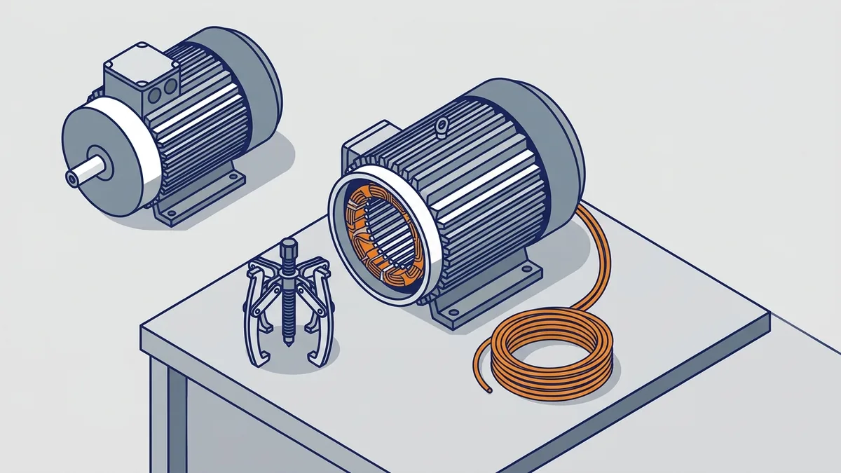
When should you repair, rewind or replace a three-phase motor, and when should you call for help? Start by knowing the warning signs. Then decide based on the motor’s size, age and the cause of the fault.
Signs your three-phase motor needs attention
Watch for these signs on any motor three phase installation:
- It trips on overload again and again.
- It hums but will not turn.
- Windings or the frame run hotter than normal.
- You smell burnt insulation.
- Noise or vibration has increased.
- Insulation resistance reads low after a phase-loss or overheating event.
Do not keep restarting a motor that hums and will not turn. Each attempt draws heavy current and heats the windings further. Instead, lock it out and find the cause.
Repair, rewind or replace?
The right choice depends on the motor’s size, age and condition, and on what failed. Larger motors and special designs are often worth repairing or rewinding. On the other hand, small, standard motors are often simpler to replace. A shop evaluation tells you what failed and which option makes sense.
A common rule of thumb is to replace the motor when the repair quote reaches about 50 to 60% of the cost of a new one. Efficiency matters too. A quality rewind, done to a standard such as ANSI/EASA AR100, can keep the motor’s efficiency close to its original level. A poor rewind can lower it. A new premium-efficiency motor may save energy on a motor that runs many hours a year. The break-even point varies with the motor’s size, running hours and your power cost, so we do not give one horsepower cutoff.
Precision Electric can test a failed motor and help you decide between repair, rewind and replacement. Bring the nameplate details and a short history of the failure, because both speed up the evaluation.
How do you read the nameplate for a replacement motor?
Match these items to the old motor:
- Horsepower, speed and voltage: keep the same hp, rpm and voltage rating.
- Frame size: the frame code sets the mounting footprint and shaft height. Matching it avoids new bases and couplings.
- Service factor: choose the same or higher, because it affects how you set the overload.
- Efficiency: compare the nominal efficiency printed on the nameplate or in the catalog.
- Enclosure and insulation class: keep the same enclosure type for dust, water or hazardous areas.
When to call an electrician or the shop
- You cannot find or read the nameplate diagram.
- Lead numbers do not match the diagram.
- The motor tripped on phase loss.
- Your supply voltage does not match the nameplate.
Where to find manuals, wiring diagrams and code references
Where do you find wiring diagrams, manuals and the NEC table for your motor? For motor three phase wiring diagrams, start with the nameplate diagram and the motor manufacturer’s manual. Together, they are the final word on lead connections for that motor.
For VFD wiring, use the drive manufacturer’s manual. It covers the terminals, settings, cable limits and motor-lead requirements for that drive.
For full-load current and sizing rules, use NFPA 70, the National Electrical Code (NEC). Table 430.250 and sections 430.22, 430.32 and 430.52 sit in Article 430. Also, confirm which edition your local authority has adopted, because the edition in force governs your job. For motor design standards, NEMA MG 1 is the reference.
Frequently asked questions
How do you wire a three-phase motor?
Lock out the supply, confirm its voltage and connect L1, L2 and L3 as the nameplate diagram shows. For a 9-lead motor on high voltage, join 4-7, 5-8 and 6-9, and land L1, L2 and L3 on 1, 2 and 3. For low voltage, use the wye or delta low-voltage row in the table above. Finally, check rotation, and swap any two supply lines if it turns the wrong way.
How does a three-phase motor work?
Three currents 120° apart in the stator windings create a rotating magnetic field. That field induces current in the rotor, and the rotor’s own field interacts with it to make torque. The rotor always runs a little slower than the field, and this gap is slip. The field speed equals 120 × frequency ÷ poles.
Can a three-phase motor run on two phases?
It is not designed to, and you should not rely on it. A running motor can keep turning on two phases, but current in the remaining windings rises sharply and the motor overheats. A stopped motor may not start. So use phase-loss protection, and use a VFD or phase converter to give the motor three phase power from a single-phase supply.
How do you reverse a three-phase motor?
Lock out the power and swap any two of the three supply lines. The usual place is L1 and L3 at the starter. For frequent reversing, use a reversing starter, or change the direction setting in a VFD.
What is the full-load current of a 10 hp three-phase motor?
Per NEC Table 430.250, it is 30.8 A at 208 V, 28 A at 230 V, 14 A at 460 V and 11 A at 575 V. You size conductors at 125% of the table value, so a 460 V motor needs at least 17.5 A of ampacity. You set overload protection from the nameplate FLA.
Do I need a VFD for a three-phase motor?
No. You can feed a motor three phase power directly through a starter. Add a VFD when you need speed control or soft starting, or when you want to run the motor from a drive. A VFD also detects phase loss.
When you feed a motor three phase power and wire it right, you get smooth torque, low current and long service. Read the nameplate first, match the connection to your supply and check rotation before you load the motor. Also, protect it against phase loss, and use the NEC table and nameplate values in the right places.
If you need help with wiring, a motor evaluation, a repair or a quote, contact Precision Electric and our team will help you get your motor running.