








Variable-Speed Drives: How They Work, Sizing and Setup Guide
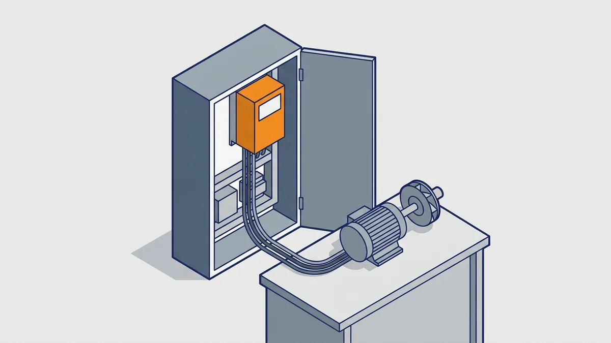
If you maintain, buy or install motors, you will work with variable-speed drives sooner or later. They save energy and match motor speed to the job, but they also bring new settings, wiring rules and fault codes. This guide explains how a drive works, how to choose and size one, how to set it up, and what to do when it fails.
On this page
- What Is a Variable-Speed Drive?
- How Do Variable Frequency Drives Work?
- Types of Variable-Speed Drives
- Variable Frequency Drive Control Methods
- Starting, Stopping and Controlling a VFD
- Why Use a Variable-Speed Drive? Energy and Process Benefits
- Where Variable-Speed Drives Are Used
- How to Select and Size a Variable-Speed Drive
- Allen-Bradley PowerFlex Drives (Rockwell Automation)
- Schneider Electric Altivar Drives
- Installing and Commissioning a VFD
- What are the maximum motor cable lengths, and when do you need a reactor or filter?
- What branch-circuit protection, disconnect and conductors does a drive need?
- Basic start-up sequence
- How do you set overload, minimum speed and cooling for a self-cooled motor at low speed?
- Safety before you open a drive
- How long is the DC bus discharge wait, and what meter or PPE do you need?
- Common VFD Problems and Mistakes
- Maintenance, Repair or Replace a VFD
- Where to Find VFD Manuals, Software and Replacement Drives
- What Does a Variable-Speed Drive Cost?
- Frequently asked questions
What Is a Variable-Speed Drive?
What are variable speed drives?
Variable-speed drives are electronic controllers that set the speed and torque of an AC motor. They do this by changing the frequency and voltage they send to the motor. Without a drive, a motor runs on fixed line power, so it turns at one speed. With a drive, you can run the same motor slow, fast or anywhere in between.
Is a VSD the same as a VFD, an AC drive or an adjustable speed drive?
In everyday use, yes. People call the same box a variable speed drive (VSD), variable frequency drive (VFD), adjustable speed drive (ASD), AC drive, adjustable frequency drive or frequency inverter. For example, Rockwell uses “Adjustable Frequency AC Drive” in its manuals. Strictly speaking, “variable speed drive” is the broader term, because it also covers DC drives.
This guide covers AC drives for induction motors. DC drives use different hardware to control DC motors, so see our post on DC variable speed drives for that topic.
What a drive does besides change speed
A modern drive does much more than set speed. In fact, most variable-speed drives give you these functions:
- Soft start and soft stop: the motor never sees a full-voltage inrush.
- Acceleration and deceleration ramps: you set how many seconds speed changes take.
- Torque and current limits: these protect gearboxes, belts and the product.
- Motor protection: electronic overload replaces or backs up a separate overload relay.
- Process control: a built-in PID loop (a feedback controller) holds pressure, flow or temperature.
- Communications: the drive can report status and take commands from a PLC or network.
How Do Variable Frequency Drives Work?
So how do VFDs work? In short, a VFD turns fixed AC power into DC, then builds new AC at the frequency and voltage the motor needs. It does three jobs in order, with a control board on top. Picture it as this block diagram:
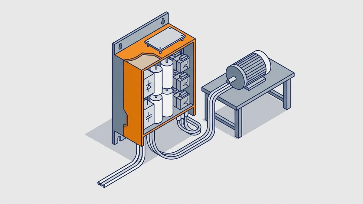
- Rectifier: converts incoming AC to pulsing DC.
- DC bus: smooths the DC and stores some energy in capacitors.
- Inverter: switches the DC to build variable-frequency, variable-voltage AC.
- Control board: a microprocessor or digital signal processor (DSP) reads your commands, measures current and sets the switching pattern.
How do variable frequency drives work with an AC motor?
Variable frequency drives work with an AC motor through one simple fact: motor speed follows supply frequency. Synchronous speed in rpm equals 120 times the frequency, divided by the number of poles. For example, a 4-pole motor on 60 Hz has a synchronous speed of 1800 rpm. At 30 Hz, the same motor turns at about half that speed.
An induction motor actually runs a little below synchronous speed. Electricians call that small gap slip, and it is what lets the motor make torque. So when the drive changes output frequency, the motor follows it, minus a small amount of slip.
Stage 1: The Rectifier (AC to DC)
What do the rectifier, DC bus and inverter do? The rectifier changes AC to DC, the DC bus smooths and stores that DC, and the inverter turns it back into AC at a new frequency. Here is the first stage in detail.
In most drives, the rectifier is a diode bridge that turns three-phase AC into pulsing DC. Diodes pass current only one way. As a result, energy flows toward the motor but cannot go back to the utility. More advanced drives use controlled devices, such as SCRs (thyristors) or IGBTs. These front ends can return braking energy to the line or cut harmonics.
As a rule of thumb, the DC bus sits near 1.35 times the line RMS voltage with a standard 6-pulse diode rectifier. So a 480 V supply gives roughly 650 V DC. Treat that as an estimate, and check the manual for your drive. Also, this high DC voltage is why a drive stays dangerous after you switch off the power.
Stage 2: The DC Bus
Next, the DC bus smooths the pulsing DC into a steady level. It uses a bank of capacitors, sometimes with a choke (an inductor that slows current surges). The capacitors also store some energy for the inverter. At power-up, a precharge circuit charges them slowly to limit inrush current.
The DC bus also explains a very common fault. When the motor slows down, the shaft briefly turns faster than the new synchronous speed. As a result, the motor acts as a generator and pushes energy back onto the bus.
An overhauling load, such as a lowering hoist, does the same thing. Because the diode rectifier blocks that energy from the line, bus voltage rises. That is why variable-speed drives trip on overvoltage, and why braking resistors and regen units exist.
Stage 3: The Inverter and PWM (DC to Variable AC)
Then the inverter turns DC back into AC. It uses IGBTs (insulated-gate bipolar transistors, which are fast electronic switches) to switch the bus voltage on and off at high speed. This method is called pulse width modulation, or PWM. The width of each pulse sets the average voltage. Meanwhile, the pattern of pulses over time sets the output frequency.
The motor windings act like an inductor, so they smooth those pulses into a current close to a sine wave. In other words, the motor responds as if it had a clean, variable-frequency supply.
What is PWM in a VFD, and what does switching frequency change?
PWM is the on-off switching pattern that builds AC from the DC bus. The switching frequency, also called carrier frequency, is how often the IGBTs switch. It typically runs from a few kHz up to about 16 kHz, though the range depends on the drive. Most variable-speed drives let you change it in the settings.
A higher switching frequency makes the motor quieter. However, it also heats the drive more, so you may need to derate the drive (run it below its full current rating). In addition, cable length limits can depend on it. For example, Schneider’s Easy Altivar 310 catalog states its motor cable lengths for a 4 kHz switching frequency.
Output frequency range varies by model too. General-purpose drives can usually run well below and above 60 Hz. Still, check the drive’s manual for its real range before you run a motor or machine above rated speed.
Volts per Hertz: Why Voltage Follows Frequency
What is the V/Hz ratio? It is the output voltage divided by the output frequency. For example, a 460 V, 60 Hz motor has a ratio of about 7.7 volts per hertz. To keep motor flux (the magnetic field that makes torque) steady, variable-speed drives scale voltage up and down with frequency. So at 30 Hz, that motor gets about 230 V.
Why does the V/Hz ratio matter? If voltage stayed high at low frequency, the motor would saturate and overheat. If voltage dropped too far, the motor would lose torque. At very low speed, winding resistance uses up a larger share of the voltage. For that reason, many drives add a low-speed voltage boost to help the motor break a load loose.
Above base speed, usually 60 Hz, the drive cannot raise voltage past the supply level. So the V/Hz ratio falls, which engineers call field weakening. In this range the motor runs at roughly constant power, so available torque drops as speed rises. Check the motor and machine limits before you run above base speed.
Types of Variable-Speed Drives
What types of variable-speed drives are there? Most drives you will meet are voltage-source inverter (VSI) PWM drives. They make up the vast majority of general-purpose VFDs and suit most pump, fan, conveyor and compressor jobs. This guide focuses on them. Even so, you should know the other types so you can place them:
- Direct torque control (DTC) drives: estimate motor flux and torque in real time and adjust inverter switching directly. ABB uses this method in its ACS drives, so see our ABB drives post for details.
- Regenerative and low-harmonic drives: use an active front end, such as an IGBT rectifier, to return braking energy to the line or reduce harmonics.
- Common-bus systems: several inverters share one DC bus, so braking energy from one motor can feed another. Rockwell covers this in PowerFlex AC Drives in Common Bus Configurations (DRIVES-AT002).
- Medium-voltage drives: run large motors above the low-voltage range, such as Schneider’s Altivar Process ATV6000.
- DC drives: control DC motors; see our DC variable speed drives post.
- Soft starters: ramp voltage during start and stop only.
How does a VFD differ from a soft starter?
A soft starter only ramps voltage during start and stop. Once started, the motor runs at full line speed. In contrast, variable-speed drives control speed the whole time, from start to stop and every point between. So pick a soft starter when you only need a gentle start, and pick a VFD when speed must change while running.
Variable Frequency Drive Control Methods
What is variable frequency drive control? The phrase covers two separate things. First, there is the control mode inside the drive, which is the method it uses to set voltage and frequency. Second, there is the command source, meaning where start, stop and speed signals come from. This section covers control modes, and the next section covers command sources.
So which control mode should you use? It depends on how much low-speed torque and speed accuracy the load needs. Most variable-speed drives offer the three modes below, from simplest to most precise. Treat the speed ranges as typical values from secondary sources, not specs for any named drive.
V/Hz (Scalar) Control
V/Hz, also called scalar control, is the simplest and most robust mode. It runs open loop, which means it has no speed feedback, and it needs only nameplate data. It suits fans, pumps and simple conveyors. Also, it works when one drive runs several motors at once. A typical comparison puts its useful speed range at about 1:10.
However, V/Hz has limits. Because of slip, actual speed drops a little as load rises. In addition, low-speed torque is limited. At very low speed on a 2-pole (3600 rpm) motor, slip can grow so large that the shaft effectively stalls.
Sensorless Vector Control
Sensorless vector control uses a motor model and measured current to estimate flux and slip. It needs no encoder. As a result, it gives better low-speed torque and tighter speed regulation, with a typical range near 1:100. It suits mixers, extruders, loaded conveyors and some hoists.
Its performance depends on correct nameplate data. Most drives also need a motor identification run, often called autotune, in which the drive measures the motor. Even so, sensorless vector can get weak or unstable near zero speed. It also cannot hold a hanging load at zero speed without an encoder.
Closed-Loop (Flux) Vector and Direct Torque Control
Closed-loop flux vector works like sensorless vector, but it adds an encoder on the motor shaft. With real speed feedback, the drive can give full torque at zero speed and very precise regulation. That makes it the right choice for elevators, cranes, hoists, winches, winders and tension control. You need an encoder and, on most drives, a feedback option card.
Direct torque control is a different method aimed at similar results. A DTC drive estimates flux and torque in real time and adjusts inverter switching directly. Torque and speed figures for vector and DTC modes vary by brand, so check the drive’s technical data.
How to Choose a Control Mode
When do you need sensorless vector or closed-loop vector instead of V/Hz? Move up from V/Hz when the load needs strong torque at low speed or steady speed under changing load. Then move up again to closed-loop vector when the load must hold torque at zero speed. Use this table as a starting point:
| Application | Typical control mode | Why |
|---|---|---|
| Fans and centrifugal pumps | V/Hz or sensorless vector | Little torque needed at low speed |
| Several motors on one drive | V/Hz | Vector modes model one motor |
| Conveyors, mixers, extruders | Sensorless vector | Strong torque at low speed |
| Hoists, cranes, elevators, winders | Closed-loop vector | Full torque at zero speed |
Keep one limit in mind. Neither V/Hz nor sensorless vector turns a standard drive into a servo positioning axis. If you need precise positioning, look at a servo system instead.
Starting, Stopping and Controlling a VFD
How do I start, stop and set the speed of a VFD (keypad, terminals, PLC or network)?
You choose a command source in the drive settings. Most variable-speed drives offer these options:
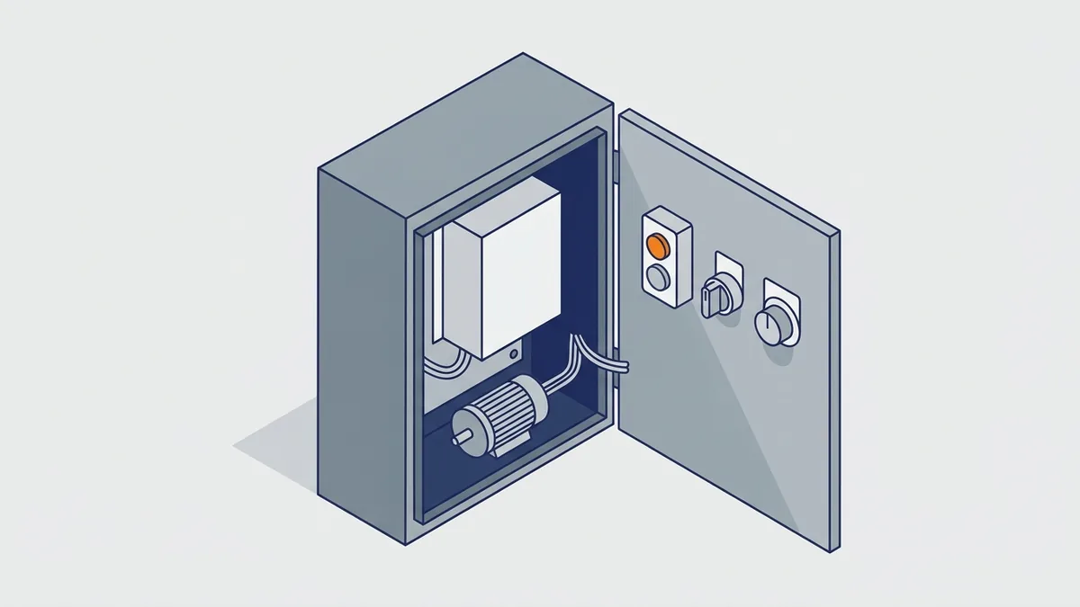
- Keypad or HMI: start, stop and speed come from the front panel or a remote operator panel.
- Terminal block: hardwired start/stop inputs plus an analog speed reference, such as 0-10 V, 4-20 mA or a potentiometer.
- PLC control: a PLC switches the terminals or sends commands over a network.
- Fieldbus or Ethernet: protocols such as Modbus and EtherNet/IP carry start, stop, speed and status data.
Remember that the command source is separate from the control mode. For example, you can run V/Hz from a network or vector from a keypad. Also, many drives let you switch between local and remote control.
Ramps, preset speeds and PID
Next, set how the drive changes speed. Acceleration and deceleration ramps set how many seconds the motor takes to reach or leave a speed. Preset speeds let digital inputs pick fixed speeds without an analog signal. Finally, the built-in PID loop compares a feedback signal, such as pressure, flow or temperature, to a setpoint and adjusts speed to hold it.
Stop modes and braking
You also choose how the drive stops. Coast-to-stop shuts off output and lets the load spin down. Ramp-to-stop follows the decel ramp instead. DC injection braking feeds DC into the motor to slow or hold it at low speed. When ramps are short or loads are heavy, a dynamic braking resistor burns off extra bus energy as heat.
How do you size a braking resistor for a decel time and load inertia?
Start with the energy the load stores. Kinetic energy in joules equals one half times inertia (kg·m²) times angular speed squared. Angular speed in rad/s equals rpm times 0.105. Then divide that energy by the decel time to get average braking power.
For example, take a load with 2 kg·m² of inertia at 1800 rpm, which is about 188.5 rad/s. The stored energy is about 35,500 J. Stopping it in 5 seconds gives about 7.1 kW of average power. With a constant-torque ramp, peak power runs about twice the average, so near 14 kW.
Next, check the limits. Friction and windage help you, so this figure is a conservative upper bound. However, the resistor’s ohm value must not fall below the drive’s stated minimum, and the resistor needs a watt rating that fits your duty cycle (how often and how long you brake). Drive makers publish resistor tables for their models, so use those. If you brake often or hold an overhauling load, a regen unit may be the better choice, because it returns the energy to the line instead of burning it.
For brand-specific setup, see our training lessons on Lenze SMV potentiometer wiring and ABB ACS355 advanced speed control. Parameter numbers differ by model and firmware, so always confirm them in the user manual.
Why Use a Variable-Speed Drive? Energy and Process Benefits
Why use variable-speed drives at all? The biggest reason is energy on centrifugal pumps and fans. According to the US Department of Energy (DOE), about 60% of the energy used by industrial motor-driven systems goes to pumps, fans and compressors. Many of those machines run at full speed while a valve or damper throttles the flow, which wastes power.
How much energy can a VFD save on pumps and fans?
The affinity laws explain the savings. For centrifugal pumps and fans, these rules apply:
- Flow is proportional to speed.
- Pressure (head) is proportional to speed squared.
- Power is proportional to speed cubed.
For example, say you slow a pump from 60 Hz to 48 Hz to cut flow by 20%. That is 80% speed, and 0.8 cubed is about 0.51. So in an ideal, friction-only system, the pump needs about 51% of its full-speed power.
DOE says savings of 50% or more may be possible when centrifugal fan and pump motors follow the load. It also says VFDs save far more than throttling or bypass flow control. In addition, its Variable Speed Pumping guide reports 30% to 50% savings in many pump installations. DOE also estimates that 75% of pump systems are oversized, many by more than 20%.
When savings shrink: static head and constant-torque loads
However, the affinity laws do not fit every system. DOE warns that a common mistake is to use them to figure savings where static head is present. Static head is the fixed lift a pump must overcome, such as raising water into a tank. In that case the pump cannot slow down much before flow drops off, so real savings fall well short of the cube law.
Likewise, constant-torque loads save much less. Conveyors, positive-displacement pumps and many compressors need about the same torque at any speed. On those loads, power falls roughly in step with speed, not with its cube. So measure or run a real calculation before you promise savings from variable-speed drives.
Other benefits
Energy is not the only payoff. Controlled starts cut inrush current and mechanical shock on belts, couplings and gearboxes. You also get precise process control without valves or dampers. Pumps that run slower tend to wear less, too. For more on this, see our post Benefits of Using a Variable Speed Drive.
Where Variable-Speed Drives Are Used
Which applications benefit from a VFD? Variable-speed drives pay off wherever a motor should not always run flat out. Here are the common jobs, with the control mode that usually fits:
- Centrifugal pumps: V/Hz or sensorless vector, often with PID on pressure or flow. Process drive families fit well.
- Fans and HVAC: V/Hz in most cases. HVAC drives, such as the Altivar HVAC ATH200, target this work.
- Compressors: savings and control needs depend on compressor type, so check the maker’s guidance.
- Conveyors: V/Hz for light loads, and sensorless vector for heavy or loaded starts.
- Mixers and extruders: sensorless vector for strong low-speed torque.
- Hoists and cranes: closed-loop vector with brake control.
- Machine tools and packaging lines: compact machine drives, often on a network with a PLC.
- Solar pumping: dedicated solar pumping drives run a pump from solar panels.
For hoists, set the drive’s brake-control output with care. It should apply the mechanical brake below a set speed. Likewise, the drive should release the brake only after motor flux is established. That keeps the load from dropping during the handoff.
How to Select and Size a Variable-Speed Drive
How do you size and select a VFD for your motor and load? Start by gathering this information before you pick a model:
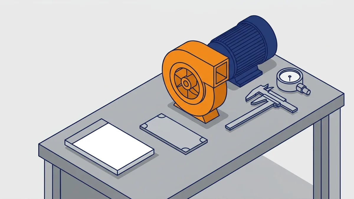
- Motor nameplate: voltage, full-load amps (FLA), hp or kW, rpm and frequency
- Supply voltage and number of phases
- Load type: variable torque (fans, centrifugal pumps) or constant torque (conveyors, hoists)
- Duty rating: normal duty or heavy duty overload
- Overload current needed at start, and for how long
- Environment and enclosure rating (IP or NEMA type)
- Altitude and ambient temperature, which can force derating
- Motor cable length
- Control I/O and network protocol needed
- Safety functions the machine requires
Size by current and duty, not only horsepower
Size the drive by motor full-load current and duty rating, not by horsepower alone. Motors of the same horsepower can draw different currents, especially at different speeds and pole counts. So make sure the drive’s continuous output current meets or beats the motor FLA.
Next, match the duty rating. Normal duty suits variable-torque loads like fans and pumps, which need little overload. Heavy duty suits constant-torque loads that need more overload current for longer, such as conveyors and hoists. For example, Schneider catalogs list separate normal duty (ND) and heavy duty (HD) currents. Rockwell catalog numbers encode the normal duty rating, so check the heavy duty figures in the technical data.
Motor and supply checks
Also, check whether the existing motor is inverter duty (VFD rated) before you reuse it. Older motors may not handle the fast voltage edges of a PWM drive, so check NEMA MG1 Part 31 and the motor maker’s data. In addition, DOE suggests reviewing motor size if a motor runs below 50% load for long periods.
Supply matters too. Small variable-speed drives often accept single-phase input. For example, the Altivar Machine ATV320 comes in single-phase 200-240 V and three-phase 200-240 V, 380-500 V and 525-600 V versions. Finally, apply the manual’s derating for altitude, ambient temperature and switching frequency.
How much do altitude, temperature and switching frequency derate a drive?
The amount depends on the drive, so use the derating curve or table in its technical data. Still, a common pattern for altitude is a loss of about 1% of rated current per 100 m above 1000 m. For example, at 2000 m a 30 A drive following that rule would give about 27 A.
Ambient temperature works the same way. Drives carry full current up to a stated temperature, often 40 °C for open or standard mounting, and then lose current as it rises. Higher switching frequency also cuts the allowed current, because the IGBTs make more heat. Apply each derating the manual lists, and then size up to the next drive frame if the result falls below motor FLA.
Allen-Bradley PowerFlex Drives (Rockwell Automation)
What is an Allen-Bradley VFD?
An Allen-Bradley VFD is an AC drive from Rockwell Automation. Allen-Bradley is Rockwell’s brand, and PowerFlex is the name of its drive family. So when someone asks for a PowerFlex, they mean an Allen-Bradley drive.
What does “VFD AB” mean?
In most searches, AB is short for Allen-Bradley. So “vfd ab” means an Allen-Bradley PowerFlex drive. You may also see it typed as “allan bradley vfd,” but the correct spelling is Allen-Bradley.
Which PowerFlex models are there?
Rockwell’s PowerFlex Low Voltage Drives Selection Guide (PFLEX-SG002) lists the families below. Lifecycle status changes over time, so check Rockwell’s product lifecycle status before you specify a model.
| PowerFlex family | Class | Notes from Rockwell literature |
|---|---|---|
| PowerFlex 4M | Compact | Small compact-class drive |
| PowerFlex 400 | Fan and pump | Built for fan and pump work |
| PowerFlex 523, 525, 527 | Compact (520-series) | 525 is for simple machine integration and has embedded EtherNet/IP; 527 is designed for use with a Logix controller |
| PowerFlex 70 | Architecture | Architecture-class drive |
| PowerFlex 753 | Architecture | Cost-effective general-purpose drive |
| PowerFlex 755 | Architecture | Architecture-class drive |
| PowerFlex 755T (755TL, 755TR, 755TS) | Architecture | Uses TotalFORCE technology |
Allen-Bradley manuals and software
Get PowerFlex documents from the Rockwell Automation Literature Library. Each product page, such as the PowerFlex 525 page, lists the publication numbers you need. For the 525, those are the User Manual (520-UM001), Technical Data (520-TD001) and Product Brochure (520-BR001). The same pages offer Connected Components Workbench (CCW) and DriveTools SP database files, plus EDS files for network setup.
Also, pull two general guides that apply to every PowerFlex job. Wiring and Grounding Guidelines for PWM AC Drives (DRIVES-IN001) covers how to install, protect, wire and ground PWM drives. Preventive Maintenance of Industrial Control and Drive System Equipment (DRIVES-TD001) covers upkeep.
Here is one practical tip. The PowerFlex 700 User Manual (20B-UM001) covers programming and troubleshooting, but not installation and wiring. Instead, wiring lives in separate installation instructions, such as 20B-IN019 for frames 0 to 6. So pull both before you start.
Schneider Electric Altivar Drives
What Schneider Electric VFDs are there? If you want a Schneider Electric VFD, look for the Altivar name. Altivar soft starters and variable-speed drives cover motor control up to 20 MW, from small machine drives to medium-voltage drives. The ranges split by job: machine drives for OEM equipment, and process drives for plant systems.
How do the Altivar machine ranges differ?
The machine and small-equipment ranges differ mainly in power and mounting. Here is a quick map based on Schneider’s range pages and catalogs:
| Altivar range | Power range | Typical use |
|---|---|---|
| Altivar 12 | 0.18 to 4 kW | Commercial equipment |
| Easy Altivar 310 | 0.37 to 22 kW (0.5 to 30 hp) | Simple machines; separate ND and HD ratings |
| Altivar Machine ATV320 | 0.18 to 22 kW (0.25 to 30 hp) | Machine drive; single- or three-phase input |
| Altivar Machine ATV340 | 0.75 to 75 kW (1 to 100 hp) | Larger machines |
| Altivar Machine ATV350 | 0.75 to 11 kW (1 to 15 hp) | On-machine mounting; IP66/NEMA 4X (indoor) or IP54/NEMA 12 |
Altivar Process, HVAC and medium-voltage ranges
Altivar Process drives handle pumps, fans, compressors, conveyors and other plant loads, with process drives up to 2600 kW. Schneider’s global category page lists Altivar Process fluid-management drives from 0.75 kW to 800 kW. For buildings, the Altivar HVAC ATH200 covers 0.37 to 22 kW. Schneider also offers a solar pumping range. At the top end, the Altivar Process ATV6000 is the medium-voltage drive.
Find Altivar documents on se.com, Schneider Electric’s website. Product pages carry catalogs, manuals and data sheets to download. For example, the Altivar Machine ATV320 catalog lists features, specifications, accessories and supply voltage options. Schneider’s US site also has a “Discontinued AC Drives” section, so check status before you order a replacement.
Installing and Commissioning a VFD
How do you install and commission a VFD? Start with the manual for the drive in hand, because mounting and wiring rules differ by model. Then follow these basics:
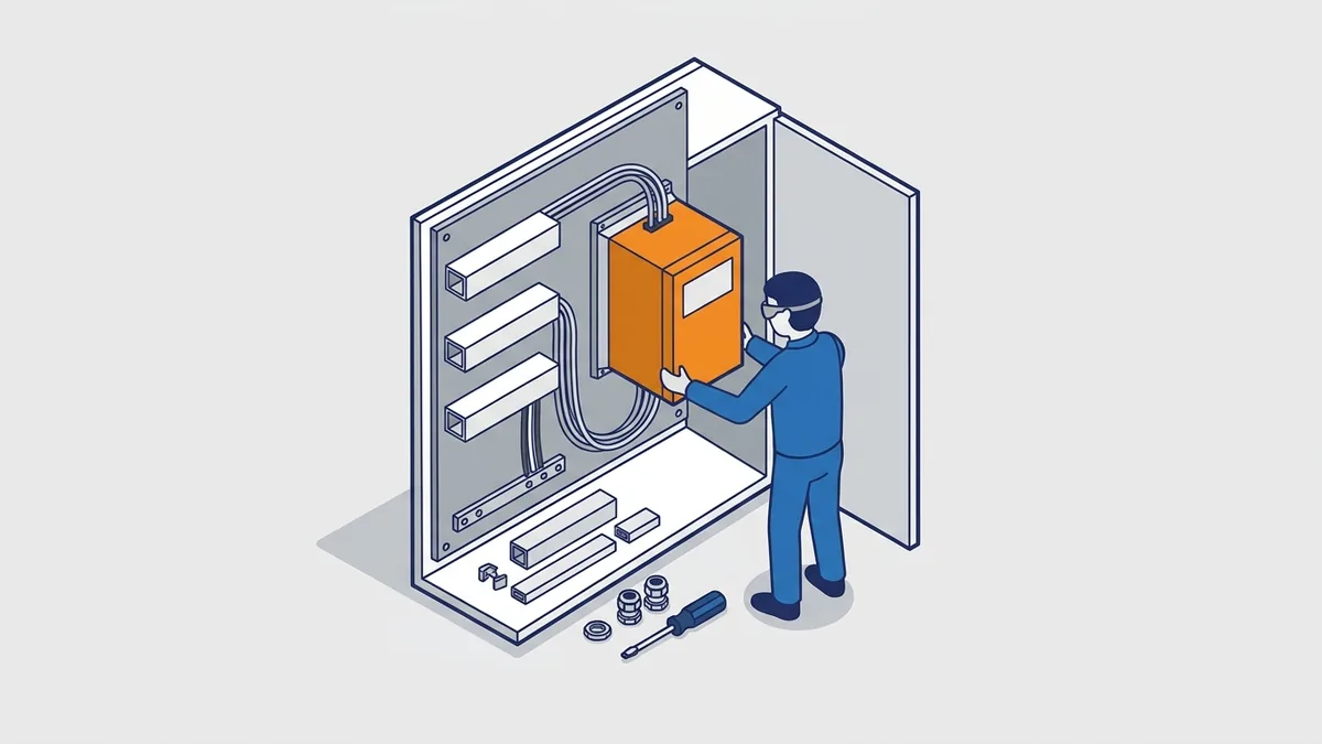
- Mount the drive with the clearances the manual gives, and keep cabinet air cool and clean.
- Follow the maker’s wiring and grounding guide, such as Rockwell’s DRIVES-IN001.
- Ground and bond the drive, motor and cabinet properly, because PWM drives need a solid ground path.
- Keep power and control wiring in separate runs, and cross them at right angles.
- Use shielded motor cable where the manual calls for it.
- Stay within the maximum motor cable length for your drive and switching frequency.
What are the maximum motor cable lengths, and when do you need a reactor or filter?
No single length fits every drive. The limit depends on the drive model, voltage, switching frequency and whether the cable is shielded. So find the maximum length in the manual or catalog, as with the 4 kHz figures in Schneider’s Easy Altivar 310 catalog.
Long leads cause trouble because the fast PWM edges bounce back from the motor end of the cable. This reflected wave can push motor terminal voltage well above the bus voltage and stress the insulation. Here is when each device helps:
- Output reactor: a series coil that softens current spikes. Use it when you are near the maker’s length limit or run several motors on one drive.
- dV/dt filter: slows the voltage rise at the motor. Use it for long leads or when the motor is not fully inverter duty.
- Sine filter: turns the output close to a true sine wave. Use it for very long leads, older motors, or step-up transformers between drive and motor.
Also, filters drop some voltage, so check the filter maker’s limits and the drive manual before you pick one.
What branch-circuit protection, disconnect and conductors does a drive need?
Start with the drive manual. It lists the fuse or breaker types, and often the maximum size, that the drive is listed to use. Those listings tie to the drive’s short-circuit rating, so do not swap in other types.
In the US, NEC Article 430 covers adjustable-speed drive systems. For the input conductors, section 430.122 sizes them at 125% of the drive’s rated input current. You also need a disconnect that follows Article 430, and local rules may add more. Outside the US, IEC rules and your local code apply, so follow those and the manual. When in doubt, ask the drive maker or a qualified engineer.
Basic start-up sequence
Once the wiring checks out, commission the drive in this order. Exact parameter names differ by brand, so follow the user manual:
- Confirm the supply voltage and phase match the drive rating.
- Enter the motor nameplate data: voltage, FLA, power, rpm and frequency.
- Choose the control mode. A good first run uses V/Hz before you move to vector.
- Run autotune if you use a vector mode.
- Set minimum and maximum frequency.
- Choose acceleration and deceleration ramps.
- Enter the motor overload protection settings.
- Jog to check rotation, run unloaded, and then run loaded.
After the loaded run, watch current, bus voltage and drive temperature for a while. Then save a backup copy of the parameters.
How do you set overload, minimum speed and cooling for a self-cooled motor at low speed?
Set the electronic overload to the motor nameplate FLA, not the drive rating. Many drives also offer a low-speed overload setting, since a motor shaft fan moves less air as speed drops. Use it when the manual offers it.
Next, set minimum speed from the motor maker’s speed-torque curve. A self-cooled motor (one with a fan on its own shaft) can overheat at low speed under full torque. You then have three choices: limit minimum speed, reduce the load torque, or add cooling. A separate constant-speed blower is the usual fix. A motor thermistor wired to the drive gives extra protection.
If one drive runs several motors, give each motor its own overload device, because the drive’s overload sees only the total current.
Safety before you open a drive
Variable-speed drives store dangerous energy in the DC bus capacitors after power is removed. So follow lockout/tagout first. Next, wait the discharge time stated in the manual for that drive. Finally, verify zero voltage on the DC bus with a properly rated meter before you touch anything.
How long is the DC bus discharge wait, and what meter or PPE do you need?
The wait is printed on the drive’s warning label and in the manual. For many drives it runs a few minutes, and larger drives can need longer, so never rely on a rule of thumb. Also, the drive’s charge light is not proof that the bus is dead.
To verify zero volts, measure at the DC bus terminals the manual names. Use a meter rated for the job, meaning a CAT III or CAT IV meter with a voltage rating above the bus voltage. For a 480 V drive, bus voltage is near 650 V DC. Test the meter on a known live source before and after. Your arc-flash risk assessment sets the PPE, such as voltage-rated gloves and eye and face protection, under NFPA 70E or your site rules.
Common VFD Problems and Mistakes
What are the most common VFD mistakes? Many trips trace back to setup, not to a failed drive. Watch for these:
- Wrong or missing motor nameplate data
- No autotune on a vector-mode drive
- Drive sized for normal duty on a heavy-duty, high-overload load
- Motor not rated for inverter duty
- Long motor leads with no output filter or reactor
- Poor grounding and bonding
- A self-cooled motor run slowly at full torque with no extra cooling
- Affinity-law savings promised on a static-head system
Typical VFD fault codes and first checks
Fault names and numbers differ by brand, so look up the exact code in the manual. Still, most variable-speed drives report the same basic fault types:
| Fault | Common causes | First checks |
|---|---|---|
| Overcurrent | Accel ramp too short, jammed load, motor or cable fault | Lengthen accel, check the load, test motor and cable insulation |
| Overvoltage | Decel too fast, overhauling or regenerating load | Lengthen decel, add a braking resistor or regen unit, check supply |
| Undervoltage or phase loss | Supply dip, blown fuse, loose terminal | Measure all input phases, check fuses and connections |
| Overtemperature | Failed fan, dust, hot cabinet, high switching frequency | Clean the heatsink, check fans, review derating |
| Ground fault | Damaged motor cable or winding insulation | Disconnect the drive, then test motor and cable insulation |
| Motor overload | Wrong FLA setting, real overload, low-speed cooling | Check nameplate settings and measure motor current |
What do specific PowerFlex and Altivar fault codes mean?
Here are common codes on two popular families. On the PowerFlex 520-series drives (523, 525, 527), codes start with F. Other PowerFlex families number faults differently, so use the manual for your model. Altivar drives show letter codes on the display.
| Fault type | PowerFlex 520-series | Altivar (ATV320 and similar) |
|---|---|---|
| Undervoltage | F004 UnderVoltage | USF |
| Overvoltage | F005 OverVoltage | ObF (overbraking) or OSF (mains overvoltage) |
| Motor overload | F007 Motor Overload | OLF |
| Overtemperature | F008 Heatsink OvrTemp | OHF |
| Overcurrent | F012 HW OverCurrent | OCF |
| Ground fault | F013 Ground Fault | Short-circuit or ground fault codes (SCF family) |
| Input phase loss | Check the manual | PHF |
Even so, confirm each code in your drive’s fault table, because names shift between models and firmware. The manual also lists the exact reset steps and causes.
Harmonics and motor effects
PWM drives create harmonics, which are distorted currents on the supply line. They also send fast voltage edges down the motor cable, and long leads can make that stress on motor insulation worse. Line reactors, harmonic filters, output filters and VFD-rated motors all help. For exact limits, check IEEE 519 for harmonics, NEMA MG1 Part 31 for inverter-duty motors, and your drive manual.
What are the IEEE 519 limits, and how do you choose a harmonic fix?
IEEE 519 sets limits at the point of common coupling (PCC), where your plant meets the utility. It does not set limits at the drive terminals. The current limit, called total demand distortion (TDD), depends on the ratio of available short-circuit current to your maximum load current. For systems from 120 V to 69 kV, the general limits are:
| Short-circuit ratio (Isc/IL) | TDD limit |
|---|---|
| Under 20 | 5% |
| 20 to under 50 | 8% |
| 50 to under 100 | 12% |
| 100 to under 1000 | 15% |
| 1000 and above | 20% |
The standard also limits voltage distortion by bus voltage, and its edition matters, so read the current IEEE 519 for those figures. Then pick the fix that fits the gap:
- Line reactor: a low-cost coil, commonly about 3% to 5% impedance, that trims harmonics and protects the drive from supply spikes.
- DC choke: does a similar job inside the drive. Many drives include one.
- Active front end: an IGBT rectifier that gives the lowest harmonics and can return braking energy. It costs more.
Start with the cheapest option, and step up only if a calculation or measurement at the PCC shows you still exceed the limit.
Maintenance, Repair or Replace a VFD
What maintenance does a VFD need?
Variable-speed drives need little upkeep, but heat and dirt shorten their life. So build these tasks into your PM schedule:
- Keep heatsinks and cooling fans clean.
- Check power connections for tightness, following the manual.
- Inspect DC bus capacitors on older drives for bulging or leaks.
- Keep the cabinet cool and its filters clean.
- Back up parameters with vendor software: CCW or DriveTools SP for PowerFlex, and SoMove for Altivar.
For a full checklist, Rockwell’s DRIVES-TD001 covers preventive maintenance of drive equipment.
When should a VFD be repaired?
Repair makes sense when the drive is still supported and the fault is in a repairable part. Common repair triggers include a failed IGBT or power module, worn bus capacitors, dead fans, a failed control board and blown input fuses. Also, repeated overvoltage or overcurrent trips with no outside cause often point to an internal fault. Precision Electric repairs drives, so back up the parameters before you send a unit out.
When should a VFD be replaced?
Replace the drive when the model is obsolete and parts are no longer available. You may also replace it to gain features, such as a built-in network port or newer safety functions. For buying options, see our post Buy Variable Speed Frequency Drives Online.
Where to Find VFD Manuals, Software and Replacement Drives
Where do you find VFD manuals, parameter files and software? Go to the manufacturer first. For Allen-Bradley, use the Rockwell Automation Literature Library and the PowerFlex product pages.
Altivar documents live on se.com. Other brands post theirs on the maker’s own website. Pull these document types for any drive:
- User manual for parameters and fault codes
- Installation instructions for mounting and wiring
- Technical data or catalog for ratings and derating
- Wiring and grounding guide
- Software files, such as CCW, DriveTools SP and EDS files for PowerFlex
For the energy case, read DOE’s Improving Motor and Drive System Performance sourcebook. Also read DOE’s Variable Speed Pumping guide. For other brands, see our posts on ABB drives, Lenze drives, the Hitachi WJ200 and DC drives.
What to have ready when you ask for a quote
Before you call for a replacement or repair quote, gather these details:
- Full catalog number from the drive label
- Drive nameplate data
- Series and firmware revision
- Motor nameplate data
- A short description of the application and load
What Does a Variable-Speed Drive Cost?
What does a variable-speed drive cost? The price depends on several factors, and we found no official price source to quote. So use these factors to compare options:
- Power and current rating
- Supply voltage and phase
- Enclosure rating
- Brand and drive family
- Options, such as network cards, encoder cards and filters
- Condition: new, surplus or repaired
How long is payback on a VFD?
Payback depends on your load and energy rate, so no single number applies. Still, the biggest savings come on centrifugal pumps and fans that run at reduced load much of the time. To estimate it, use simple payback: installed cost divided by annual energy savings. Annual savings equal the kWh saved per year times your electricity rate.
On constant-torque or static-head systems, savings shrink, so measure before you decide. In addition, many utilities calculate VFD savings using methods described in DOE’s Uniform Methods Project. Ask your utility whether it offers a rebate program.
Frequently asked questions
What are variable speed drives?
A variable speed drive is an electronic controller that sets the speed and torque of an AC motor. It works by changing the frequency and voltage supplied to the motor. Most people call these VFDs, AC drives or adjustable speed drives.
How do VFDs work?
A VFD converts incoming AC to DC with a rectifier, then smooths and stores it on a capacitor DC bus. Next, IGBTs in the inverter use pulse width modulation to build AC at the frequency and voltage needed. Because motor speed follows frequency, changing the output frequency changes speed.
How do variable frequency drives work with the motor?
The drive raises or lowers output frequency and scales voltage with it, which keeps the V/Hz ratio steady. This holds motor flux and torque steady across the speed range. Vector modes add a motor model, and sometimes an encoder, for better low-speed torque.
What is the difference between a VSD and a VFD?
In everyday use, they mean the same thing for AC motors. “Variable speed drive” is the broader term, because it also covers DC drives. A VFD varies the frequency of the AC supply to control speed.
Does “VFD AB” mean an Allen-Bradley drive?
Yes, in most searches. Allen-Bradley is Rockwell Automation’s brand, and its VFDs are the PowerFlex family, including the 4M, 525, 527, 753 and 755. Schneider Electric’s equivalent brand is Altivar.
Will a VFD save energy on any motor?
No. Savings are largest on centrifugal pumps and fans that run below full flow, because power falls roughly with the cube of speed. However, constant-torque loads and systems dominated by static head save much less.
Variable-speed drives pay off when the drive, control mode and settings match the load. Start with the motor nameplate and load type, size by current and duty, and keep the manual close during setup and troubleshooting. If you need help choosing a drive, a quote on a replacement or a repair on a failed unit, contact Precision Electric and our team will be glad to help.