








Motor and VFD: How They Work Together and How to Set Them Up
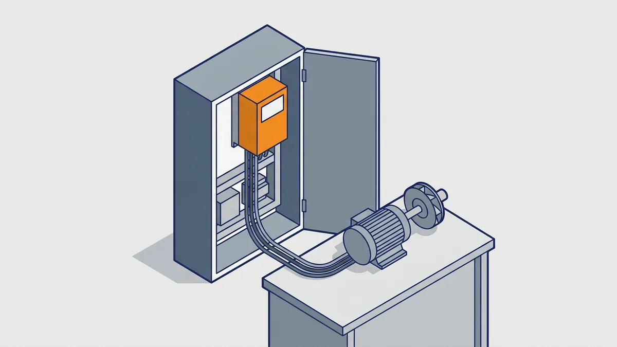
Pairing a motor and VFD looks simple, but the two work as one system, and one mistake can cost you both. This guide shows how a drive controls a motor, which motors suit one, and how to size, install, wire and set up the pair. You will also learn about DC drives, common faults and when to send equipment for repair.
On this page
- What Does a VFD Do for a Motor?
- How Does a VFD Work on a Motor?
- Why Frequency Sets Speed in a Motor and VFD
- What Are the Rectifier, DC Bus and Inverter in a VFD?
- Volts per Hertz and Starting Boost on a Motor and VFD
- What Happens When a VFD Driven Motor Slows Down?
- How Do You Size a Braking Resistor or Regenerative Unit?
- Scalar V/Hz Versus Vector Control for an AC Drive and Motor
- Which Motors Work With a VFD?
- What Is an Induction Motor VFD Setup?
- Single-Phase Motors With a VFD Are a Special Case
- How PWM Power Stresses a VFD Driven Motor
- Inverter-Duty Motors and Why Insulation Matters
- Do You Need an Inverter-Duty Motor on a VFD?
- How Long Can the Leads Be Between a Motor and VFD?
- What Lead Lengths Are Typical, and What Is the Critical-Length Rule?
- Speed Range and Cooling: Running a Motor With VFD Control at Low Speed
- What Are Bearing Currents on a VFD Driven Motor?
- Which Bearing-Current Countermeasures Should You Use, and When?
- DC Motor Variable Speed Drives
- How to Size a VFD for a Motor
- Should You Size a VFD by HP or by Amps?
- Step 1: Read the Motor Nameplate
- Step 2: Match the Motor and VFD Duty Rating to the Load
- Step 3: Derate for Heat, Altitude and Carrier Frequency
- Step 4: Match Input Voltage and Phase
- What Are Typical Derating Numbers?
- Step 5: Check Special Cases
- Step 6: Size Upstream Conductors and Protection
- How Do You Set Motor Overload and Short-Circuit Protection Under NEC?
- What Size VFD Do You Need for a 10 HP Motor?
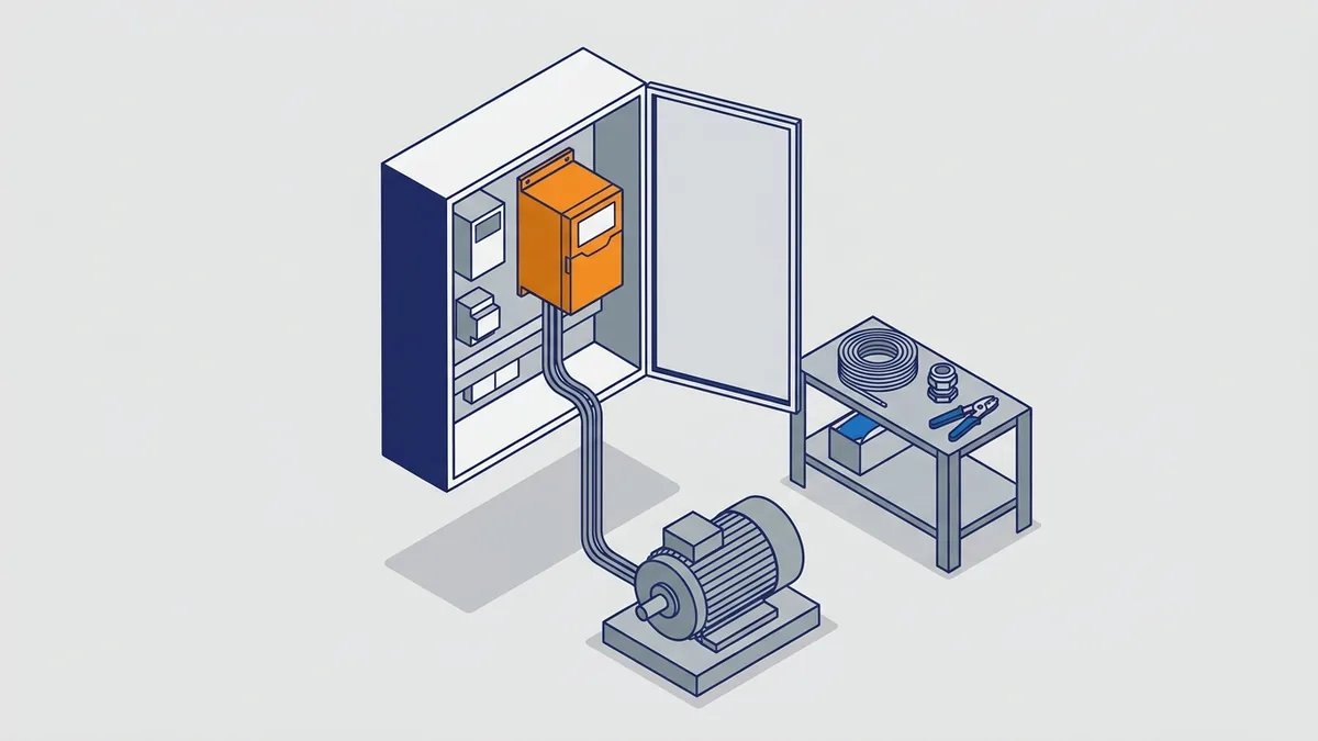
- How to Install a VFD on a Motor
- How to Wire a VFD to a Motor
- Start-Up and Parameter Setup for a Motor and VFD
- Common Mistakes and Troubleshooting a Motor and VFD
- When to Repair, Replace or Call for Help With a Motor and VFD
- Frequently asked questions
What Does a VFD Do for a Motor?
A variable frequency drive (VFD) is an electronic controller between your power supply and an AC motor. It sets the frequency and voltage the motor receives. As a result, motor speed is no longer locked to the line frequency. In a motor and VFD system, you choose the speed, and the drive delivers it.
What You Gain From a Motor With VFD Control
So what does a VFD do for a motor? In short, it controls how the motor starts, runs and stops. Here is what the drive gives you:
- Speed control: you can run the motor at any speed in its allowed range, not just full speed.
- Controlled acceleration and deceleration: ramps set how fast the motor speeds up and slows down.
- Lower starting stress: the drive starts at low frequency. This avoids the inrush and torque jolt of across-the-line starting, which connects the motor straight to full line voltage.
- Energy benefit on fans and pumps: variable-torque loads can often use less energy at reduced speed than with dampers or throttling valves.
For more detail, see our post on AC motor VFD benefits and key features. Also, our energy-savings post covers fans and pumps in depth.
What Is the Difference Between a VFD and a Soft Starter?
A soft starter ramps voltage up at start and down at stop. However, once the motor reaches full speed, it runs at line speed. Tractian’s VFD glossary notes that soft starters cost less than VFDs.
Still, they offer no speed control and no energy savings while the motor runs. So pick a soft starter when you only need a gentle start. Instead, choose a VFD for electric motor jobs that need speed control while running.
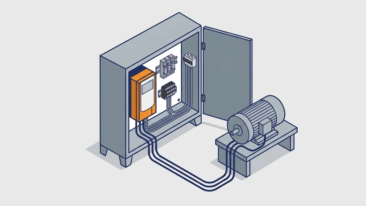
How Does a VFD Work on a Motor?
A drive changes motor speed by changing frequency. To do that, it rebuilds the AC waveform from scratch. Here is how the motor and VFD work together, step by step.
Why Frequency Sets Speed in a Motor and VFD
How does a VFD work in a motor, and why does frequency change speed? An AC motor’s speed follows its supply frequency. Synchronous speed, the speed of the rotating magnetic field, is: rpm = 120 × frequency ÷ number of poles. For example, a 4-pole motor at 60 Hz has a synchronous speed of 1,800 rpm. At 50 Hz, the same motor’s field turns at 1,500 rpm.
However, an induction motor runs slightly below synchronous speed. This small gap, called slip, lets the rotor produce torque. So a 4-pole, 60 Hz motor shows a little less than 1,800 rpm on its nameplate. Because speed follows frequency, a drive that lowers frequency lowers speed.
What Are the Rectifier, DC Bus and Inverter in a VFD?
Every drive works in three stages, as KEB America’s article on pulse-width modulation explains:
- Rectifier (converter): a diode bridge converts incoming AC to pulsating DC.
- DC bus: a capacitor bank smooths the DC and stores some energy.
- Inverter: IGBTs, which are fast electronic switches, chop the DC bus voltage into pulses.
The inverter uses pulse-width modulation (PWM), which varies the width of each pulse. Then the motor windings turn those pulses into current that acts like AC at the commanded frequency. For example, a drive on a 480 VAC supply has a DC bus of about 678 VDC. Remember that number, because it matters for motor insulation.
Volts per Hertz and Starting Boost on a Motor and VFD
A drive raises and lowers voltage along with frequency. This constant volts-per-hertz (V/Hz) ratio keeps the motor’s magnetic flux, and so its torque, steady across the speed range. To run a motor at half speed, the drive halves both voltage and frequency. For example, a 460 V, 60 Hz motor at 30 Hz gets about 230 V.
Drives usually start a motor at very low frequency and ramp up. Also, if the load needs more starting torque, you can add voltage boost, set as a percentage of rated voltage. According to Joliet Technologies’ summary of NEMA MG 1 guidelines, rated torque at start-up needs at least rated current.
What Happens When a VFD Driven Motor Slows Down?
When you command a lower speed, the load’s inertia can keep the shaft turning faster than the new synchronous speed. At that point, the motor acts as a generator. As a result, it sends energy back into the DC bus and raises the bus voltage. That is why drives offer braking resistors, which burn off the extra energy as heat. You can also lengthen the deceleration ramp so the load slows more gently.
How Do You Size a Braking Resistor or Regenerative Unit?
Start by finding how much energy the load returns when it stops. Then match a resistor to that energy and to the drive’s limits. Follow these steps:
- Find the braking energy. Kinetic energy is ½ × J × ω², where J is the load inertia and ω is speed in rad/s (rpm × 0.1047). Peak braking power is braking torque × speed.
- Find the duty cycle. Divide the energy per stop by the time of the full cycle. The result is the average power the resistor must handle.
- Pick the resistance. Peak braking power equals bus voltage squared divided by resistance. Choose an ohm value at or above the drive’s stated minimum.
- Check the watt ratings. The resistor needs a continuous rating for the average power and a pulse rating for each stop. Also look for built-in thermal protection.
Your drive also needs a brake chopper, which switches the resistor on. Many drives build one in, and others offer it as an option. Use the drive maker’s selection tables when they list resistors for your model.
Consider a regenerative unit instead when stops are frequent or long. The same goes for overhauling loads, such as downhill conveyors, cranes and unwinders. A regenerative unit sends the energy back to your power line instead of burning it as heat. As a result, it also cuts the heat in the panel or room.
Scalar V/Hz Versus Vector Control for an AC Drive and Motor
Most drives offer two main control modes. Scalar V/Hz control holds the volts-per-hertz ratio, and it works well for fans and pumps. In contrast, vector control uses a model of the motor to control flux and torque separately. So choose vector control when you need high starting torque or precise speed.
Which Motors Work With a VFD?
Not every motor suits a drive in the same way. The type of motor, its insulation and its cooling all matter. Start with the most common case.
What Is an Induction Motor VFD Setup?
The most common motor and VFD pairing is a three-phase AC induction motor on a three-phase drive. An induction motor VFD setup means the drive feeds the motor’s three leads in place of a starter. Induction motors are rugged and common, and drive makers design most drives around them. So if you have a three-phase induction motor in hand, a VFD is usually a good fit.
Single-Phase Motors With a VFD Are a Special Case
Single-phase motors are different. Many use start capacitors or centrifugal start switches, which do not suit a variable-frequency output. Therefore, check with the motor and drive makers before you try it. Our SMV single-phase motor post covers this case in more detail.
How PWM Power Stresses a VFD Driven Motor
PWM output is not a clean sine wave. Because of that, a VFD driven motor faces stresses that a line-fed motor does not:
- Fast voltage rise times (high dV/dt, meaning the voltage changes very quickly).
- Voltage spikes at the motor terminals, especially on long leads.
- Extra heating from harmonics in the current.
- Less cooling at low speed on fan-cooled motors.
- Bearing currents that can pit the bearings.
Inverter-Duty Motors and Why Insulation Matters
Reflected wave is the main threat to motor insulation. The motor cable acts like a transmission line, and the motor’s surge impedance does not match the cable’s. As a result, each fast pulse reflects at the motor and builds on itself. Rockwell’s AC drive application technique, in the Rockwell Automation Literature Library, says up to twice the DC bus voltage can appear at the motor terminals. On a 480 V drive with a 678 VDC bus, that means peaks near 1,350 V.
NEMA MG 1 Part 31 sets the benchmark for definite-purpose inverter-fed motors. For low-voltage motors rated 600 V and below, the current edition sets the limit at 3.1 × rated line-to-line voltage. That is about 1,426 V peak for a 460 V motor, with rise times of 0.1 µs or longer. Older editions and older Rockwell literature give 1,600 V. Part 30 covers general-purpose motors on drives and sets a lower limit. So a Part 31 motor gives you more margin.
Do You Need an Inverter-Duty Motor on a VFD?
Not always, but the motor insulation must survive the spikes your drive and cable produce. Watch the label, though. Eaton Application Note AP040013EN, The Reflective Wave Phenomena, warns that “inverter duty” motors are not always built for higher dV/dt or peak voltages. The term first meant insulation upgraded for harmonic heating and less cooling at low speed. So ask the motor maker whether the motor meets NEMA MG 1 Part 31.
If your motor falls short, you have four main options:
- Use a NEMA MG 1 Part 31 motor.
- Add an output reactor. Rockwell notes it slows the rise time, but peaks can still be high.
- Add a dV/dt filter at the drive output.
- Shorten the motor leads.
For more, see our inverter-rated motors FAQ.
How Long Can the Leads Be Between a Motor and VFD?
No single lead-length number fits every drive. The limit depends on the drive model, its carrier frequency (how fast the inverter switches), the voltage and the motor insulation. For example, the Delta VFD-M manual gives two limits. Motor cable should be under 20 m for 3.7 kW models and below, and under 50 m for 5.5 kW models and above. For longer cables, it says to use an AC output reactor.
So use your drive maker’s lead-length table. Beyond that length, add a reactor or filter, or use a Part 31 motor. Where sources disagree, the drive manual wins.
What Lead Lengths Are Typical, and What Is the Critical-Length Rule?
Reflection gets worse as the cable gets longer. Past a “critical length,” the peak at the motor can climb toward twice the DC bus voltage. That length gets shorter as the drive’s rise time gets faster. As a result, a fast IGBT drive can need protection on cables that seem short.
For typical figures, expect limits in the tens of meters for standard motors, as the Delta example shows. Reactors and dV/dt filters stretch that limit, and sine filters allow the longest runs. Also, 230 V drives stress insulation less than 460 V or 575 V drives. Even so, read the table for your exact drive, voltage and carrier frequency.
Speed Range and Cooling: Running a Motor With VFD Control at Low Speed
Can you run a motor slowly on a VFD without overheating it? Yes, within limits. A totally enclosed fan-cooled (TEFC) motor has a fan on its own shaft. At low speed, that fan moves much less air, while a constant-torque load still draws high current. As a result, the motor can overheat.
Before you run slowly under load, check the motor maker’s speed range and torque derating. If you need long runs at low speed and high torque, ask the motor maker about a motor rated for that range.
What Are Bearing Currents on a VFD Driven Motor?
Bearing currents are a common motor and VFD failure. High dV/dt from the drive can induce current through the motor bearings. That current causes pitting and early bearing failure.
Good grounding and shielding give the current a better path back to the drive. So use shielded VFD cable bonded at both ends and a dedicated ground wire from motor to drive. The wiring section below explains how.
Which Bearing-Current Countermeasures Should You Use, and When?
Start with the basics on every install: proper grounding, bonded shielded cable and a lower carrier frequency if the drive allows it. Then add hardware when the risk is higher, such as on larger motors or in critical service. Here are the main options:
- Shaft grounding ring: it gives common-mode current a path around the bearing. Use it on the drive end of the motor.
- Insulated bearing: a coated or ceramic bearing blocks circulating current. Many makers put it on the non-drive end, and some add a grounding ring too.
- Common-mode choke: a core placed around the three output leads cuts the common-mode current at its source.
- Sine filter or lower carrier frequency: either one softens the pulses that drive the current.
Larger motors tend to need more protection, so ask the motor maker for its rule. Several motors on one drive each need their own bearing protection. Also, a motor on a bypass starter sees PWM only while the drive runs it, so protect it for drive duty. Finally, a drive far larger than the motor may push more common-mode current, so ask both makers before you install.
DC Motor Variable Speed Drives
Can you use a VFD for a DC motor? No. A VFD makes variable-frequency AC for AC motors. Instead, a DC motor needs a DC drive, which supplies variable DC voltage to the armature. Keep the two terms separate when you order parts or ask for help.
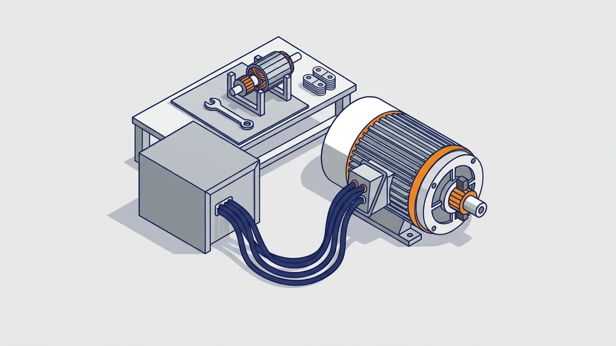
How Does a DC Motor Variable Speed Drive Work?
A DC motor variable speed drive converts AC to variable DC with an SCR bridge. SCRs, also called thyristors, are switches that turn on at a set point in each AC cycle. The drive changes that firing angle to raise or lower the average armature voltage.
On a general-purpose DC motor, shaft speed follows armature voltage almost directly. Also, armature current follows output torque at almost any speed. Below base speed, the drive holds the field flux constant.
Field Weakening and Speed Feedback
To run above base speed, the drive weakens the field. However, the field-weakening range is usually limited to about 3:1. That limit keeps the motor stable and gives good commutation, which is clean current transfer at the brushes.
For accurate speed, a closed-loop DC drive uses feedback from a tachometer or encoder. An error amplifier compares the speed reference with actual speed. Then a firing pulse generator adjusts the SCR bridge to correct the error. Many DC drives also offer a current (torque) control mode. Our DC Variable Speed Drives page at Precision Electric explains these loops further.
Permanent-Magnet Versus Wound-Field DC Motors
A shunt-wound DC motor has separate field and armature windings, so the drive must supply the field. In contrast, a permanent-magnet (PM) DC motor uses magnets for its field. As a result, it needs no field supply from the drive. Check which type you have before you choose or replace a drive.
Keep the DC System or Switch to an AC Drive and Motor?
Many plants still run reliable DC systems. If your DC motor and drive work well and parts exist, repair often makes sense. On the other hand, an obsolete drive or a worn-out motor may point you to an AC drive and motor retrofit. Precision Electric repairs DC drives and motors and can help you plan a retrofit. Share your nameplates and application details, and we can talk through both paths.
How to Size a VFD for a Motor
How do you size a VFD for a motor? Size it on current, then check duty, derating and supply. Many motor and VFD projects go wrong at this step. So follow the steps below and check each one against your drive manual.
Should You Size a VFD by HP or by Amps?
Size by amps. The drive’s continuous output current must be at least the motor’s full-load amps (FLA) after derating. FLA is the current the nameplate lists at rated load. However, two motors of the same horsepower can draw very different current. So a drive picked by horsepower alone can trip or overheat.
Step 1: Read the Motor Nameplate
Write down horsepower or kW, voltage, phase, FLA, service factor, RPM and insulation class. The nameplate FLA is your starting point, and it wins over any table. If the nameplate is unreadable, use the NEC Table 430.250 value as a stand-in. Check that table in the current NEC edition and your local code. Then verify actual current with a clamp meter under load.
Step 2: Match the Motor and VFD Duty Rating to the Load
Next, match the drive’s duty class to the load’s torque profile. Many drives list a separate rating for each class.
| Duty class | Typical loads | Typical overload to verify |
|---|---|---|
| Variable torque | Fans, centrifugal pumps | About 110–120% for 60 seconds |
| Constant torque | Conveyors, mixers, positive-displacement pumps | About 150% for 60 seconds |
Because a constant-torque load needs full torque even at low speed, it needs the higher overload rating. Check the exact figures in your drive’s data sheet.
Step 3: Derate for Heat, Altitude and Carrier Frequency
Drives lose capacity in hot rooms, at high altitude and at higher carrier frequencies. So use the derating curves in your drive manual for each condition. Then confirm the derated output current still meets or beats the motor FLA. Sources give different safety margins, so let the manual decide.
Step 4: Match Input Voltage and Phase
Pick a drive rated for your supply voltage and phase. If you feed a three-phase drive from single-phase power, you must derate it. Sources differ on the amount. So use the manufacturer’s figure, or choose a drive rated for single-phase input.
What Are Typical Derating Numbers?
Exact numbers differ by maker and model, so treat these as starting points only. Then replace them with the figures in your drive’s data sheet.
| Condition | Common starting point |
|---|---|
| Ambient temperature | Full rating up to a stated limit, often 40 °C. Above it, current drops by a set percentage per degree. |
| Altitude | Full rating up to about 1,000 m (3,300 ft). Above that, many makers derate about 1% per 100 m. |
| Carrier frequency | Full rating at the default setting. A higher carrier adds heat, so the curve cuts output current. |
| Single-phase input to a three-phase drive | Many makers call for roughly half the three-phase current rating. Some give other figures. |
Also, apply each factor in turn when two conditions occur together, such as a hot room at altitude. If the result falls below the motor FLA, move up a drive size.
Step 5: Check Special Cases
- Several motors on one drive: add up all the motor FLAs. Also add up the cable lengths to each motor when you check lead length.
- A drive much larger than the motor: a 2:1 maximum ratio of drive current to motor FLA is often quoted. Confirm it in your drive manual.
Step 6: Size Upstream Conductors and Protection
Size input conductors and protection from the drive manual and NEC Article 430. For example, training sources report that NEC 430.122(A) requires supply conductors rated at 125% of the drive’s rated input current. In addition, NEC 430.130 points you to the fuse or breaker type and size in the drive manual. Verify both in the current NEC edition and your local code.
Finally, set the drive’s electronic motor overload to the nameplate FLA. Our “Choosing the Right One” post and our SMV overload post go deeper. The Galco Motor & VFD Sizing Calculator is a handy cross-check.
How Do You Set Motor Overload and Short-Circuit Protection Under NEC?
For overload, NEC 430.124 lets a drive’s built-in electronic overload protect the motor. The drive must be listed for that job, and you must set it to the motor’s nameplate FLA. The code also expects the drive to keep its thermal memory when power is lost, or you add separate protection. Check the exact wording in your NEC edition.
For conductors between the drive and motor, size them from the motor FLA under the usual motor rules, such as 125% of FLA under NEC 430.22. Supply conductors follow the drive’s input current, as shown above.
For short-circuit protection, look at the drive’s short-circuit current rating (SCCR) on its nameplate or in its manual. The fault current available at your install point must not exceed it. Also, the manual lists the fuse or breaker types that earn that rating. Finally, buy drives listed to the standard your site needs. UL 61800-5-1 is the current UL standard for drives, and older units may cite UL 508C.
What Size VFD Do You Need for a 10 HP Motor?
Here is a worked example. A 10 HP, 460 V three-phase motor typically draws about 14 A at full load. Say it runs a centrifugal fan, a variable-torque load. With a 10% margin, 14 A × 1.10 = 15.4 A minimum. So a drive rated for 17 A or 20 A of continuous output would fit.
Your margin may differ, so follow your drive manual’s duty and derating tables. Also, use your own nameplate FLA, not this typical value.
How to Install a VFD on a Motor
How do you install a VFD on a motor? Plan the location, mount the drive, add upstream protection and run the right cable. A clean install protects both the motor and VFD for years. Eaton Drives Installation 101 and the Schneider Electric Electrical Installation Guide are good primary sources for these steps.
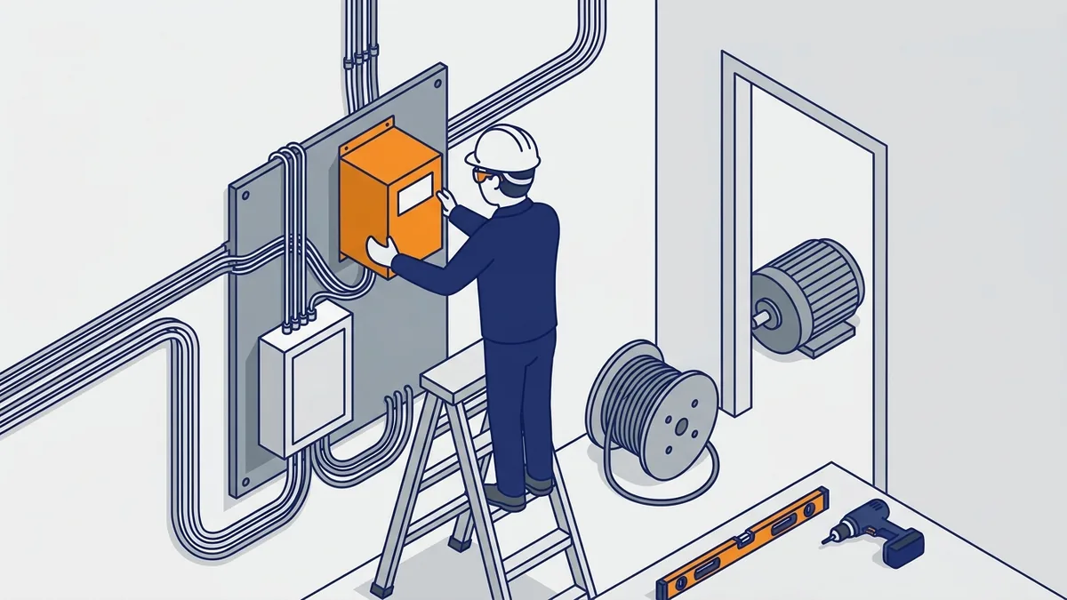
Before You Start a Motor and VFD Install
- Lock out and tag out every power source, and verify zero energy.
- Read the drive’s installation manual before you touch a wire.
- Check that the enclosure rating suits the location.
- Confirm the room’s temperature and altitude stay within the drive’s limits.
The Delta VFD-M manual stresses that only qualified people familiar with AC motor drives should install, wire and commission them. Also, your grounding method must meet the codes where you install the drive.
What Safety Steps Apply Before Servicing a Drive?
The DC bus capacitors can hold a dangerous charge after you remove power. So follow these steps before you open the drive:
- Open and lock out the disconnect, and tag it.
- Wait the time printed on the drive’s label or in its manual. Many manuals call for at least 5 minutes, and larger drives can need longer.
- Open the cover and wear the PPE your site requires for electrical work.
- Use a meter rated for the voltage to measure the DC bus terminals, often marked DC+ and DC−. Follow the manual for their location.
- Confirm the reading is at or near zero volts. Also check between the line and motor terminals.
Do not rely on a bus charge light alone, because it can fail. If the voltage does not fall, stop and call a qualified person.
Mounting the Drive
Mount the drive vertically, within ±10° per the Schneider guide, so it cools properly. Use all four mounting holes. Then leave the clearances the manufacturer lists around the drive for airflow. Also, keep the drive away from heat, dust and moisture beyond its enclosure rating.
What Upstream Protection Does a VFD Need?
Every drive needs a disconnect and short-circuit protection ahead of it. Use the fuse or breaker type and size the drive manual specifies. NEC 430.130 refers to that manufacturer data, so treat the manual as required reading. Check the current NEC edition and local code for your site.
What Input-Side Harmonic and Power-Quality Measures Apply?
A drive’s rectifier draws current in short pulses, which adds harmonics to your power system. Several parts help reduce them:
- Line reactor: it sits ahead of the drive. Common sizes are 3% and 5% impedance. It cuts harmonics and shields the drive from line spikes.
- DC link choke: it sits inside the DC bus, and many drives include one. It gives some of the same benefit as a line reactor.
- Isolation transformer: it adds impedance and separates the drive from the supply. Use it when you need a voltage change or to deal with grounding problems.
- Multi-pulse or active front-end drives: these cut harmonics much further when limits are strict.
IEEE 519 sets harmonic limits for the whole facility at the point of common coupling, where you meet the utility. It does not set limits for one drive. So first measure or estimate the total load, then pick the fix that meets the limits.
Cable Choice and Routing Between Motor and VFD
Use cable with insulation rated at least 75 °C. On the motor side, use shielded VFD cable. Schneider notes shielded cable helps meet emission limits under IEC 61800-3 Category C2 or C3. Run the motor cable continuously from drive to motor with no splices.
Next, keep input power, output power and control wiring in separate runs. Finally, check the manufacturer’s lead-length table for your voltage and carrier frequency. Beyond that length, add an output reactor or dV/dt filter, or use a Part 31 motor.
Do Not Megger Through the Drive
An insulation tester, often called a megger, applies high DC test voltage. That voltage can destroy the drive’s electronics. So disconnect the motor leads from the drive before you test the motor or cable.
How to Wire a VFD to a Motor
How do you wire a VFD to a motor? Wiring a motor and VFD correctly comes down to a few rules. Always follow your drive’s installation manual for terminal names, wire sizes and torque values.
Power Terminals on the Motor and Inverter Drive
Connect the incoming three-phase supply to the line terminals, marked L1/L2/L3 or R/S/T. Then connect the motor leads to the output terminals, marked U/V/W. Never mix these up, because line power on the output terminals can destroy the drive.
To reverse rotation, swap any two motor leads. Or use the drive’s direction parameter or input, as the manual shows. Our SMV forward/reverse post walks through that method.
Match the Motor Connection to the Drive Voltage
Many motors are dual-voltage, with wye or delta connections or two winding groups. Before you power up, confirm the motor connection matches the drive’s output voltage. For example, a 230/460 V motor on a 460 V drive needs the high-voltage connection. Check the diagram on the nameplate or inside the terminal box.
How Should You Ground and Shield the Motor Cable?
Grounding and shielding protect your motor and inverter drive from noise and bearing damage. Follow these rules from Eaton Drives Installation 101:
- Run a continuous ground from each drive to utility ground.
- Connect the motor ground to the drive’s motor ground terminal with a dedicated wire.
- Do not use conduit as the motor ground.
- Bond the cable shield at both ends, at the drive and at the motor.
Keep each shield connection as short as you can. A 360° clamp around the shield works best. In contrast, a long pigtail weakens the shield at the high frequencies a drive produces. Some sources suggest leaving the shield floating at the motor end. However, Eaton and other drive makers say to bond both ends.
Never Connect Capacitors or Surge Absorbers to the Output
Do not connect power-factor correction capacitors or surge absorbers to the drive’s output terminals. The Delta VFD-M manual warns against this directly. The fast PWM pulses can damage those parts and the drive.
Control Wiring and Terminal Torque
Use shielded or twisted-pair cable for analog signals, such as a speed reference. Keep DC, AC and communication runs apart, and ground each control shield as the manual shows. Next, torque every terminal screw to the manual’s value. Also use the wire sizes and strip lengths it lists.
For more, see our 3-phase motor wiring and AC motor wiring posts. Our Eaton SVX9000 wiring lesson gives a full worked example.
Start-Up and Parameter Setup for a Motor and VFD
Start-up turns a wired motor and VFD into a working system. Take your time here, because good settings protect the motor every day it runs.
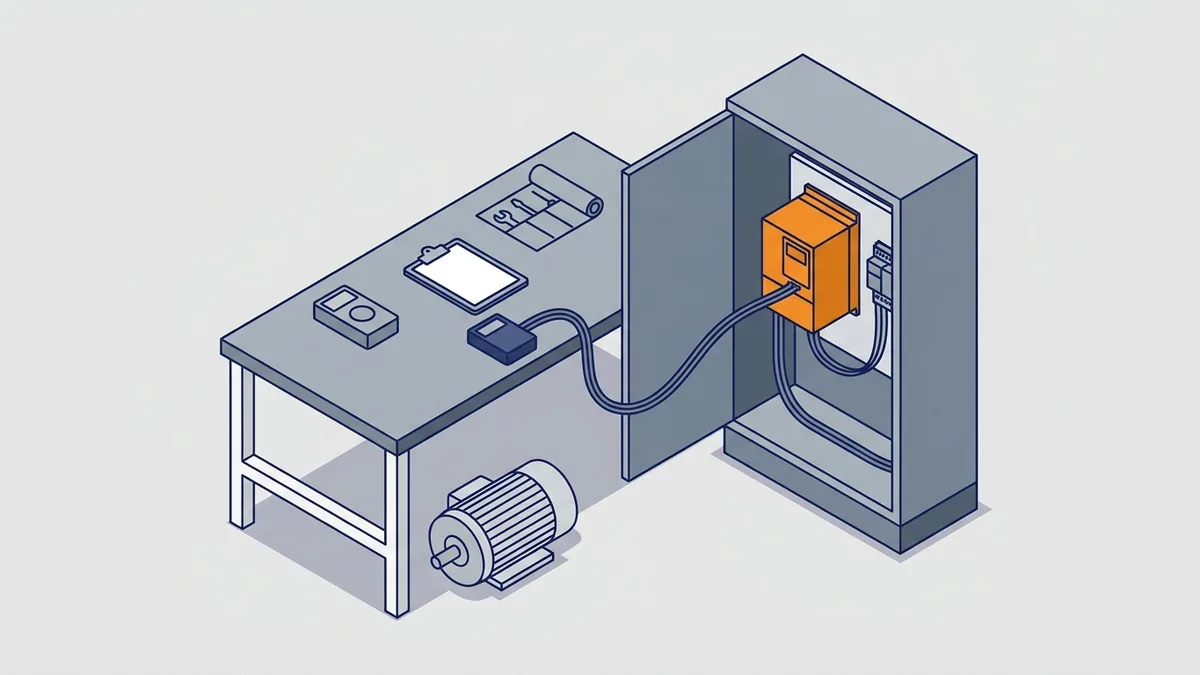
What Parameters Do You Set When Commissioning a VFD?
Work through these steps in order:
- Enter the motor nameplate data: voltage, FLA, base frequency, RPM and poles.
- Set the electronic overload to the nameplate FLA.
- Choose minimum and maximum frequency for your process.
- Set the acceleration and deceleration ramps.
- Pick the control mode: V/Hz for fans and pumps, vector for high starting torque or precise speed.
- Run an autotune if the drive offers one. Autotune measures the motor’s electrical traits so the drive can control it well.
Test, Check and Record Your Motor and VFD Settings
First, bump-test rotation with the load uncoupled where you can. Then run the motor at low, mid and full speed. At each point, check motor current with a clamp meter and measure motor temperature. Finally, record every final parameter. That record lets you set up a spare drive quickly after a failure.
Common Mistakes and Troubleshooting a Motor and VFD
Most problems trace back to a few repeat errors. Fix these, and many nuisance faults disappear.
What Are the Common Mistakes With a Motor and VFD?
- Sizing the drive by horsepower alone instead of FLA.
- Running a standard motor on long leads with no reactor or filter.
- Bonding the cable shield at only one end.
- Using conduit as the motor ground.
- Running a standard fan-cooled motor at low speed under heavy load.
- Setting the electronic overload to the wrong current.
- Routing power and control wiring together.
Typical Drive Faults and First Checks
| Fault | What it usually means | First checks |
|---|---|---|
| Overcurrent | Output current went past the drive’s limit | Acceleration ramp, motor and cable insulation, jammed load |
| Overvoltage | DC bus voltage too high, often while stopping | Deceleration ramp, braking resistor |
| Undervoltage | DC bus voltage too low | Supply voltage, loose connections, lost phase |
| Overload | Motor current above the overload setting too long | Overload setting, load, mechanical binding |
| Overtemperature | Drive running too hot | Cooling fan, airflow, clearances, room temperature |
| Ground fault | Output current is leaking to ground | Motor and cable insulation, wet or damaged cable, motor terminal box |
| Phase loss | The drive lost an input phase or sees an unbalanced output | Fuses, input connections, motor leads, motor windings |
| Short circuit | Output phases are shorted together or to ground | Motor leads, motor windings, drive output stage (power off first) |
Fault names and codes vary by brand. For example, one maker’s overcurrent may show under a different code from another’s. So check the fault code table in your drive manual.
When Is It Safe to Reset a Drive Fault?
Reset a fault only after you know the cause. A one-time overvoltage after a fast stop is usually safe to reset once you lengthen the ramp. However, never keep resetting a ground fault, short circuit or repeated overcurrent. Each reset can send fault current through the output stage and damage the drive.
Instead, remove power and follow the safety steps above. Then disconnect the motor leads from the drive. Test the motor and cable with a megger, and look for damage. If both test well, power up the drive with the motor disconnected to see whether the drive itself faults.
Why Does a VFD Fault on Overvoltage When Stopping?
When the drive slows a heavy load quickly, the motor acts as a generator. That energy flows back into the DC bus, and the bus voltage climbs until the drive trips. To fix it, lengthen the deceleration ramp. If you need fast stops, add a braking resistor sized from the drive manual.
Failure Points Inside the Drive
Inside the drive, common failures include the DC bus capacitors, the input rectifier and the output IGBTs. Overload can also cause failure. Do not keep resetting a fault that repeats. Instead, check the motor, cable and load first, because the root cause often sits outside the drive.
When to Repair, Replace or Call for Help With a Motor and VFD
Not every failure means new equipment. The right choice depends on what failed and why.
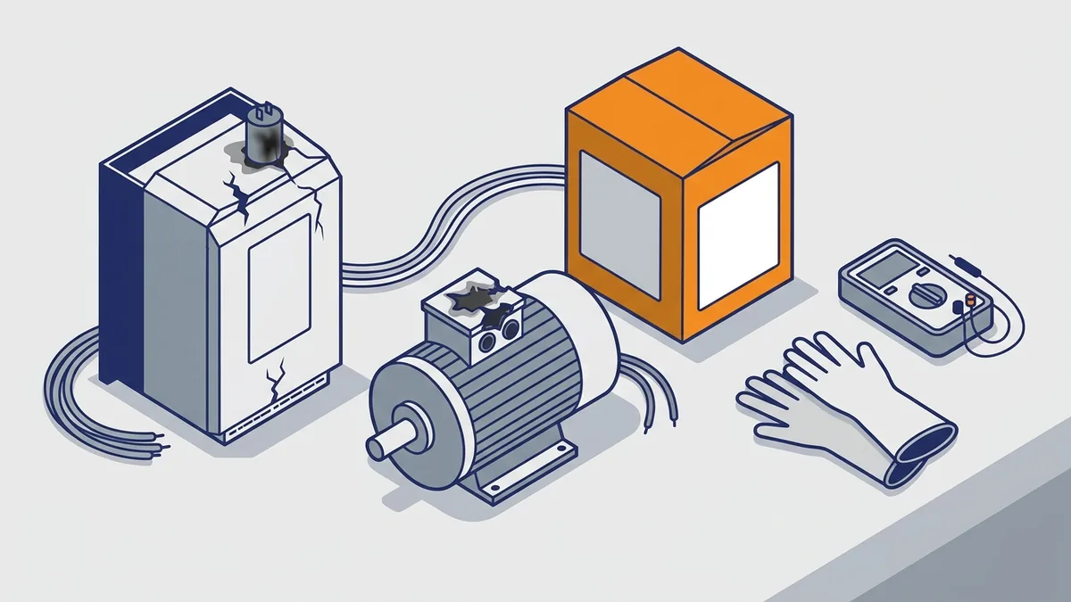
When Should You Repair the Drive or Motor Instead of Replacing It?
Repair a drive when it has a capacitor, IGBT or rectifier failure. Likewise, repair or rewind a motor when you find insulation or bearing damage. In both cases, find the cause first, such as long leads or poor grounding. Otherwise, the failure will likely come back.
When to Replace or Call a Qualified Person
Replace the drive when the model is obsolete or the motor has changed. Also, call a qualified person for medium-voltage work or when the motor nameplate is missing.
Where Do You Find the Manual for Your Drive?
Start with the drive maker’s website. For Eaton drives, find manuals at Eaton.com/drives. For Rockwell drives, search the Rockwell Automation Literature Library. If you cannot find yours, ask Precision Electric to help.
What to Have Ready When You Call About a Motor and VFD
- Drive model and serial number
- Motor nameplate data
- Fault code
- Supply voltage
- Load type, such as a fan, pump or conveyor
- Cable length from drive to motor
You can also browse our Eaton VFD drives page or ask about our repair service.
Frequently asked questions
How does a VFD work on a motor?
The drive’s rectifier converts incoming AC to DC, and the DC bus capacitors smooth it. Then the inverter switches it into PWM pulses that act as AC at your commanded frequency and voltage. Motor speed follows that frequency (speed = 120 × frequency ÷ poles). Also, the drive raises and lowers voltage with frequency to keep torque.
How do I size a VFD for a motor?
Size by the motor’s nameplate FLA, not horsepower. The drive’s continuous output current must be at least the FLA after derating for temperature, altitude and carrier frequency. Next, check the duty rating, variable or constant torque. Use the drive manual for fuse sizing and derating.
How do I wire a VFD to a motor?
Connect the supply to L1/L2/L3 (or R/S/T) and the motor leads to U/V/W. Run a dedicated ground from motor to drive and a continuous ground from drive to utility ground. Use shielded VFD cable bonded at both ends, and keep power and control wiring apart. Always torque terminals and follow the drive’s installation manual.
What does a VFD do for a motor?
A VFD varies motor speed by changing the supply frequency and voltage. It also controls acceleration and deceleration, with less starting stress than across-the-line starting. Unlike a soft starter, it keeps controlling speed while the motor runs.
Do I need an inverter-duty motor on a VFD?
Not always, but the motor insulation must survive the drive’s voltage spikes. Current NEMA MG 1 Part 31 sets the limit for motors rated 600 V and below at 3.1 × rated line-to-line voltage, with rise times of 0.1 µs or longer. Standard motors on long leads may need a reactor or dV/dt filter. So check the motor maker’s lead-length limits.
Can a VFD run a DC motor?
No. A VFD makes variable-frequency AC for AC motors. Instead, a DC motor needs a DC drive, which uses an SCR bridge for variable armature voltage. Speed follows armature voltage, and torque follows armature current.
A motor and VFD perform best when you treat them as one system. Size the drive on FLA, protect the motor insulation, ground and shield the cable at both ends, and set parameters from the nameplate. When the drive manual and other sources disagree, follow the manual. If you need help choosing, wiring or repairing your motor and drive, contact Precision Electric for a quote or repair, or browse our drive products.