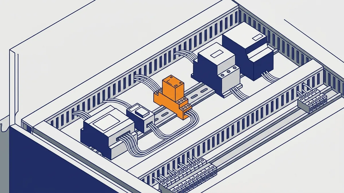









Servo Motors Explained: Types, Operation and Fault Finding
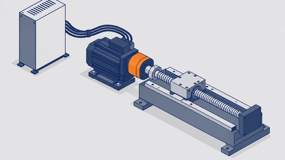
Servo motors drive the machine axes, robots and positioning systems that keep a plant running, but the name covers everything from a 9 g hobby servo to a large industrial motor with its own drive. So when one fails or you need to specify a new one, you first need to know what you are dealing with. This guide explains how servo motors work, the main types, how to size one, and how to find a fault before you buy a replacement.
On this page
- What is a servo motor?
- How does a servo motor work?
- What is inside a servo motor system?
- Servo motor vs stepper motor vs standard motor
- Types of servo motors
- Small servo motors and the SG90 micro servo
- Where servo motors are used
- How to choose and size servo motors
- Wiring, setup and tuning basics
- What do I need to match when replacing a servo motor?
- Which feedback protocol must match: EnDat, Hiperface, BiSS or resolver?
- Which cables and connectors must match?
- Encoder alignment and cabling
- Tuning after the mechanics check out
- How do I start tuning a servo?
- What are the signs of an unstable servo loop?
- Common servo motor problems and troubleshooting
- How do I discharge the drive’s DC bus safely?
- How do I tell whether the motor, encoder, cable or drive is at fault?
- How do I test the motor electrically?
- How do I check that the brake releases and holds?
- What do fault codes mean on my brand of drive?
- Why does my servo motor overheat?
- Bearing wear and noise
- Encoder faults
- How do I replace an absolute-encoder battery without losing position?
- Servo motor maintenance
- Repair or replace servo motors?
- Where to find servo motor manuals, datasheets and software
- Frequently asked questions
What is a servo motor?
A servo motor is a motor paired with a feedback device and run by a servo drive or controller in a closed loop. The feedback device, most often an encoder (a sensor that reports shaft position), tells the drive where the shaft actually is. Then the drive compares that with the command and corrects any difference. As a result, the motor holds a commanded position, speed or torque, even when the load pushes back.
If you searched “what is servo motor,” the short answer is the same: it is a motor that checks its own work. A standard motor just turns when you apply power. By contrast, a servo keeps measuring its motion and adjusting until it matches the target.
What are servo motors, really? A system, not a motor type
The word “servo” describes the control loop, not how the motor is built. Any motor with closed-loop feedback that responds to disturbances in its motion counts as a servo motor. So servo motors can use a brushed DC, brushless DC or AC permanent magnet motor underneath. For that reason, it helps to think of a servo motor system: motor, feedback, drive and controller working together.
Industrial servo motors vs hobby servos
Two very different products share the name. First, industrial servo motors connect to a separate drive, also called an amplifier, with an encoder or resolver for feedback and a motion controller giving commands. Second, hobby and RC servos pack a small motor, a gearbox, a potentiometer and a control board into one plastic case. Both close a loop, but they differ in power, accuracy and fault reporting. Throughout this guide, we say clearly which one we mean.
What does a servo motor do?
A servo motor moves a load to a precise position and holds it there. Along the way, it controls speed and acceleration so the move is smooth and repeatable. In addition, it corrects errors all the time, so a bump or a load change does not leave the axis out of place. In practice, a servo can:
- Move to a commanded position and stop on target
- Hold position under load
- Follow a set speed or acceleration profile
- Limit or control torque, such as for pressing or tensioning
How does a servo motor work?
Servo motors work by comparing what you asked for with what actually happened, then closing the gap. In an industrial system, this happens thousands of times per second. Here is the basic loop:

- First, the motion controller sends a command for position, speed or torque.
- Next, the servo drive powers the motor to start the move.
- Then the encoder or resolver reports the actual position or speed back to the drive.
- After that, the drive compares the actual value with the command. This difference is the error.
- Finally, the drive adjusts motor current to shrink the error, and the cycle repeats.
Cascaded loops: position, speed and current
Most industrial drives stack several loops inside each other. The outer position loop turns position error into a speed command. Next, the speed loop compares commanded speed with the speed calculated from encoder feedback. It then adjusts the torque command sent to the inner current loop. Because current sets torque, the current loop is how the drive actually pushes the load.
Proportional control: a hard push for big errors
A servo drives hard when the error is large and gently when it is small. For example, a shaft with a long distance to turn runs at full speed, while one close to the target runs slower. As the error drops toward zero, the motor eases onto the target instead of slamming into it. Real drives add more control terms on top of this, and tuning sets how strongly each one acts.
Semi-closed vs fully closed loop
In a semi-closed loop, the encoder sits on the motor shaft. So the drive knows where the motor is, but it assumes the screw, belt or gearbox follows perfectly. In a fully closed loop, a linear encoder or a load-side encoder reads the machine position directly. For example, the drive can take feedback from an encoder on a lead screw or drive pulley. As a result, it can correct backlash (play in gears or screws) and belt stretch, at the cost of more setup.
How do servo motors work in a hobby servo?
Hobby servo motors use the same idea on a smaller scale. A potentiometer, which is a variable resistor, turns with the output shaft and reports its angle. Then the onboard control board compares that angle with the pulse width of the incoming signal. If the two differ, it drives the motor until they match.
What is inside a servo motor system?
What parts make up a servo motor system? It has four core parts plus the network that links them. Each one has a job, and a fault in any of them can look like a motor problem.
- Servo motor: turns current from the drive into shaft torque.
- Servo drive (amplifier): powers the motor and runs the control loops.
- Feedback device: an encoder or resolver that reports position and speed.
- Motion controller: a PLC, motion card or CNC control that sends commands.
- Communication bus: the network or wiring that carries commands and status between controller and drive.
Feedback devices: encoders, resolvers and tachometers
An optical encoder is the most common feedback device on servo motors. It reads a coded disc with light and sends position data to the drive. A resolver, by contrast, is a rugged rotary transformer that handles heat and vibration well. However, a tachometer reports speed only, so it cannot close a position loop on its own.
Absolute encoders remember position through a power cycle, so the axis does not need to find home after start-up. Some use a battery to keep that memory. When the battery dies, the drive can lose position or throw an alarm. That cheap fix often looks like a much bigger failure.
Holding brakes
Many servo motors carry an optional holding brake, typically 24 VDC and mounted at the rear of the motor. It holds the load in place when power is off, such as on a vertical axis. In normal use, it holds a stopped load rather than stopping a moving one. Also, if the brake does not release, the motor fights it and can overheat or fault.
How a servo drive differs from a VFD
A servo drive works on the same basic principle as a variable frequency drive (VFD). It converts AC to DC, then back to a controlled output for the motor. On top of that, it reads encoder feedback, adjusts its output in real time and talks to the motion controller. So you cannot swap in a general-purpose VFD and expect servo performance.
Servo motor vs stepper motor vs standard motor
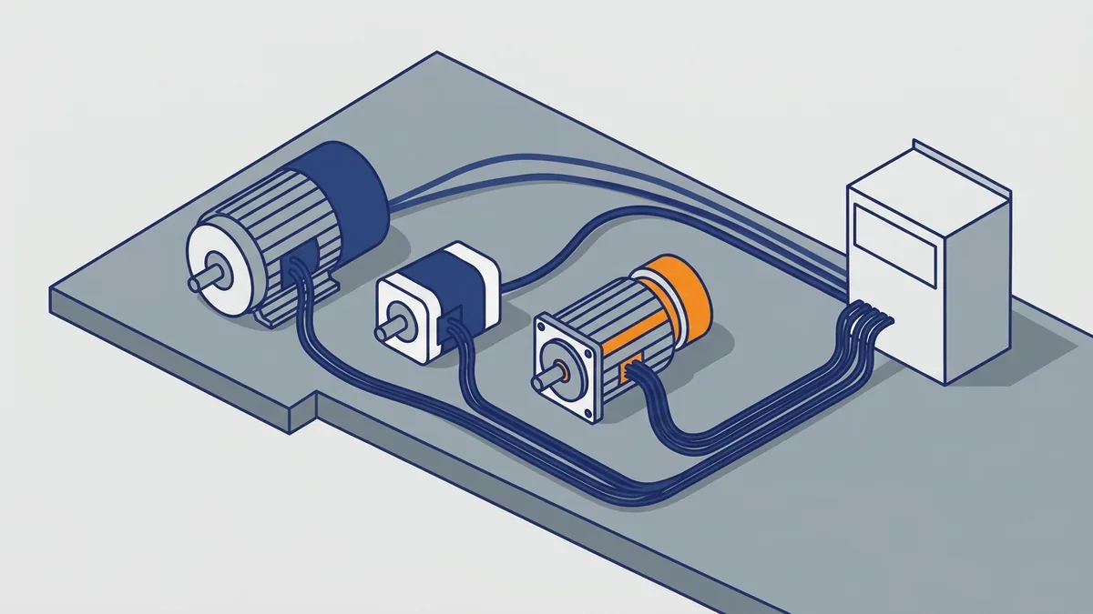
All three turn electrical power into shaft motion. The difference is how much each one knows about where the shaft is, and how hard it works to keep it there. The table sums up the main points.
| Feature | Standard motor | Stepper motor | Servo motor system |
|---|---|---|---|
| Feedback | Usually none | Often none (open loop); closed-loop versions exist | Always (encoder, resolver or potentiometer) |
| Positioning | Not designed for it | Moves in fixed steps; can miss steps under load | Corrects position errors continuously |
| Tuning | None | No feedback tuning in open loop | Loop tuning needed |
| Cost | Lowest | Relatively low | Usually higher |
| Typical fit | Fans, pumps, conveyors | Light, predictable positioning | Precise, repeatable motion under changing loads |
What is the difference between a servo motor and a stepper motor?
A stepper moves in fixed steps and often runs open loop, with no feedback encoder. That keeps cost down, and there is no feedback loop to tune. However, if the load is too heavy, the motor can miss steps and the controller will not know. A servo motor, by contrast, measures its position and corrects errors, so it tracks the command even when the load changes.
Closed-loop steppers blur the line. They add an encoder to a stepper, and they have grown in popularity for jobs where missed steps are a concern.
When should you choose servo motors?
A servo motor system typically costs more than a stepper system because of the feedback sensor and processing electronics. Even so, servo motors are the usual choice when you need high confidence that the axis will follow the command closely. For example, high speeds, changing loads and tight positioning all favor a servo. Meanwhile, a standard motor fits jobs that just need to run, such as fans and pumps.
Types of servo motors
Because “servo” names a control system, the motor underneath can be one of several types. The three main industrial types are brushed DC, brushless DC (BLDC) and AC permanent magnet. Each uses a different commutation method, meaning the way current switches between windings to keep the rotor turning. As a result, they differ in efficiency, maintenance, smoothness and performance.
| Type | Commutation | Strengths | Trade-offs |
|---|---|---|---|
| Brushed DC | Mechanical, carbon brushes on a copper commutator | Low initial cost, strong low-speed torque | Brush and commutator wear and maintenance |
| Brushless DC (BLDC) | Electronic, often with Hall-effect sensors | No brush wear, higher speeds, compact | More complex drive |
| AC permanent magnet | Electronic, sinusoidal, with encoder or resolver feedback | Smooth motion; common on industrial axes | Needs higher-resolution feedback and a matched drive |
What is a servo motor DC? Brushed DC servo basics
People searching “servo motor dc” usually mean a DC servo motor: a DC motor run in a closed loop by a servo drive. In a brushed DC servo, carbon brushes ride on a copper commutator to switch current mechanically. Meanwhile, the servo drive uses feedback to correct speed and position. A brushed motor with an encoder is the classic budget positioning option.
Brushed DC servos offer low initial cost and strong torque at low speed. However, the brushes and commutator need regular inspection and replacement, which raises lifetime cost. For example, ADVANCED Motion Controls cites about 3,000 hours of life for a brushed motor at 100% duty, versus over 10,000 hours for brushless. Treat that as one vendor’s figure, not a rule for every motor.
Brushless DC servo motors
Brushless DC servo motors switch current electronically, using an external controller and Hall-effect sensors (small magnetic position sensors) instead of brushes. So there is no brush or commutator wear and no sparking at a commutator. They are also more efficient and can be more compact than brush motors of similar output. In addition, they reach far higher speeds with less torque drop-off.
The trade-off is a more complex drive. Also, sinusoidal brushless control needs higher-resolution rotor feedback, typically from a shaft-mounted encoder or resolver. Our separate post on brushless servo motors goes deeper on selection and repair.
Is a brushed or brushless DC servo better?
Neither wins every time. A brushed DC servo suits budget-limited positioning, low speeds and older machines built around one. Brushless, on the other hand, suits high duty cycles, higher speeds and closed-loop precision work. When you compare cost, include the drive price with the brushed motor, because you are buying a motor-and-drive system. Allied Motion’s guide to choosing between brush and brushless DC motors walks through this comparison.
What is an AC servo motor?
An AC servo motor is usually an AC permanent magnet motor run by a servo drive with encoder or resolver feedback. Its windings take sinusoidal current, which gives smooth torque and fine control at low speed. That makes AC servo motors common on industrial machine axes, robots and packaging equipment. Compared with BLDC, they use a different commutation method and need higher-resolution feedback.
Kollmorgen’s blog on DC vs AC servo motors compares all three types side by side. For brand-specific details, see our posts on Baldor, Fanuc and Allen-Bradley servo motors.
Small servo motors and the SG90 micro servo
Small servo motors come in two very different forms, so start by knowing which one you have. The SG90 sits at the hobby end. Compact industrial servos sit at the other.
What is a small servo motor?
A small servo motor can mean a hobby or RC micro servo, like the 9 g SG90, with the motor, gears, potentiometer and control board in one case. It can also mean a compact industrial servo that still runs with a separate drive and an encoder. The first takes a simple pulse signal from a microcontroller. In contrast, the second needs a matched drive, setup and tuning, and it reports faults.
What is an SG90 micro servo motor and what are its specs?
The SG90 micro servo motor is a Tower Pro hobby servo of about 9 g, with plastic (POM) gears and roughly 180° of travel. It runs on 4.8 to 6 V and takes a 50 Hz PWM (pulse-width modulation) signal. However, published specs disagree between sellers and datasheet copies, so the table shows ranges.
| Spec | Published range |
|---|---|
| Supply voltage | 4.8 to 6 V (do not exceed 6 V) |
| Stall torque | About 1.2 to 2.5 kg·cm, by source and voltage |
| Speed | About 0.08 to 0.12 s per 60° |
| Travel | About 180°; some batches about 120° |
| Weight | About 9 g; some listings up to 14.7 g |
| Signal | 50 Hz, about 1 ms (0°) to 2 ms (180°) pulses |
| Current | About 10 mA idle, 100 to 250 mA moving, up to about 650 mA at stall |
Tower Pro has an official product page for the SG90 at towerpro.com.tw. It lists 9 g, 1.8 kg/cm stall torque at 4.8 V, 0.1 s/60° speed, 4.8 V operating voltage and a POM gear set. Still, units and seller sheets vary, so verify your unit against the datasheet from your seller, and test it with your real load if torque matters.
How do I wire and power an SG90 servo motor?
The SG90 servo motor has three wires, usually brown for ground, red for +5 V and orange for signal. Wire order varies by manufacturer, though, so check the connector keying and your seller’s sheet before you plug it in. Many units use a 3-pin JR-style connector. Then connect the signal wire to a PWM-capable pin on your board.
Power is where most problems start. A 3.3 V rail is not enough, because one source reports the servo makes only about 30% of its normal torque there. Also, a moving or stalled servo can draw more current than a board’s 5 V pin can supply. If your board resets or browns out, run the servo from a separate 5 V supply and tie its ground to the board ground.
Why is my SG90 jittering, weak or not reaching full angle?
Most SG90 complaints trace back to power, signal or the unit itself. Check these first:
- Jitter or board resets: usually a weak or shared supply. Move to a separate 5 V supply with a common ground.
- Weak torque: check the voltage first, since 3.3 V gives a fraction of normal torque. Also, make sure the load suits plastic gears.
- Short travel: some batches reach only about 120°, so test the range before mounting. In addition, check that your pulses span about 1 to 2 ms.
- No movement: confirm the wire order, since colors and pin order vary.
When to move from a small servo motor to an industrial servo
The SG90 has plastic gears, handles light loads only and has no industrial feedback or fault reporting. That makes it fine for pan-tilt camera mounts, small robot arms and model aircraft control surfaces. However, it is not built for production machines. If the job needs repeatable accuracy, real torque, duty ratings or fault alarms, use an industrial servo with a matched drive.
Where servo motors are used
Servo motors show up wherever motion must be precise and repeatable. The feature that matters most changes with the job:

- Machine positioning axes: these rely on accurate positioning and on holding position under process loads.
- Lead screws and belt drives: speed and position control move carriages smoothly. Load-side encoders can also correct backlash and stretch.
- Robotics: each joint needs position control plus smooth acceleration.
- Vertical axes: holding position matters, often with a 24 VDC brake for power-off.
- Pressing, tensioning and winding: torque control keeps force or tension steady.
- Hobby projects: pan-tilt mounts and model control surfaces use small hobby servos for simple angle control.
How to choose and size servo motors
How do I size a servo motor?
Sizing a servo means proving the motor can handle the whole motion cycle, not just the hardest move. Four checks must all pass:
- Peak torque: the motor’s peak rating must exceed the highest instantaneous torque.
- RMS torque: the thermal average over the cycle must stay below the continuous rating.
- Speed: top speed must stay inside rated speed with margin. One sizing sheet suggests staying within about 90% of rated speed.
- Inertia ratio: load inertia compared with motor inertia must fall within the maker’s limit.
Then check all four against the motor’s speed-torque curve at your actual supply voltage. A low supply voltage shrinks the usable curve at high speed.
Peak torque and RMS torque
Peak torque is acceleration torque plus load torque. Acceleration torque comes from the total inertia (resistance to speed changes) and how fast you speed it up. Load torque, in turn, includes friction, gravity and process forces. So the motor’s peak rating must clear the sum.
RMS torque is the root-mean-square average over the full cycle, including dwell time when the axis sits still. To get it, square each segment’s torque, multiply by its time, add them up, divide by total cycle time, and take the square root. The motor’s continuous rating must be at or above that number. Otherwise, a motor that clears peak but not RMS will overheat on a long shift.
What inertia ratio is acceptable for a servo motor?
The inertia ratio compares load inertia, reflected to the motor shaft, with the motor’s rotor inertia. A high ratio makes the loop harder to tune and can cause overshoot or oscillation. Sources disagree on the limit. Some call 1:1 to 10:1 typical, some allow up to 10:1 for standard installations, and others want 5:1 or less, ideally 3:1.
So there is no single universal rule. Instead, check the motor and drive maker’s sizing guidance for the exact pair you plan to use. In general, fast and demanding moves call for a tighter ratio than slow, less demanding axes.
Gearing and reflected inertia
A gearbox changes how the motor sees the load. Reflected inertia drops by the square of the reduction ratio. For example, a 10:1 gearbox makes the load inertia look 100 times smaller to the motor. As a result, gearing is a common way to bring a high inertia ratio into range, though it adds backlash and its own inertia.
How do I size the matching servo drive and power supply?
The motor is only half the job. The drive and the power supply must also carry the load, so check these items:
- Continuous current: the drive’s continuous rating must cover the motor current at your RMS torque.
- Peak current: the drive must supply the current for your peak torque, for as long as the move lasts. Drive peak ratings are time limited, so check the maker’s duration.
- Bus voltage: the DC bus must be high enough to reach your top speed at the needed torque. However, it must stay within both the drive and motor voltage ratings.
- Supply power: add up the power of the axes that run at the same time, then allow margin. Also check the drive’s allowed input voltage range, since a low supply shrinks the speed-torque curve.
How much regenerative energy do I need to handle?
When a motor slows a load, the load pushes energy back into the drive. A lowering vertical axis does the same. That energy raises the DC bus voltage. The bus capacitors absorb some, but if the voltage climbs too far, the drive trips on bus overvoltage.
A braking resistor (also called a shunt or regen resistor) burns off the extra energy as heat. To size it, estimate the energy in each deceleration from the load’s moving energy, minus friction losses. Then work out the average power over the whole cycle. Choose a resistor that handles both the peak and the average, and use the drive maker’s resistor tables. On multi-axis machines, a shared DC bus lets one axis feed another, which can cut the need for resistors.
Other selection checks
Beyond the four sizing checks, confirm these before you order:
- Feedback type and resolution your drive supports (incremental, absolute or resolver)
- A holding brake if the axis is vertical or must hold with power off
- Mounting flange, shaft size and keyway
- Drive compatibility, including cables and connectors
- Environment, such as heat, dust or washdown
Wiring, setup and tuning basics
A correctly sized motor can still run badly if the drive setup does not match it. Most setup trouble comes down to three areas: motor data, feedback and tuning.
What do I need to match when replacing a servo motor?
When you replace servo motors, the drive settings must match the new motor’s nameplate and parameters. That includes rated current, voltage, encoder type and resolution, and brake wiring. Also check that the mounting, shaft and connectors match the old motor. Some drives must re-read or re-enter motor data even for an identical part, so follow the drive maker’s manual.
For example, a Schneider BCH servo can show a “NonePMFound” fault after a swap. Causes include a motor parameter mismatch, encoder cable damage or encoder failure. In that case, check the encoder connections and confirm the drive configuration matches the nameplate.
Which feedback protocol must match: EnDat, Hiperface, BiSS or resolver?
The drive must support the exact feedback type on the motor. A drive that reads one protocol cannot read another, even if the plug fits. Here are the common types:
- Resolver: an analog device. Check the drive’s resolver input, plus the excitation and pole-pair match.
- EnDat: a digital serial protocol from Heidenhain. It comes in versions, so check which one your drive supports.
- Hiperface: a Sick-Stegmann protocol that combines analog sine and cosine signals with a serial channel.
- BiSS: an open serial protocol. Check that your drive supports your variant.
- Brand-specific serial encoders: many makers use their own protocol, so a motor from one brand often needs that brand’s drive.
Also match whether the encoder is single-turn or multi-turn, and its resolution. In addition, check the encoder supply voltage, since it differs between types.
Which cables and connectors must match?
Do not assume a plug that fits is wired the same. Check the pinout, the shielding and the connector type on both the motor and drive ends. The power cable must also carry the motor current, and a brake needs its own conductors. Long runs can drop voltage at the encoder or brake, so check the maker’s maximum cable length. When in doubt, use the maker’s cable for that motor and drive pair.
Encoder alignment and cabling
The encoder’s commutation offset tells the drive where the rotor magnets sit. If the encoder is misaligned, the drive thinks the shaft is always in the wrong position. As a result, it drives excess torque, and the motor can overheat even with healthy windings and magnets. In addition, inspect encoder cable shielding and connectors, since noise and loose pins cause intermittent faults. On absolute encoders, check the battery too.
Tuning after the mechanics check out
Tune only after you confirm the mechanical side. First, check that couplings are tight, backlash is within spec and the inertia matches what you sized for. Otherwise, you end up tuning around a loose coupling or a binding slide. Then follow the drive maker’s manual and use its tuning software as your starting point.
How do I start tuning a servo?
Before any tuning move, clear the travel path, set travel limits and keep the emergency stop in reach. Then confirm the motor data and the direction of motion. Many drives offer auto-tune, which runs a test move to estimate inertia and set starting gains. It is a good first step.
Auto-tune has limits, though. It can struggle with backlash, a flexible coupling, high friction, a vertical load or a mechanical resonance. The result may be sluggish or noisy, so treat it as a starting point. If you tune by hand, work from the inside out:
- Leave the current loop at the factory setting, since the motor data usually sets it.
- Raise the speed loop proportional gain in small steps until the motor just starts to hum or buzz, then back it off.
- Add speed loop integral action to remove steady error, and keep it modest.
- Raise the position loop gain, which should stay well below what the speed loop can follow.
- Add feedforward if the drive offers it, to cut following error.
What are the signs of an unstable servo loop?
Watch for these signs as you raise gains. They tell you to back off:
- A high-pitched whine, buzz or hum, especially at standstill
- Overshoot or ringing after a move
- The shaft hunting back and forth around the target
- Current or torque readings that swing or look noisy
- Following error that grows instead of shrinking
A steady buzz at one speed often points to a mechanical resonance. In that case, a notch filter in the drive, if available, can help more than lower gains.
Common servo motor problems and troubleshooting
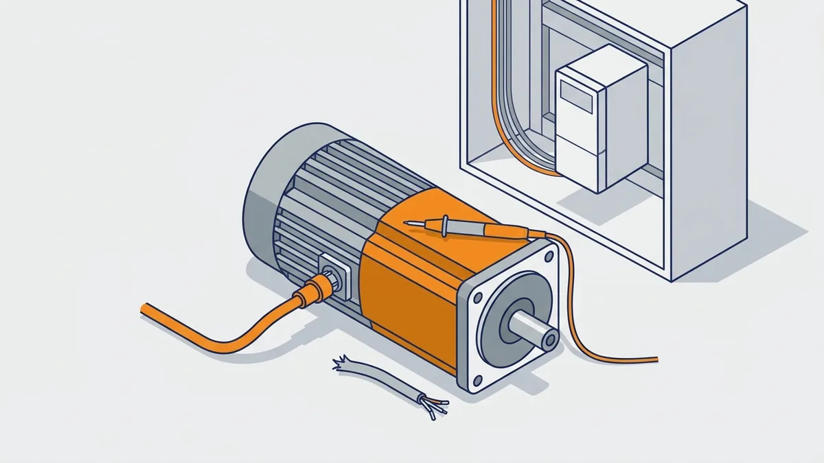
Many suspected motor failures turn out to be encoder, cable, brake, drive or mechanical binding problems. So isolate the fault before you buy a replacement. A following error, listed below, means the gap between commanded and actual position grew too large.
| Symptom | Likely causes | First checks |
|---|---|---|
| Following or position error alarm | Encoder or feedback cable fault, binding, higher load | Encoder cable, shaft turned uncoupled |
| Overheating or thermal fault | Overload, misaligned encoder, dragging brake, loose phase wire, low supply | Which sensor tripped, load, connections |
| Growling, squealing or vibration | Bearing wear, misalignment, contamination | Spin uncoupled, vibration reading |
| Lost position after power-up | Dead absolute-encoder battery, encoder fault | Battery, encoder alarms |
| Fault right after a motor swap | Parameter mismatch, encoder cable or encoder | Nameplate vs drive settings |
How do I discharge the drive’s DC bus safely?
A servo drive stores energy in its bus capacitors, and that energy can stay after you switch off the supply. Lockout/tagout alone does not remove it. So follow these steps before you touch power or motor connections:
- Lock out and tag out the supply to the drive.
- Wait the time printed on the drive label or in its manual. Many makers specify several minutes, and larger drives can need longer.
- Check the drive’s charge indicator, if it has one. However, do not trust a dark light alone.
- Measure the DC bus terminals with a properly rated meter. Proceed only when the reading is at zero or the safe level the maker lists.
Do not short the bus with a tool to drain it. In addition, keep the shaft from turning. A permanent magnet motor makes voltage on its power leads whenever the shaft spins, even with the drive off. Encoder connectors carry low voltage, but handle them only after the power side is safe.
How do I tell whether the motor, encoder, cable or drive is at fault?
Work from the easiest checks toward the motor. Always lock out and tag out the drive and any stored energy before you touch the machine. Then:
- Read the fault code and its time stamp from the drive.
- Inspect the encoder cable and connectors for damage, loose pins or poor shielding.
- Check that the holding brake releases, using the maker’s procedure. Support any vertical load first.
- Uncouple the motor and spin the shaft by hand. Rough or tight rotation points to bearings or internal damage.
- Turn the machine side by hand. If it binds, the motor may be fine.
- Once the machine is safely back in service, compare the running current on the drive display with the nameplate.
If the motor and encoder check out, suspect the drive, cable or mechanics before buying a motor. A repair shop can also confirm the motor on a bench, including encoder pulses on an oscilloscope.
How do I test the motor electrically?
The spin test only finds mechanical trouble. For the windings and brake, first lock out the drive, wait for the bus to discharge and disconnect the motor leads from the drive. Then run these tests:
- Winding resistance: use a low-resistance (milliohm) meter between each pair of phase leads. The three readings should match closely. Compare them with the motor datasheet. An open or much lower reading means a winding fault.
- Insulation resistance: use a megger (insulation tester) from each phase lead to the motor frame. Use the test voltage the motor maker allows, since servo windings can have lower limits than large motors. Compare the result with the maker’s minimum. A low or falling reading points to moisture, contamination or insulation breakdown.
- Brake coil resistance: measure across the brake leads with the brake disconnected. Compare the reading with the datasheet value. An open circuit means a failed coil, and a very low reading suggests a shorted one.
Never megger with the drive or encoder connected, because the test voltage can destroy their electronics. Also keep the encoder and thermal sensor leads out of the test.
How do I check that the brake releases and holds?
Support any vertical load first, and use the maker’s procedure and datasheet values. The checks below cover the main points:
- Voltage: measure at the brake terminals on the motor, with the brake energized. Long cables drop voltage, so a good supply reading can hide a low voltage at the motor. Check the maker’s tolerance, which is often about 10% around the rated voltage.
- Release: with the drive disabled, energize the brake. You should hear or feel it release, and the shaft should turn freely by hand.
- Timing: the datasheet lists release and engage times, usually in milliseconds. Set the controller to wait until the brake has released before it commands motion. On a vertical axis, also let the brake engage before the drive disables.
- Holding torque: with the brake de-energized and the motor uncoupled, apply torque slowly with a torque wrench up to the rated holding value. The shaft must not slip.
Remember that a holding brake is not a stopping brake. Repeated stops from speed wear it out.
What do fault codes mean on my brand of drive?
Fault codes belong to the drive maker, and the same number can mean different things on different brands or even different series. So do not trust a code list from another brand. Write down the exact code and the drive model, then read the fault or troubleshooting chapter in that drive’s own manual.
Allen-Bradley, Fanuc, Yaskawa, Siemens and Mitsubishi each publish these manuals on their support sites. For example, Siemens SINAMICS drives keep faults and alarms in a separate list manual. Also note the drive’s fault history, since earlier codes often show the real cause.
Why does my servo motor overheat?
Start with the fault code and identify which sensor tripped. A drive heatsink fault points to the drive, its cooling or its load. A motor thermistor fault (a temperature sensor in the windings) points to the motor side. Also look for related faults logged around the same time, such as overcurrent or bus overvoltage. Common causes include:
- A duty cycle that exceeds the motor’s RMS rating
- A misaligned encoder making the drive push excess current
- A brake that drags or does not fully release
- A loose motor phase connection, which causes current spikes that read as thermal faults
- A supply at the low edge of the drive’s range, which raises current and heating
- Blocked airflow or dirty cooling fins
ADVANCED Motion Controls’ article on servo drive and motor overheating covers this process in more detail.
Bearing wear and noise
Bearing deterioration is the most common servo motor problem, and it usually warns you with sound. Listen for growling, squeaking or screeching, and watch for rising vibration. Causes include misalignment from poor installation, contamination and overloading. Act early, because failed bearings can throw the encoder out of alignment and lead to overheating. In turn, overheating can break down winding insulation, cause an earth fault and damage magnets.
Encoder faults
The encoder is the most fragile part of most servo motors. Typical problems include a loose cable, a contaminated disc, intermittent encoder power and a dead absolute-encoder battery. Fault codes differ by brand, so look up yours in the drive maker’s manual. Because encoder faults can mimic a dead motor, rule them out before you order a replacement.
How do I replace an absolute-encoder battery without losing position?
Battery type and voltage vary by brand and model. So read the motor or drive manual for the exact part, and do not guess. Then plan the swap so the encoder never loses its memory:
- Write down the current axis position and any offset values, and have the new battery ready.
- Stop the machine and press the emergency stop. Support any vertical load.
- Keep the drive’s control power on if your manual says so. Many makers rely on that power to hold position while the battery is out.
- Swap the battery quickly, with the correct polarity.
- Clear the battery alarm as the manual describes, then confirm the position reading did not change.
If the encoder did lose position, you must re-home the axis. Clear the encoder alarm, then run the maker’s absolute-position setup or homing procedure. Next, check the result against a known mechanical reference. Finally, test with slow moves before you return to production.
Servo motor maintenance
How do I maintain a servo motor?
Good maintenance catches small problems before they take out the encoder or windings. Lock out the equipment before any hands-on inspection. Then build these checks into your schedule:
- Brushed DC motors: inspect brushes for wear and the commutator for scoring or burning.
- Temperature: track running temperature and investigate any rise.
- Vibration: take regular readings with a vibration meter to spot bearing wear early.
- Cooling: keep fins, fans and airflow paths clear of dust and debris.
- Cables: inspect encoder and power connectors, and check cable flex points on moving axes.
- Bearings: replace them at the first signs of noise, before they damage the encoder or cause overheating.
Also, keep a log of fault codes. A rising count of the same alarm often points to a cable or bearing that is starting to fail.
Repair or replace servo motors?
Should I repair or replace a servo motor?
Repair makes sense when the motor is still the right size for the job and the failure is a bearing, encoder, brake or winding. Typical repair work includes bearing replacement, encoder repair, rewinding and alignment correction. On the other hand, replacement makes more sense when the motor is obsolete, undersized for the load, or the repair cost comes close to new. If an axis has always run hot, resize it rather than repair the same motor again.
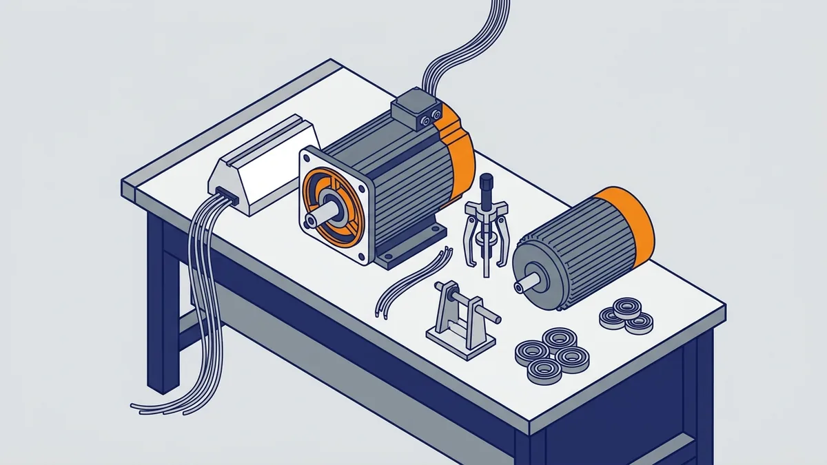
Our separate posts cover brand-specific repair and replacement for Allen-Bradley, Fanuc and Electrocraft/Reliance servo motors. We also have a general guide to AC and DC servo repair.
What to send with a motor for repair
Good information speeds up diagnosis and cuts guesswork. With the motor, send:
- Full nameplate data, or a clear photo of the nameplate
- Drive make and model
- Fault codes and when they occur
- Symptoms such as noise, heat, vibration or lost position
- A note on whether the brake and encoder cable are included
What does servo repair or replacement cost?
Cost depends on frame size, feedback type, brand and whether the drive must change too. Because of that wide range, we do not list typical figures here. Instead, send your nameplate data and symptoms to a repair shop for a quote on your actual motor.
Where to find servo motor manuals, datasheets and software
Where do I find servo motor manuals, datasheets and tuning software?
For any spec you will design around, use the motor maker’s datasheet and the drive maker’s manual. The drive maker also supplies the configuration and tuning software for its drives, usually through its support or downloads area. Avoid relying on wiki pages, patents or blogs for ratings.
For background reading, these vendor resources are useful:
- Anaheim Automation’s Servo Motor Guide, for basics and components
- Kollmorgen’s blog on DC vs AC servo motors, for comparing types
- ADVANCED Motion Controls’ article on brushed vs brushless motors
- ADVANCED Motion Controls’ article on servo drive and motor overheating
- Allied Motion’s guide to choosing between brush and brushless DC motors
For the SG90, start with the Tower Pro product page at towerpro.com.tw, and check the datasheet from your seller, since specs vary between sources.
Frequently asked questions
What is a servo motor?
A servo motor is a motor combined with a feedback device, usually an encoder, and run by a servo controller or drive in a closed loop. That lets it hold a commanded position, speed or torque. It also corrects for disturbances, such as a sudden change in load.
How does a servo motor work?
The controller sends a command, the drive powers the motor, and the encoder or resolver reports actual position or speed. Then the drive compares the two and adjusts motor current to reduce the error, thousands of times per second. A hobby servo does the same with a potentiometer and a small control board.
What does a servo motor do?
It moves a load to a precise position, holds it there, and controls speed and acceleration along the way. That is why servo motors run machine axes, robots and other motion that must be accurate and repeatable.
What is the difference between a DC servo motor and a brushless servo motor?
A brushed DC servo uses brushes and a commutator, so it costs less up front but needs brush maintenance. A brushless servo switches current electronically, with no brush wear, higher speeds and a more complex drive. Both need feedback to work as a servo.
What are the SG90’s basic specs?
The SG90 is a 9 g hobby micro servo for 4.8 to 6 V with about 180° of travel. It uses a 50 Hz PWM signal with roughly 1 to 2 ms pulses and has plastic gears. Published torque figures range from about 1.2 to 2.5 kg·cm depending on the datasheet, so verify your unit.
How do I know if the servo motor or the drive is bad?
Check the fault code first, then lock out the machine and inspect the encoder cable and connector. Next, confirm the brake releases and the shaft turns freely when uncoupled. If the motor and encoder check out, suspect the drive, cable or mechanical binding before buying a motor.
Servo motors are closed-loop systems, so a fault or sizing problem can sit in the motor, encoder, cable, brake, drive or the machine itself. Once you know how the loop works and how to size and check each part, you can choose the right servo and avoid buying a motor you did not need. If you need help diagnosing a fault, a repair quote or a replacement servo, contact Precision Electric and our team will help you get your axis running again.