








What Is a Relay? How It Works, Ratings and Types Explained
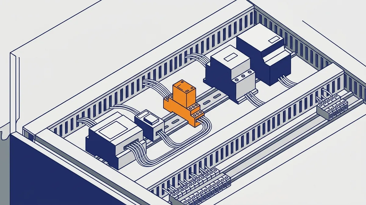
If you have opened a control panel and wondered what is a relay, you have met one of the most common control parts. This guide explains what a relay does in a circuit, how it works, and how to read its coil and contact ratings. You will also learn about timing, latching and RIB relays, plus how to choose, troubleshoot and replace one.
On this page
- What is a relay?
- What does a relay do in a circuit?
- How does a relay work?
- How do relays operate? The electromechanical relay sequence
- What is a relay made of?
- Contacts: common, normally open and normally closed
- Pick-up, drop-out and why a coil needs the right supply
- Contact bounce and arcing
- How much should you derate contacts for motors, solenoids and lamps?
- How do you wire a relay or socket?
- Does a relay coil need a flyback diode, snubber or varistor?
- Types of relays
- What is a time delay relay (timing relay)?
- What is a latching relay?
- What is a RIB relay?
- How to choose a relay
- Common relay mistakes and troubleshooting
- When to replace, repair or call for help
- Frequently asked questions
What is a relay?
A relay is an electrically operated switch. A small control signal switches a separate, larger circuit on or off. In other words, it works like a remote-controlled switch for your load.
There are two main kinds. First, an electromechanical relay uses a coil and moving contacts. In contrast, a solid state relay (SSR) uses semiconductors and has no moving parts. Whichever kind you have, the basic idea stays the same, and this guide covers both.
Relay meaning: the control side and the load side
Every relay has two sides. First, the coil, or input, is the control side. Next, the contacts, or output, are the load side that switches the device you want to run. Because the two sides are separate, the whole idea comes back to one point: a small signal controls a bigger circuit.
The term also covers several product families. For example, general-purpose control relays, timing relays, latching relays and enclosed packages such as RIB relays all count. Each one has its own section below. So whatever type is on your nameplate, you can jump straight to it.
What does a relay do in a circuit?
In plain terms, a relay lets a small signal control a larger load. For example, a programmable logic controller (PLC) output, sensor or pushbutton sends a little current to the coil. Then the contacts switch a motor starter coil, light or heater on a separate circuit.
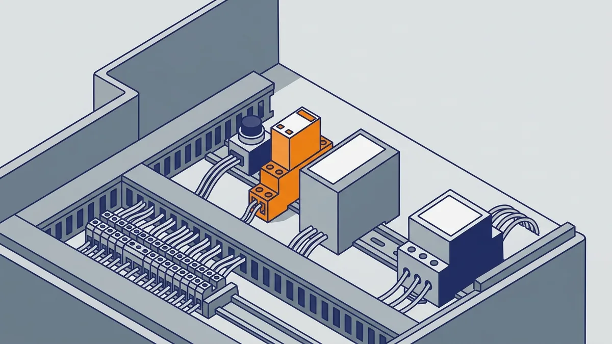
Beyond on and off, a relay gives you three useful effects. Together, they are the practical answer to what a relay is used for.
What is a relay used for? Three jobs it does at once
Relays handle three jobs at the same time:
- Amplification: A relay coil may use only a fraction of a watt. Yet the contacts it operates can carry hundreds of times that power.
- Isolation: There is no electrical path between the coil and the contacts. As a result, a low-voltage controller can switch a load at a different voltage.
- Multiplication: One coil and armature can operate more than one set of contacts. So one signal can switch several circuits.
Why do circuits use a relay instead of a direct switch?
A direct switch must carry the full load current and sit in the load circuit. That would put heavy wiring and the load voltage at your operator panel or controller. Instead, a relay switch keeps the heavy current and higher voltage inside the panel. As a result, a low-voltage controller output can run a higher-voltage load, as long as the contacts are rated for it.
Also, a relay lets one control signal switch several circuits at once. In addition, it keeps the controller output electrically separate from the load. That separation is a big reason this part matters so much in control work.
Typical jobs in a plant
- A PLC or drive output driving a motor starter coil
- Switching lighting or HVAC loads from a building automation system
- Sensing the voltage fed to a load, so a controller knows the load has power
- Interlocking, where one circuit must be off before another can run
Together, these jobs are the plant-floor answer to what a relay is used for. However, drive relay outputs are a topic of their own. For that detail, see our separate post on the Lenze SMVector open collector and relay outputs.
How does a relay work?
An electromechanical relay has two main parts: an electromagnet coil and a set of contacts. When you energise the coil, its magnetic field pulls a movable iron arm called the armature. The armature then makes or breaks the connection with fixed contacts.
In practice, the same short chain of events happens every time the coil turns on or off. Once you can picture it, the device becomes something you can test.
How do relays operate? The electromechanical relay sequence
- Your controller applies voltage to the coil terminals.
- Current flows through the coil winding.
- The current builds a magnetic field in the iron core.
- The field pulls the armature toward the core.
- The armature moves the contacts. Normally open contacts close, and normally closed contacts open.
- Next, the controller removes the voltage, and the magnetic field collapses.
- Finally, the return spring pulls the armature back, and the contacts return to their normal state.
A solid state relay follows the same idea with no armature. Instead, its input circuit does the job of the coil. Its output circuit does the job of the contacts.
What is a relay made of?
- Coil: a winding of insulated wire that becomes an electromagnet when current flows.
- Core: the iron piece inside the coil that concentrates the magnetic field.
- Armature: the movable iron part that the field pulls in and that moves the contacts.
- Return spring: the spring that pushes the armature back when the coil turns off.
- Contacts: the metal points that make or break the load circuit.
If you can name these five parts, you can explain the device to anyone on your crew.
Contacts: common, normally open and normally closed
What do normally open, normally closed and common mean on a relay? “Normal” means the de-energised state, the way the relay sits on a shelf with no circuit connected. A normally open (NO) contact is open at rest and closes when the coil energises. In contrast, a normally closed (NC) contact is closed at rest and opens when the coil energises.
The common (C or COM) terminal is the shared, moving side of the NO and NC contacts. Together, the three terminals form a changeover contact. When the coil energises, it breaks the common-to-NC path and makes the common-to-NO path.
Part numbers describe contacts with pole and throw shorthand. A pole is one separate switched circuit, and throw is the number of positions each pole can reach. For example, enclosed relay listings describe parts as 10 A SPDT, 20 A DPDT or 30 A DPST.
| Code | Meaning | What it does |
|---|---|---|
| SPST | Single pole, single throw | Turns one circuit on or off |
| SPDT | Single pole, double throw | One changeover: C to NO or C to NC |
| DPST | Double pole, single throw | Turns two circuits on or off together |
| DPDT | Double pole, double throw | Two changeover contacts on one coil |
Pick-up, drop-out and why a coil needs the right supply
What are pick-up and drop-out on a relay coil? Makers rate relays separately for coils and for contacts. Pick-up is the minimum coil voltage or current that makes sure the armature moves. Drop-out is the highest value at which the return spring wins and the relay goes back to its normal state.
Drop-out sits well below pick-up. Once the armature pulls in, it needs less coil current to hold it there. So the coil current must fall a long way before the relay releases. As a side note, the terms date from early relays that used gravity, not a spring, to return the armature.
This is why the coil supply matters. First, match the coil voltage and waveform, AC or DC, to your supply. Next, read the full coil code, including the operating range and the coil current or power. Otherwise, a relay that looks right may chatter (buzz on and off), fail to pull in, or overheat.
In short, a full rating has two parts: the coil and the contacts.
Contact bounce and arcing
Contacts behave differently on a real load than on a test bench. For one, they can bounce briefly as they close. Also, breaking a load current can draw an arc across the opening contacts.
That bounce and arcing is what wears contacts over time. Because of this, manufacturers rate contacts for different load types, and you may need to derate them (use them below their full rating). So check the contact rating for your actual load, not just the amp number on the case. Contact wear is the part of the story that shows up in your repair log.
How much should you derate contacts for motors, solenoids and lamps?
No single percentage fits every relay. Makers publish separate contact ratings for resistive, inductive, motor and lamp loads. So find the rating for your load type on the datasheet, and do not use the resistive amp number for a motor or lamp.
Inrush, the brief surge when a load starts, shows why the ratings differ:
- Motors: starting current is often about six times running current.
- Tungsten lamps: a cold filament can draw roughly 10 to 15 times its running current.
- Solenoids: pull-in current is higher than holding current. Also, breaking an inductive coil causes strong arcing.
- DC inductive loads: a DC arc is harder to put out than an AC arc. As a result, DC ratings are lower than AC ratings at the same voltage.
If the datasheet has no rating for your load, pick contacts rated well above the inrush. Otherwise, step up to a contactor. When you are unsure, ask the maker or Precision Electric before you order.
How do you wire a relay or socket?
Pin numbers and terminal marks vary by model. So start with the diagram printed on the relay body or the socket, and trust it over any general rule. Still, a few marks are common.
- Coil: many DIN-rail and plug-in relays mark the coil terminals A1 and A2.
- Contacts, IEC style: 13 and 14 are a normally open pair, and 21 and 22 are a normally closed pair. On a changeover contact, 11 is usually common, 12 is NC and 14 is NO.
- Coil polarity: an AC coil has no polarity. A DC coil usually takes positive on A1 and negative on A2, and this matters most when the relay has a built-in LED or diode.
Then follow this order:
- Read the diagram and match each pin to its terminal on the socket.
- Wire the coil to the control supply, with the right polarity for a DC coil.
- Wire the load through the common terminal and either NO or NC.
- Add the fuse or breaker your design calls for.
- Insert the relay, restore power and test the coil and the load.
Does a relay coil need a flyback diode, snubber or varistor?
Often, yes. When you switch off a coil, its collapsing magnetic field creates a voltage spike. That spike can damage a PLC output or a transistor, and it can also cause electrical noise. A suppressor across the coil absorbs it.
DC coils: use a flyback diode in parallel with the coil. Wire the cathode (the striped end) to the positive side. Pick a diode with a reverse voltage rating above your supply and a current rating above the coil current. However, a diode slows drop-out, so the contacts open a little later.
AC coils: a diode will not work on AC. Instead, use an RC snubber (a resistor and capacitor in series) or a varistor across the coil. Choose a varistor with a voltage rating above the peak supply voltage. For an RC snubber, use the values the relay maker lists.
Also, many sockets and plug-in modules already include a diode, snubber or varistor. So check before you add a second one.
Types of relays
What are the different types of relays? The easiest way to sort them is by what they do. General-purpose, machine tool and reed relays switch with moving contacts. In contrast, solid state relays switch with semiconductors.
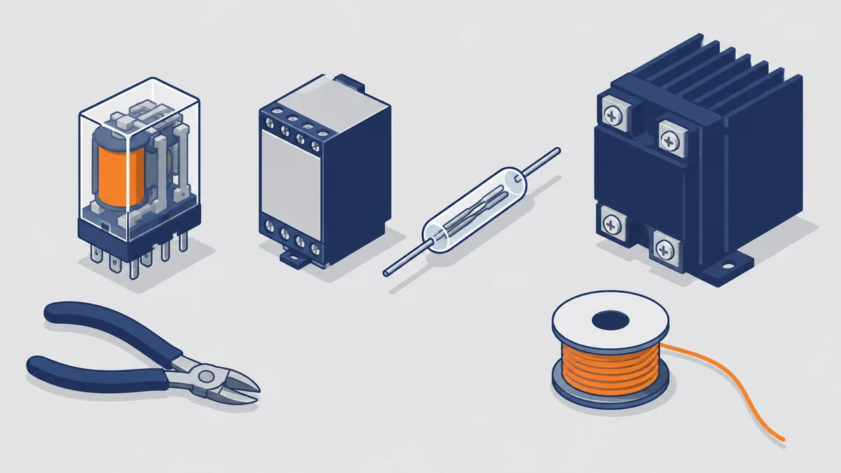
Time delay and latching relays add a function on top. One waits before switching, and the other holds its state without coil power. So the answer depends a little on which family you are holding.
Electromechanical relays
An electromechanical relay (EMR) is the classic coil-and-contacts design. It comes in three major subgroups: general purpose, machine tool and reed relays. When most technicians picture a relay, this is the device they see.
Strengths:
- Several contact sets can run from one coil.
- Closed contacts have a very low voltage drop.
- A large momentary overload is less of a problem than for an SSR.
- In general, EMRs handle higher currents and voltages than SSRs.
- Upfront cost is lower than for an SSR.
Weaknesses:
- Moving parts and arcing wear the contacts.
- Response is slower, about 5 to 15 milliseconds.
- Each operation makes an audible click.
Solid state relays
A solid state relay switches the load with semiconductor switches such as triacs, thyristors or MOSFETs. On the input side, an optocoupler (a light-based isolator) usually separates the control from the load. Because there are no moving parts, nothing clicks or wears from motion.
- Speed: it responds in under 100 microseconds, about 100 times faster than an EMR.
- No bounce: the output does not bounce when it switches.
- Silent: there is no click.
- High-cycle use: with no wearing moving parts, it suits jobs that switch often.
However, SSRs have limits too:
- Higher on-resistance makes significant heat while on, so mount them on a heatsink (a finned metal block that draws heat away).
- Most have only one output, while EMRs can have several.
- They cannot handle a large momentary overload the way an EMR can.
- Upfront price is higher.
So if you need a relay that never clicks, the answer is usually an SSR.
How do you size an SSR heatsink?
An SSR turns part of the load power into heat. A rough estimate is the output voltage drop times the load current. Many AC SSRs drop around 1 to 1.5 volts, so a 20 A load can make roughly 20 to 30 watts of heat. Check your datasheet for the real drop.
Then follow these steps:
- Find the maximum case or base temperature on the datasheet.
- Subtract the hottest ambient temperature in your panel.
- Divide that difference by the heat in watts. The result is the heatsink thermal resistance you need, in degrees per watt, or lower.
- Add a safety margin, because panels run hot.
Also, read the maker’s derating curve. Most SSRs must carry less current as ambient temperature rises. Finally, mount the SSR flat on the heatsink with thermal compound, and leave room for airflow.
Zero-cross vs random turn-on SSRs, and SSR leakage current
What do zero-cross and random-turn-on SSRs do? A zero-cross SSR waits until the AC waveform passes near zero volts, then turns on. As a result, it makes less inrush and less electrical noise, which suits resistive loads such as heaters. A random-turn-on SSR switches on right when you apply the input, at any point on the waveform. So it suits inductive loads and phase control.
Next, leakage. An AC SSR passes a small current even when it is off, because its output circuit is not a true open gap. That current can keep a small load, such as a low-power lamp, an LED or a PLC input, partly on or glowing. To fix it, place a resistor across the load to carry the leakage current, and size the resistor from the datasheet leakage value. Because of this leakage, never treat an off SSR as an isolated circuit when you work on a load.
Solid state vs electromechanical: which to choose
What is the difference between a solid state relay and an electromechanical relay? An EMR moves metal contacts with a magnetic coil, while an SSR switches with semiconductors. Both fit the basic definition; they just switch in different ways.
| Feature | Electromechanical | Solid state |
|---|---|---|
| Switching | Coil and moving contacts | Semiconductors |
| Response | 5 to 15 ms | Under 100 microseconds |
| Bounce and noise | Bounce and click | None |
| Outputs | Often several | Usually one |
| Overload and heat | Tolerates surges, little heat | Less tolerant, needs heatsink |
| Upfront cost | Lower | Higher |
Here is a simple rule. Choose an SSR for fast or frequent cycling, such as factory automation. Instead, choose an EMR when you need several poles, higher current, overload tolerance or low cost. Also, in high-cycle jobs, the lack of contact wear can make an SSR cheaper over its service life.
What is a time delay relay (timing relay)?
A time delay relay is a control relay with a timer built in. A basic relay changes its contacts the moment the coil energises. In contrast, a time delay relay changes its output only after a preset time.
Think of it as a standard relay plus one more piece: time. Its output can be a mechanical relay contact or a solid state output. Also, timing ranges run from less than one second to many days, depending on the model.
Is a timing relay the same as a time delay relay? Yes, it is. Timing relay, timer relay and time delay relay all name the same device.
Time delay relay functions
What is the difference between on-delay and off-delay? The short answer is when the wait happens. On-delay waits before turning on, while off-delay waits before turning off.
On-delay (delay on make): Timing starts when you apply control voltage. When the delay runs out, the output energises. Removing power resets the timer. Typical uses are sequential motor starting, conveyor staging and limiting inrush current, the brief surge when a load starts.
Off-delay (delay on break): The output turns on as soon as the trigger arrives. Then, after you remove the trigger, it stays on for the set time before turning off. Other names include delay on release and TOF. Typical uses are fan run-on and pump run-on.
One warning applies to off-delay timers with a separate trigger input. Control power must stay on during the timing period. Removing the trigger signal is not the same as losing the supply. If the supply drops out, the timer may lose power and drop its output early.
Interval, one-shot and other timing functions
- Interval: the output energises at once and stays on for a limited time.
- One-shot (single shot): a trigger gives one fixed-length output pulse. A retriggerable one-shot restarts its timing with each new trigger.
- Repeat cycle: the output turns on and off over and over, starting with either an off or an on period.
- On/off delay: combines a delay on turn-on with a delay on turn-off.
- Pulse generator and memory latch: extra functions that some manufacturers also list.
Each function is a different way to time the same basic switching action. However, function names, letter codes and numbers vary by manufacturer. So always check the timing diagram on the datasheet before you wire or set the relay.
Choosing and setting a timing relay
How do I choose and set a timing relay? Start with the job the timer must do. Then work through this checklist:
- Function: on-delay, off-delay, interval, repeat cycle or another.
- Timing range: the range must include your setpoint.
- Trigger type: timing starts when power is applied, or on a separate trigger input.
- Output contacts: number, arrangement and rating, and whether the output is mechanical or solid state.
- Supply voltage: the value, and whether it is AC or DC.
- Power interruption: what the relay does after the supply drops and returns.
For repeat-cycle timers, check two more points. First, does the first period start ON or OFF? Second, can you adjust the on time (T1) and off time (T2) separately?
Also, a timing relay is still a relay underneath. So match its coil and contacts just as you would on any other one.
Timing examples: star-delta start and blower run-on
A star-delta starter is a classic on-delay job. The timer holds the star contactor in until the motor nears speed, and one example sets about 5 seconds. When the delay ends, the starter drops star and brings in delta.
An HVAC blower is a classic off-delay job. After the gas valve closes, an off-delay of 60 to 90 seconds keeps the blower running. As a result, the blower clears leftover heat from the heat exchanger.
What is a latching relay?
What is a latching relay and how does it work? A short pulse sets it (ON) or resets it (OFF). After the pulse ends, it keeps its contact position with no coil power until it gets the opposite pulse. You may also see it called a keep relay, bistable relay or impulse relay.
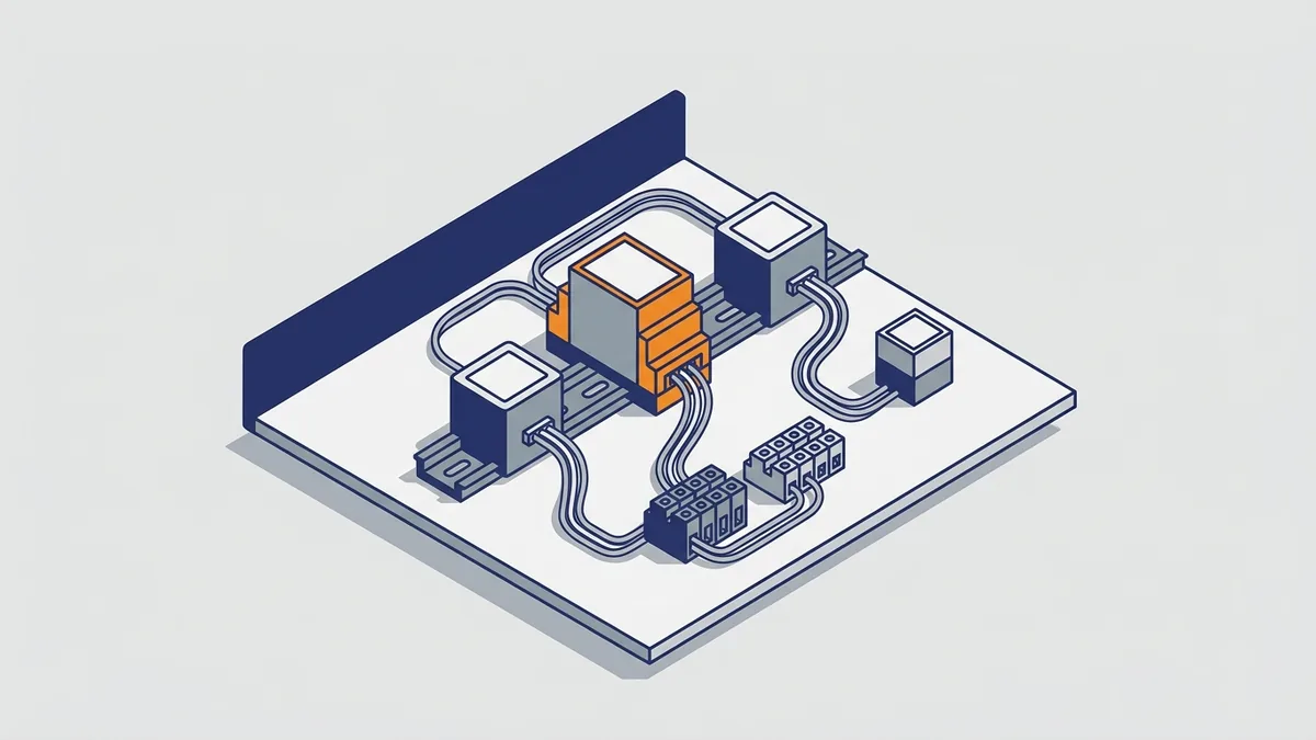
Here is how it works inside. A pulse on the coil moves the armature to the set position. Then a magnet or a mechanical latch holds it there. Later, a second pulse, on a reset coil or with reversed polarity, releases it.
People choose latching relays for three reasons. First, a magnetic latching coil draws power only during the set or reset pulse. Second, there is no coil heat in continuous service. Third, the contacts keep their state through a power interruption.
So if you need a device that remembers its last state, this is it. For more detail, the Omron Industrial Automation General Purpose Relays FAQ explains how latching relays set, reset and hold.
Single-coil vs dual-coil latching relays
- Dual coil (double winding): a pulse on the set coil operates the relay, and a pulse on the reset coil releases it.
- Single coil (single winding): a pulse of one polarity sets the relay, and a pulse of reversed polarity resets it.
- Holding method: either magnetic or mechanical, depending on the design.
How do you reset a latching relay? For a dual-coil type, send a short pulse to the reset coil. With a single-coil type, apply a pulse of reversed polarity to the same coil. Reversing the voltage can be harder than just switching power off, so plan your control wiring for it.
Also, give each pulse enough voltage and enough time, as the datasheet states. If the set or reset voltage is too low, the relay may fail to operate. Worse, it may not recover by itself when the supply comes back. With latching types, reset wiring is where the basic picture changes most.
Latching relay vs a latching (seal-in) circuit
Is a latching relay the same as a latching (seal-in) circuit? No. People also call a standard relay wired with a holding contact a latching or seal-in circuit. However, its coil stays powered the whole time the circuit is latched, so it unlatches if power drops.
A true latching relay holds its position with no coil power. After a power loss, it keeps its last state. That difference changes how a machine behaves on restart, which makes it one of the most practical points in this guide. Start/stop seal-in logic is a separate topic, and we cover it in a narrower post.
What is a RIB relay?
RIB stands for Relay In a Box, a product line from Functional Devices. The relay comes mounted and pre-wired in an enclosure. So you do not have to buy a relay, socket, rail and enclosure separately and put them together.
For many building and HVAC technicians, a RIB is the hardware they picture when someone says “relay.”
RIB Pilot series and other enclosed control relay options
The RIB Pilot series targets building automation systems, HVAC, low-horsepower motor and lighting control. Pilot models such as the RIBU1C, RIBU2C, RIBH1C, RIBH2C and RIBH1S have 10 A contacts. You use them to control light loads, to drive larger power relays or contactors, or to sense the voltage fed to a load.
The wider RIB line includes other versions. For example, distributor listings show these:
- Power relays: RIB12P, listed as 20 A DPDT with a 12 VAC/VDC coil, and RIB01P30, listed as 30 A DPST (2NO) with a 120 VAC coil.
- Dry contact relay: RIB02BDC, listed as 20 A SPDT with a 208-277 VAC coil.
- Latching relay: RIBL24B, listed as a 20 A latching RIB relay at 24 VAC/DC.
- Override switch: RIB2401SB, listed as 20 A SPST-NO with a 24 VAC/DC or 120 VAC coil and an override switch.
- RIBT series: physically separate entrances for coil and contact wiring, to keep high and low voltage apart.
Also, RIB contact wires exit through a 1/2 in or 3/4 in NPT nipple, a short threaded pipe fitting.
How to read a RIB part number like RIBU1C
Take the RIBU1C as an example. Listings describe it as a 10 A SPDT pilot relay with a 10-30 VAC/VDC or 120 VAC coil. They also show it in a NEMA 1 enclosure, a general indoor type. In plain terms, it has one changeover contact rated 10 A.
However, do not guess ratings from the letters in the code. Before you order a replacement, confirm the contact type, coil voltage and current rating on the Functional Devices datasheet. Ratings differ by model, and distributor listings can be out of date. Reading a listing this way turns the part into a parts list you can check.
How to choose a relay
How do I choose the right relay? Work through these points in order. Also, write down each answer before you look at catalogs.

- Load type and voltage: a resistive heater, an inductive load such as a motor or solenoid, or lighting, plus whether the load is AC or DC.
- Load current: the running current plus any inrush at start.
- Contact arrangement: how many poles, and whether you need NO, NC or changeover contacts.
- Coil voltage: the value and whether the supply is AC or DC.
- Function: basic, timing or latching.
- Mounting and enclosure: plug-in socket, DIN rail (a standard mounting rail), panel mount, or an enclosed relay such as a RIB.
- Environment: temperature, dust, moisture and vibration where the relay will live.
Keep the coil side and the contact side separate, because makers rate them independently. A relay can have the perfect coil and still be wrong for the load, or the other way around. That split is the heart of the matter for buyers.
When the contacts are too small for the load
Sometimes a relay is not the right part. If the load current or inrush goes beyond the contact rating, step up to a heavier device. For large motor loads, that often means a contactor, so check the manufacturer’s guide for how it rates its contactors. For very fast or frequent switching, an SSR may suit the job better.
That is also why pilot relays, such as the RIB Pilot series, often drive a contactor rather than the load itself. In that setup, the small relay handles the control signal and the contactor handles the heavy current. Knowing these limits is part of a full answer to what is a relay.
When does a load need a contactor instead of a relay?
No single current or horsepower cutoff applies to every relay. Instead, compare your load to the contact rating for that load type on the datasheet. Some relays list a horsepower rating, and others list only amps.
Use a contactor in these cases:
- The motor’s full-load current or horsepower is above the relay’s rating for motor loads.
- The starting current is above what the contacts can make and break.
- The load is a motor that needs overload protection, because contactors pair with overload relays.
- The load switches often, or it is a heavy inductive load that wears relay contacts quickly.
Contactors carry horsepower and amp ratings, and they are built for motor inrush. So the usual setup is a small relay or PLC output driving the contactor coil.
Which standards apply, and when do you need a safety relay?
Marks on the datasheet tell you which standards a relay meets. For example, UL 508 covers industrial control equipment, and UL 916 covers energy management equipment. IEC 60947-5-1 covers control circuit devices, including electromechanical control relays. Which mark you need depends on your panel, your machine and local rules. So ask the authority that inspects your work if you are unsure.
A safety relay is different from a control relay. It uses force-guided contacts, also called positively guided contacts. Their normally open and normally closed contacts are mechanically linked. So if one contact welds, the linked contact cannot change state, and the control system can detect the fault. The standard for these relays is EN 50205.
Use a safety relay when a safety function, such as an emergency stop or guard monitoring, must detect a welded contact. Your risk assessment sets the required safety level. Never use an ordinary control relay for that job.
How much does it cost?
Price depends on the contacts, the coil, the function and the enclosure. For example, a plug-in general purpose relay, an SSR, a multi-function timer and an enclosed RIB relay all sit at different price points. In general, SSRs cost more up front than EMRs, so ask your supplier for a quote with the full part number.
In short, price follows the same three things: coil, contacts and package.
Common relay mistakes and troubleshooting
What are common relay mistakes, and how do I troubleshoot a relay? Most relay problems trace back to a few repeat errors. Each one comes down to a gap in the basics covered above.
- Wrong coil supply: the relay looks right, but the coil voltage or AC/DC waveform does not match the supply.
- Wrong contact rating: contacts rated for a resistive load go on an inductive load, which causes arcing and early wear.
- Mixed-up timing: someone confuses on-delay with off-delay, or expects an off-delay to keep timing after total power loss.
- Latching treated as standard: the control circuit does not send proper set and reset pulses.
- No heatsink on an SSR: the relay overheats because nothing carries away its on-state heat.
Troubleshooting step by step
Before you test anything, follow lockout/tagout and your local codes. Take live readings only if you are qualified and your site rules allow it. Then work through this sequence:
- Coil voltage: check that the correct voltage reaches the coil terminals when the controller calls for it.
- Coil resistance: with power off and isolated, measure across the coil. An open reading points to a failed coil, so compare readings with the datasheet if it lists a value.
- Click or LED: listen for a click or watch the status indicator when the coil energises.
- Contact test: check continuity with power off, or voltage drop across closed contacts on a live circuit where permitted.
- Contact condition: look for pitting, burning or welded contacts.
If the coil gets voltage and the relay clicks but the load does not run, suspect the contacts or load wiring. When the coil has no voltage, look upstream at the controller, PLC output or wiring. Either way, you are splitting the problem in half: coil side and contact side.
What coil readings are normal, and what means good or bad?
Coil resistance varies a lot between models, so there is no universal normal value. Look for the value on the datasheet, which often lists a tolerance such as plus or minus 10 percent at room temperature. If the datasheet is missing, divide the rated coil voltage by the rated coil current to estimate it for a DC coil. AC coils are harder to judge with a meter, so compare with a known good relay of the same part number.
- Within tolerance: the winding is likely good.
- Open circuit or infinite reading: the winding is broken, so replace the relay.
- Far below the listed value: shorted turns are likely, so replace the relay.
Next, pick-up, drop-out and voltage range. Datasheets list the voltage at which the relay must operate and the voltage at which it must release. Many list an operating range around 80 to 110 percent of rated coil voltage, but the numbers differ by model and by AC or DC coil. So read your own datasheet. As a rule, a relay that fails to pull in at the low end of its range, or chatters, has a supply problem or a weak coil.
When to replace, repair or call for help
When should I replace a relay or get help? Replace a failed plug-in relay. It is a wear item, and a new one costs little compared with downtime. Also, match the full part number, or at least the coil code, contact arrangement and contact rating.
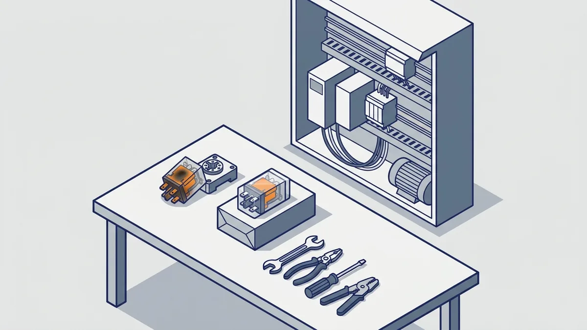
Get help when the same relay keeps failing. Repeat failures usually point to the load, the supply or a drive or PLC output, not the relay itself. In addition, get help with relays in safety circuits and with any part that is obsolete or has an unclear part number.
How long should a relay last?
Datasheets list two life ratings. Mechanical life counts operations with no load on the contacts, and it is often in the millions. Electrical life counts operations at the rated load, and it is much shorter. Because of this, a relay that switches a heavy load often will wear out long before its mechanical life ends. Using the contacts below their rating usually extends their life.
For preventive replacement, count the operations if your controller can. Then replace the relay well before it reaches its rated electrical life, especially in critical circuits. Also replace a relay on these signs:
- Pitted, burned or discolored contacts
- A high voltage drop across closed contacts
- Heat marks on the relay or socket
- Chatter, slow release or a weak click
Precision Electric can help identify drives, controls and related parts, including older relays with worn labels. For more depth, see our narrower posts on drive relay outputs, contactors and PLC outputs. Each one builds on the basics covered here.
Frequently asked questions
What does a relay do?
A relay uses a small control signal to switch a separate, larger circuit on or off. It acts like a remote-controlled switch and keeps the control circuit electrically isolated from the load. That is the short answer to what is a relay in any panel.
How does a relay work?
Voltage on the coil creates a magnetic field. The field pulls an armature that moves the contacts, so normally open contacts close and normally closed contacts open. When the coil turns off, a spring returns the armature and the contacts go back to their normal state.
What does a relay do in a circuit?
It lets a low-power signal from a controller, sensor or switch control a higher-power load on a separate circuit. Also, one coil can operate several contact sets, so one signal can switch several circuits.
What is a time delay relay?
A time delay relay, or timing relay, is a control relay with a built-in timer. It changes its output only after a preset delay. The delay can follow the input being applied (on-delay) or removed (off-delay). Other functions include interval, one-shot and repeat cycle.
What is a latching relay?
A short pulse sets or resets a latching relay. It then holds its contact position with no coil power until it gets the opposite pulse. Single-coil types reset with reversed polarity, and dual-coil types use a separate reset coil.
What is a RIB relay?
RIB means Relay In a Box, a Functional Devices product line. It is a relay pre-mounted and pre-wired in an enclosure. The Pilot series has 10 A contacts for building automation, HVAC, light motor and lighting control, and for driving larger relays or contactors.
Now you have a full answer to what is a relay: a small signal on a coil or input switches a separate, larger circuit. From there, timing relays add a delay, latching relays add memory, and RIB relays add a ready-made enclosure. Match the coil, the contacts and the function to the job, and check the manufacturer datasheet before you order. If you need help identifying a relay, a repair or a quote on a replacement, contact Precision Electric and our team will help you find the right part.