








VFD What Is It? A Plain Guide to Variable Frequency Drives
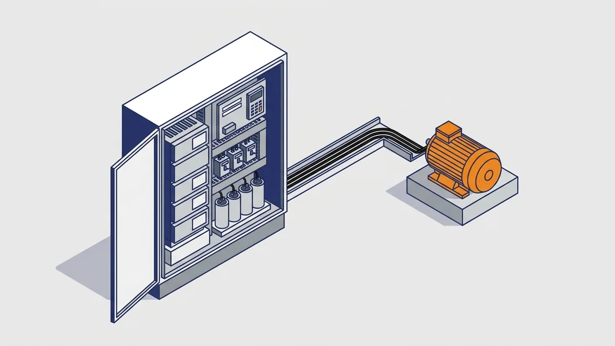
VFD: what is it, and why does almost every new pump, fan and conveyor panel seem to have one? A variable frequency drive sits between the power line and an AC motor, and it lets you set the motor’s speed instead of running it flat out. This guide follows one drive from the incoming line to the motor shaft, then covers energy savings, 12-pulse drives, Modbus control, and when to repair or replace a drive.
On this page
- VFD: what is it? The variable frequency drive explained
- How a VFD works: from line power to motor speed
- Power electronics inside a VFD: what is it built from?
- Why use a VFD drive? Benefits and limits
- How much energy can a VFD save?
- VFD types and what to match to your load
- 6-pulse, 12-pulse and 18-pulse VFDs: harmonics and when 12-pulse is used
- Modbus and VFDs: controlling a drive over RS-485
- How to wire and ground a VFD for EMC
- What do common VFD fault codes mean, and what do I check first?
- Common VFD installation and application mistakes
- Where to find VFD manuals, software and parts
- When to repair, replace or ask for help
- Frequently asked questions
VFD: what is it? The variable frequency drive explained
A VFD is a solid-state power electronics device that controls the speed and torque of an AC motor. It does this by changing the frequency and voltage it sends to the motor. Instead of passing fixed 60 Hz (or 50 Hz) line power straight through, the drive builds a new AC waveform at the frequency you ask for.
What does a VFD do for a motor?
So when you look at a running VFD, what is it doing day to day? In short, it gives the motor the speed the process needs, not just full speed. Most drives also handle these jobs:
- Speed setting from a keypad, an analog signal or a network command.
- Ramps that let the motor speed up and slow down smoothly.
- Soft starting, which cuts the current surge and mechanical shock of a full-voltage start.
- Controlled stopping, either by ramping down or by letting the motor coast.
- Torque or current limiting to protect the machine.
- Motor protection and diagnostics, such as overload trips, fault codes and fault logs.
However, the exact feature set varies by model. For example, torque limiting, built-in PID control and braking options differ between drive families. So check the manual for your specific drive before you count on a feature.
What else is a VFD called?
You will hear many names for the same device. The most common ones are:
- Variable frequency drive (VFD)
- Variable speed drive (VSD)
- Adjustable speed drive (ASD)
- Adjustable frequency drive (AFD)
- AC drive
- Inverter
Also, many people say “VFD drive,” even though the D already means drive. So when a print says AFD or inverter instead of VFD, what is it telling you? In nearly every case, it names the same kind of motor speed controller.
What a VFD replaces
Before drives were common, most motors started across the line and ran at one fixed speed. To cut flow, plants added dampers, valves or inlet vanes that throttle the output while the motor keeps running at full speed. A variable frequency drive replaces that throttling by slowing the motor itself. As a result, the motor draws less power instead of fighting a partly closed valve.
How a VFD works: from line power to motor speed
If you open the cover on a VFD, what is it you are looking at? Every drive follows the same basic path. First, AC comes in, then it becomes DC in the middle, and finally new AC goes out to the motor.
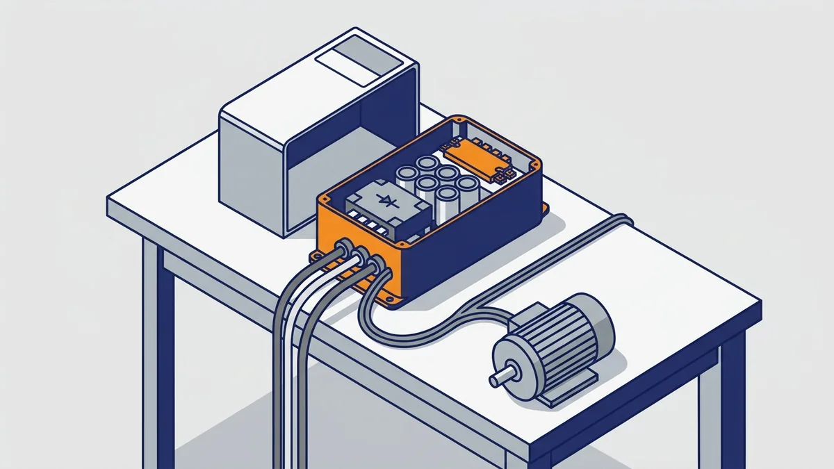
What are the three stages of a VFD?
- Rectifier (converter): turns incoming AC line power into DC. The drive needs a steady DC source before it can build a new waveform.
- DC bus: a bank of capacitors, sometimes with inductors, that smooths and stores the DC. It gives the inverter a stable voltage to switch.
- Inverter: fast transistors switch the DC on and off to make variable-voltage, variable-frequency AC. This stage sets the motor speed.
On top of these stages, a control board, keypad and I/O terminals take your commands. They also run the protection features and store fault history.
How does a VFD control motor speed?
An AC induction motor’s speed follows the frequency of its supply. So when the drive lowers the output frequency, the motor slows down. When it raises the frequency, the motor speeds up. Some drives can output from near zero to 400 Hz or more, but the motor and load set the real limits.
In addition, the drive lowers voltage together with frequency. This keeps the volts-per-hertz ratio (V/Hz) roughly steady, so the motor keeps its magnetic strength and torque at lower speeds. Without that, a slowed motor would draw too much current and run hot.
Where does the speed command come from?
With a VFD, what is it that tells the drive how fast to run? The speed command, called the frequency reference, usually comes from one of three places:
- Keypad on the front of the drive.
- Analog signal of 4 to 20 mA or 0 to 10 V from a PLC, sensor or speed pot.
- Network command, such as Modbus from a PLC or HMI.
Next, you set a parameter that tells the drive which source to follow. Many startup problems come from a drive still watching the keypad while the PLC sends the command.
Power electronics inside a VFD: what is it built from?
Every power electronics VFD design uses the same building blocks, even when the brand and size change. Inside, you will find a rectifier, a capacitor bank with a choke and precharge circuit, IGBT transistors with their gate drivers, a control board, and a heatsink with cooling fans. Here is what each part does and what to watch for when you troubleshoot.
Rectifier (converter) section
The rectifier turns AC into DC. Most general-purpose drives use a six-diode bridge, often called a 6-pulse bridge because it draws current in six pulses per cycle. More advanced drives use controlled thyristors or IGBTs instead. An IGBT input stage goes by the name active front end (AFE).
Because the bridge charges the capacitors to the peak of the line voltage, the DC bus sits higher than the nameplate suggests. For example, one source puts a 480 V drive’s bus at about 650 to 680 V DC, with a peak near 678 V DC. So set your meter to a range that can read it, and use test gear rated for that voltage.
DC bus: capacitors, chokes and precharge
The DC bus is the drive’s energy store. Its capacitors smooth the rippled DC from the rectifier and hold energy for the inverter. Many drives also add a DC choke, which is an inductor that reduces ripple and input harmonics.
Next comes the precharge circuit. Empty capacitors would pull a huge inrush current at power-up, so a resistor or soft-charge circuit fills them slowly. After that, a relay or contactor bypasses the resistor for normal running.
Why is the DC bus dangerous after power is removed? On a powered-down VFD, what is it that can still hurt you? The bus capacitors can hold a lethal charge for some time after you open the disconnect, even with a dark display. So follow the manufacturer’s wait time and voltage-check procedure in the drive manual, plus your site’s lockout and electrical safety rules. Also, if capacitors or fans have failed, see our post on VFD overheating for causes and checks.
How long should I wait, and how do I verify the DC bus is discharged?
First, lock out and tag out the drive’s supply. Then wait the time printed on the drive’s warning label or in its manual. Many drives call for about 5 minutes, but larger drives can need longer, so never assume. Waiting alone does not prove the bus is safe.
Next, measure the bus yourself:
- Wear the PPE your site’s arc flash and shock assessment requires. That usually means safety glasses, insulated gloves and arc-rated clothing.
- Use a meter with a CAT III or CAT IV rating that covers the bus voltage, along with matching leads.
- Test the meter on a known live source, then measure across the DC bus terminals. They are often marked DC+ and DC-, or + and -.
- Also check from each bus terminal to ground, and check the input and motor terminals.
- Confirm the meter again on a known source. Work only when every reading is at or near zero.
If the drive has no bus terminals, the manual shows another test point. In that case, follow the manual.
Inverter section: IGBTs and PWM
In the inverter of a VFD, what is it that sets the speed? The answer is IGBTs (insulated gate bipolar transistors), which are fast electronic switches. They switch the DC bus voltage on and off thousands of times a second.
What is PWM? Pulse width modulation means the drive changes how long each pulse stays on. Wider pulses give a higher average voltage, and narrower pulses give a lower one. Because the motor windings smooth those pulses, the result is a sine-like current that produces torque.
The switching rate goes by the name carrier frequency. One source gives a typical range of 2 kHz to 15 kHz. Most drives let you adjust it, and a higher carrier usually means a quieter motor but more heat in the drive. So check the drive manual for the allowed range and any derating.
Regeneration and braking resistors
Sometimes the load drives the motor instead of the other way around. This happens with an overhauling load, such as a lowering hoist, or when a heavy load slows down quickly. Then the motor turns faster than the speed the drive sets, and it acts like a generator.
As a result, current flows back through the inverter to the DC bus. However, the diode rectifier blocks it from returning to the line, so the bus voltage rises. If it climbs too far, the drive trips on overvoltage.
What is a braking resistor for? It burns off that extra energy as heat. A brake transistor, often called a chopper, switches the resistor in when bus voltage climbs. Other options include a regen unit, which feeds energy back to the line, or an active front end that does the same job. Your choice depends on how often and how hard the load brakes.
Why use a VFD drive? Benefits and limits
Why use a VFD instead of a starter or a damper? A starter runs the motor at one speed, and a damper or valve wastes energy by throttling. A VFD drive changes the motor speed itself. So if you are weighing a starter against a VFD, what is it that tips the decision? Usually, it is one or more of these benefits:
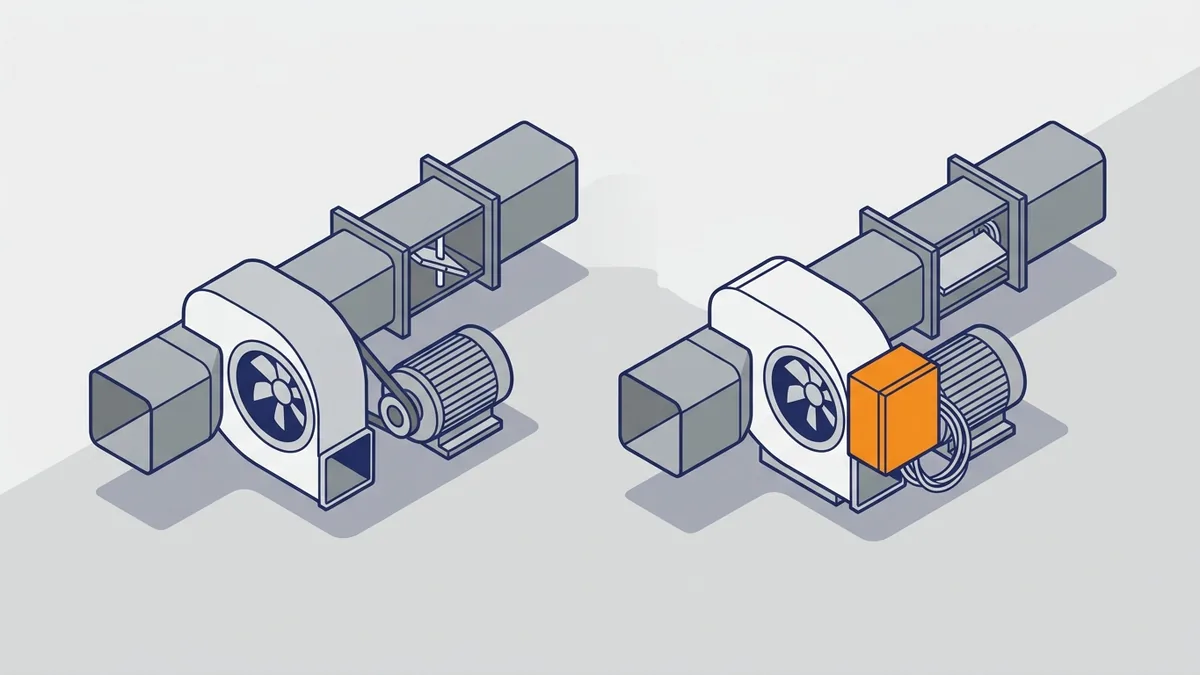
- Energy savings on fans and pumps that often run below full flow.
- Controlled acceleration that protects belts, gears, couplings and product.
- Process control, such as holding a pressure, flow or level setpoint.
- Soft start with lower starting current and less mechanical stress.
- Communications and diagnostics, including fault codes and live data over a network.
Limits of variable frequency drives
Before you add a VFD, what is it going to cost you besides the purchase? Watch for these trade-offs:
- Harmonics: the rectifier draws distorted current that can stress transformers and generators. The 12-pulse section below covers this.
- Heat: the drive loses some energy as heat and needs proper cooling.
- Cost and space compared with a simple starter.
- EMI: fast switching can cause electrical noise in nearby wiring.
- Motor insulation and cables: fast voltage edges stress motor windings, especially on long leads. Use the drive and motor manufacturers’ limits.
For grounding problems and short-circuit trips, see our post on VFD ground faults. For heat problems, see our VFD overheating post.
Is my motor and cable suitable for a VFD?
Maybe, but check first. The drive’s fast voltage pulses can travel down a long cable and add up at the motor, which stresses the winding insulation. Here is what to look at:
- Insulation: choose an inverter-duty motor, which is built for drive-fed use. Many are rated under NEMA MG 1 Part 31. An older standard motor may fail early, especially at 460 V and above.
- Lead length: every drive maker lists a maximum motor cable length. It changes with the drive, the carrier frequency and the motor, so use the manual for yours.
- Output reactors and dV/dt filters: these slow the voltage edges. Add one when leads are long or the motor insulation is unknown. A sine filter goes further for the longest runs.
- Bearing currents: drive-fed motors can pass current through the bearings and pit them. Common fixes are a shaft grounding ring, an insulated bearing and good cable grounding.
When is a soft starter, bypass contactor or EC motor a better choice than a VFD?
A VFD is not always the right tool. If the motor only needs a gentle start and then runs at full speed, a soft starter often does the job. It usually costs less than a drive of the same size and adds no speed control. The table compares the choices.
| Option | Best for | Trade-off |
|---|---|---|
| VFD | Variable speed, process control, savings at part load | Higher cost, harmonics, extra wiring care |
| Soft starter | Fixed-speed loads that need a smooth start or stop | No speed control while running |
| Bypass contactor | Keeping a motor running if the drive or soft starter fails | Adds contactors, interlocks and panel space |
| EC motor | Small fans and blowers that need speed control | Motor and electronics are replaced as one unit |
A typical VFD bypass uses three contactors. One feeds the drive input, one connects the drive output to the motor, and one connects the motor straight to the line. Interlock the output and bypass contactors so line power can never reach the drive output. A soft starter can also use a bypass contactor that closes after the ramp, which cuts heat in the starter.
How much energy can a VFD save?
Energy saving by VFD control on fans and pumps comes from the affinity laws. These rules link speed to flow, pressure and power on centrifugal loads with no static head:
- Flow changes directly with speed.
- Pressure or head changes with speed squared.
- Power changes with speed cubed.
So on a centrifugal fan VFD, what is it worth to slow down a little? A small speed cut gives a big power cut. The table shows ideal values before drive and motor losses.
| Speed | Flow | Pressure or head | Power |
|---|---|---|---|
| 100% (full speed) | Flow: 100% | Head: 100% | Power: 100% |
| 90% | 90% | 81% | 73% |
| 80% | 80% | 64% | 51% |
| 70% | 70% | 49% | 34% |
| 50% | 50% | 25% | 12.5% |
For example, at 80% speed, power drops to about 0.8 × 0.8 × 0.8 = 0.512. That is roughly 49% less instantaneous power. However, these numbers hold only for centrifugal loads without static head, as the next sections explain.
DOE’s worked fan example
The DOE Motor Tip Sheet 11: Adjustable Speed Drive gives a clear example. A 20 shaft-hp exhaust fan needs 16.4 kW at full speed. At half speed, it moves 50% of the airflow and needs only 1/8 of the full-load power.
Next, DOE adds real losses. At that point, motor efficiency is 77.8% and drive efficiency is 86%. Even so, the fan, motor and drive together need only 2.8 kW. Notice that this is more than the ideal 1/8 of 16.4 kW, because losses never go to zero.
Also, DOE notes that PWM drives see the most use on variable torque loads from 1 to 1,000 hp. That is where the cube law does its best work.
Do VFDs save energy on every motor?
No. When you ask whether a VFD will pay off, what is it about the load that matters? Three things count most: torque type, static head and hours at reduced speed.
- Variable torque loads (centrifugal fans and pumps): this is where the big savings live.
- Constant torque loads (conveyors, compressors, positive displacement pumps): the cube law does not apply. Savings come from matching speed to demand and from features like flux optimization, energy-saving modes and advanced vector control.
- Systems with static head: DOE’s Variable Speed Pumping guide calls it a common mistake to use the affinity laws for savings here. With static head, a small speed cut can greatly reduce flow and pump efficiency.
- Full speed all day: a drive that always runs at 100% saves nothing and adds its own losses.
By contrast, in a system that is mostly friction, lowering speed keeps the pump near its best efficiency point. That is why the same drive can save a lot on one pump and little on another.
How do I estimate VFD energy savings for my fan or pump?
To estimate savings from a VFD, what is it you need first? DOE says the key input is the load duty cycle, which is the share of time the equipment runs at each operating point. Then follow these steps:
- Build a load profile with the hours per year at each flow or speed.
- Get the fan or pump curve and the system curve.
- Apply the affinity laws to find power at each point, but only where static head is low.
- Add drive and motor efficiency at part load.
- Weight the power by hours. For kWh, use hp × 0.746 × hours.
- Compare with your current method, such as a damper, at the same points. Then multiply the kWh saved by your electric rate.
For the full method, use DOE Motor Tip Sheet 11, DOE’s Variable Speed Pumping guide, and the Rockwell Automation white paper Energy Savings With Adjustable Frequency Drives. The Rockwell paper shows how to build a fan load profile and a weighted horsepower. Also, ask your electric utility about rebates for drives. Payback depends on your load, hours and rate, so no single figure fits every job.
What does a worked payback calculation look like?
Here is a simple example with assumed numbers, so swap in your own. Take a fan that draws 16.4 kW at full speed and runs at 80% speed for 4,000 hours a year. Power at 80% speed is about 16.4 × 0.512 = 8.4 kW, so the ideal saving is about 8.0 kW.
- Energy saved: 8.0 kW × 4,000 hours = 32,000 kWh per year.
- Money saved at an assumed $0.10 per kWh: 32,000 × 0.10 = $3,200 per year.
- Simple payback: installed cost of the drive project divided by $3,200.
Treat that $3,200 as a ceiling. It compares against full speed, but a damper already saves a little, and drive losses cut the gain further. So compare against your real current method, as the steps above say. We cannot give a reliable typical payback range, because it swings with load, hours and rate. Finally, ask your utility about rebates before you buy, since some programs want approval first.
VFD types and what to match to your load
Most general-purpose drives today are VSI (voltage source inverter) PWM drives. They hold a steady DC bus voltage and use PWM to build the output, as described above. So when a buyer asks about a general-purpose VFD, what is it most likely to be? Almost always, it is a VSI PWM drive.
V/Hz versus vector control
Control mode is how the drive decides what voltage and frequency to send. The two main families are:
- V/Hz (scalar) control: keeps a set volts-per-hertz ratio. It is simple and works well for fans, pumps and several motors on one drive.
- Vector control: uses a motor model to control torque more precisely, especially at low speed. It suits conveyors, mixers, hoists and other demanding loads, with or without encoder feedback.
However, modes and names differ by brand. Check the drive’s programming manual for the modes your model supports.
Matching an AC drive to your load
When sizing a VFD, what is it that most often goes wrong? Picking by horsepower alone. Instead, work through these points:
- Decide whether the load is variable torque or constant torque.
- Size by motor full-load current, not hp alone, because motors of the same hp can draw different current.
- Choose the overload class, such as normal duty or heavy duty.
- Check the environment: temperature, dust, moisture and altitude.
- Pick an enclosure that fits the location.
For a full sizing walk-through, see our 3 Phase Motor VFD guide. For fan and pump drives in buildings, see our HVAC VFD buying guide.
How do I size and protect a VFD?
Start with the overload rating, because it shows how much extra current the drive can give for a short time. Many drives list two ratings. For example, a common pattern is normal duty at about 110% of rated current for 60 seconds, and heavy duty at about 150% for 60 seconds. Normal duty suits fans and pumps. Heavy duty suits conveyors, crushers and other loads with hard starts. The exact numbers differ by model, so read the rating table.
Then check these items:
- Temperature and altitude derating: drives have a maximum ambient temperature, and most need a lower current rating above it. Many also need derating above about 1,000 m (3,300 ft). The manual gives the curve.
- Input fusing: use the fuse or breaker type and size the manual lists. Some drives require fast semiconductor fuses.
- Short-circuit current rating (SCCR): compare the drive’s SCCR with the fault current available at the panel. A panel is only as strong as its weakest part.
- Line reactor: an AC line reactor on the input, often about 3% impedance, helps when the supply is stiff, when capacitor banks are nearby, or when you want less harmonic current. The manual says when it is needed.
6-pulse, 12-pulse and 18-pulse VFDs: harmonics and when 12-pulse is used
A standard 6-pulse front end does not draw smooth sine-wave current. Instead, it draws current in pulses, and that distorted current carries harmonics. Harmonics are currents at whole multiples of the line frequency, and they can heat transformers and upset generators and other loads.
The harmonic orders follow a simple rule: h = kq ± 1, where q is the pulse number and k is 1, 2, 3 and so on. For a 6-pulse bridge, that gives the 5th, 7th, 11th and 13th. Of these, the 5th and 7th are the largest. Sources put untreated 6-pulse current distortion anywhere from about 35% up to 80%, depending on conditions.
What is a 12-pulse VFD and how does it work?
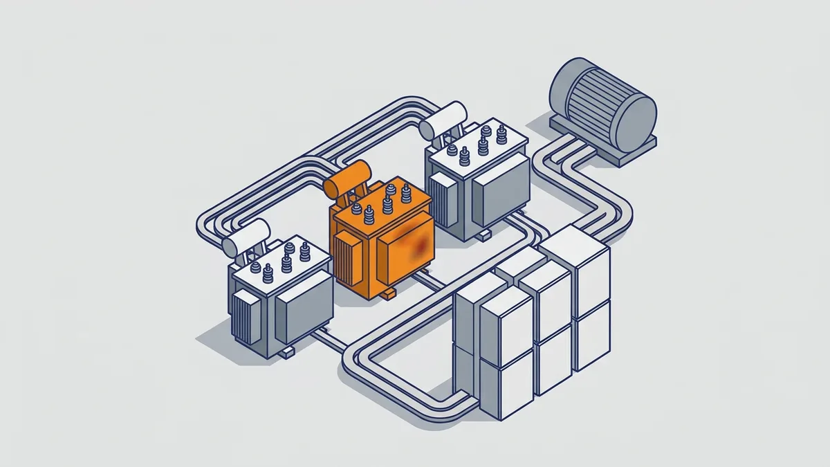
A 12 pulse VFD uses two 6-pulse rectifiers in parallel. A phase-shifting transformer feeds them two supplies that are 30 electrical degrees apart. Common designs use a transformer with a delta primary plus delta and wye secondaries, or an autotransformer or zig-zag winding.
Because of the 30-degree shift, the 5th and 7th harmonics from one bridge largely cancel those from the other. Then the 11th and 13th become the main harmonics. They also drop in size, but they do not go away.
Rockwell Automation’s Application Guidelines for 12-Pulse Operation (750-AT003) describes two setups:
- True 12-pulse: one drive with two input bridges.
- Quasi 12-pulse: two separate drives fed from one transformer, one on each secondary.
In both cases, the loads must stay balanced, or the cancellation falls apart. So with a 12-pulse VFD, what is it you actually buy? You buy a transformer and a second bridge that work as a team.
How much harmonic reduction does a 12-pulse drive give, and what are its limits?
Danfoss says its VLT 12-Pulse Drive reaches about 12% current distortion at full load under ideal grid conditions. It also lists true and displacement power factor above 0.98. Another source gives a typical 12-pulse figure of roughly 10%. In one test paper, 12-pulse measured 12% against 29% for 6-pulse at full load under the same conditions.
However, 12-pulse has real limits:
- Special transformer: higher cost, more space and special construction.
- Efficiency: the transformer’s voltage drop affects overall drive system efficiency.
- Imbalance and light load: both reduce cancellation. In that same paper, distortion rose as high as 65% at lower load with 3% voltage imbalance.
- Not a cure-all: it reduces harmonics but does not remove them, and the system may still fail an IEEE 519 target.
So where does 12-pulse make sense? Danfoss notes the transformer suits jobs that already need a step-down from medium voltage or isolation from the grid. In that case, the transformer does double duty. Also, ask any supplier for distortion figures at your expected load and imbalance, not just at full load.
What are the alternatives to a 12-pulse drive for meeting IEEE 519?
If 12-pulse is not the right fit for your VFD, what is it you can use instead? Several options exist, and each works differently. The distortion figures below come from the sources in this guide; for the rest, use the manufacturer’s data.
| Method | What it does | Typical current distortion |
|---|---|---|
| Plain 6-pulse, no mitigation | Baseline diode bridge | About 35% up to 80% |
| AC line reactor | Adds inductance to smooth the input current pulses | About 30 to 40% |
| DC choke | Smooths current on the DC bus inside the drive | Check manufacturer data |
| Passive filter | Tuned circuit that absorbs specific harmonic orders | Check manufacturer data |
| 12-pulse | Two bridges, 30 degrees apart, cancel the 5th and 7th | Roughly 10 to 12% at full load, balanced supply |
| 18-pulse | Three phase-shifted bridges cancel more low-order harmonics | Often specified near 5%; field results often 8 to 10% |
| Active filter | Injects opposing current to cancel harmonics | Check manufacturer data |
| Active front end | IGBT rectifier draws near-sine current and can regenerate | Check manufacturer data |
IEEE 519 sets harmonic limits at the point of common coupling (PCC), where your plant meets the utility. Its current limits use TDD (total demand distortion), not simple THD. In addition, the allowed level depends on the ratio of available short-circuit current to maximum demand current. So get the current edition of IEEE 519 for the actual limits, and ask an engineer for a harmonic study on large or drive-heavy sites.
Modbus and VFDs: controlling a drive over RS-485
Modbus is an industrial fieldbus, a protocol that lets controllers and devices share data. Modicon created it, and Schneider Electric bought Modicon in 1997. Today, the Modbus Organization specifications page carries the application protocol, version V1.1b3, which describes the function codes.
Modbus runs over serial lines as Modbus RTU on RS-485, over Ethernet as Modbus TCP, and over IP networks. Most drives offer Modbus RTU built in or on an option card. So for a Modbus VFD, what is it that changes? You swap hard-wired start, stop and speed signals for data on one cable.
The setup follows a master and server pattern. The PLC or HMI acts as the master, or client, and starts every exchange. Each drive acts as a server and answers only when asked. Because the master asks one drive at a time, drives never talk over each other.
How do I control a VFD with Modbus? Setup checklist
On each drive, set these items before you test from the PLC:
- Protocol: select Modbus RTU if the drive offers several.
- Address: give each drive a unique address from 1 to 247.
- Baud rate, parity and stop bits: match the master exactly.
- Command source: switch run and stop to the serial port.
- Speed reference source: switch it to the serial port too.
- Comm-loss timeout: set it so the drive stops or goes to a safe state if the PLC stops talking.
Parameter names and numbers vary by brand. Here are a few examples from published setup guides. Always confirm the values in your own drive’s manual.
| Drive | Example Modbus settings |
|---|---|
| Siemens SINAMICS G120C | p2030 = 2 selects Modbus RTU; p2021 sets the node address |
| Danfoss VLT FC 301/302 | Modbus setup in parameters 8-30 and 8-31 |
| ABB ACS/ACH550 | Parameter 9802 COMM PROTOCOL SEL = 1 (STD MODBUS) enables Modbus; group 53 holds the EFB settings |
| ABB ACS/ACH580 | Group 58 is the embedded fieldbus group (58.01 protocol, 58.03 node address) |
| Yaskawa GA500 | b1-01 and b1-02 set to 2 for Modbus speed and run commands; DIP switch S2 turns on termination |
How do I wire and terminate Modbus RS-485 for drives?
On a daisy-chained VFD network, what is it that keeps signals clean? Mostly good wiring practice. Follow these rules:
- Run a 2-wire daisy chain from drive to drive, not a star.
- Connect D+ to D+ and D- to D-. Some brands label these A and B, so check the manual.
- Fit 120 ohm termination at both ends of the segment, and nowhere else.
- Ground the cable shield at one point only.
- Connect the signal ground or common reference where the drive provides one.
- Keep the cable away from motor leads and other power wiring.
Also plan for network size. One RS-485 segment supports 32 standard loads, or more with low-load transceivers. In practice, time is the real limit, because the master polls one drive at a time. So more drives mean slower updates for each one.
Which Modbus registers and function codes does a VFD use?
Most drives support three function codes: 3 (read holding registers), 6 (write single register) and 16 (write multiple registers). The usual pattern is to write a control word and a speed reference, then read back the status word and actual speed. Many maps also list output current and DC bus voltage.
Scaling is vendor-specific. For example, some drives treat hex 4000 as 100% reference. Others use 0.01 Hz units, so 0x1770 (6000) means 60.00 Hz. One setup guide starts by writing 0x0001 to the control word, but that works only on drives with that control word layout.
Most important, register maps are not standard between brands. Siemens, Danfoss and ABB, for instance, use different control word and setpoint registers. So always use the Modbus chapter in your drive’s own manual. When the network drops a VFD, what is it usually? Look for these common mistakes:
- Address off by one, such as 40001 in the manual versus register 0 in the PLC.
- Parity or baud rate that does not match the master.
- Missing or doubled termination.
- Command source still set to keypad or terminals.
- No comm-loss timeout set.
How to wire and ground a VFD for EMC
A drive’s fast switching creates electrical noise, so good wiring matters as much as the drive itself. EMC means electromagnetic compatibility, which is the drive’s ability to run without upsetting nearby equipment. Follow the drive manual first, and use these common practices.
Shielded motor cable and 360-degree shield termination
Use shielded cable made for drives between the VFD and the motor. Symmetrical cable with three phase conductors and a ground conductor is a common choice. Then terminate the shield all the way around, a method called 360-degree termination, using metal clamps or EMC glands at the drive and at the motor. Avoid long pigtail wires for the shield, because they cut the shield’s value at high frequency.
EMC/RFI filter and ground-fault effects
Many drives have a built-in EMC or RFI filter. The filter uses capacitors to ground, and those capacitors raise ground leakage current. On an ungrounded or high-resistance grounded system, the manual often tells you to disconnect the filter with a jumper or screw. If you skip that step, ground fault trips and damaged parts can follow. For more on ground fault trips, see our post on VFD ground faults.
Separation distances
Keep motor cable away from control and signal wiring. Many manuals ask for about 12 inches (300 mm) or more between them. Also cross the two at 90 degrees when they must meet, and run motor leads in their own conduit or tray. The drive manual lists the exact distances for your model.
What do common VFD fault codes mean, and what do I check first?
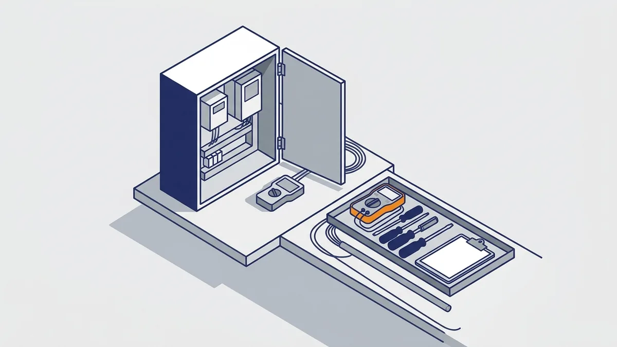
Fault code numbers and names change by brand, so look yours up in the manual. Still, most drives group faults into the same few types. The table gives the usual meaning and a first check for each.
| Fault | What it usually means | Check first |
|---|---|---|
| Overvoltage | DC bus voltage rose too high | Deceleration time, braking resistor, high line voltage |
| Undervoltage | DC bus voltage fell too low | Line sag, blown fuse, lost phase, loose input connections |
| Overcurrent | Output current went above the limit | Jammed load, acceleration time, motor data, output short |
| Ground fault | Current is leaking from the output to ground | Motor and cable insulation, wet or damaged cable |
| Overtemperature | Heatsink or internal temperature is too high | Fans, dirty filters, ambient temperature, overload, carrier frequency |
Before you reset any fault, write down the code and the operating state when it happened. Next, remove power, wait for the bus to discharge, and then inspect. For a ground fault, disconnect the motor leads from the drive and test the motor and cable with an insulation tester. Never apply that test voltage to the drive. Finally, if a fault returns after the basic checks, call for help. For heat problems, see our VFD overheating post.
Common VFD installation and application mistakes
Ask a repair tech about a failed VFD, what is it they see most often? Usually, the root cause traces back to setup, not the drive itself. Watch for these mistakes:
- Sizing by hp alone instead of motor current and load type. See our 3 Phase Motor VFD guide.
- Using the cube law on constant torque loads or systems with static head.
- Ignoring harmonics until a transformer or generator problem shows up.
- Poor grounding and long, unshielded motor leads. See our ground fault and short-circuit trip post, and use the drive and motor manufacturers’ limits for lead length and insulation.
- Heat and poor ventilation. See our VFD overheating post.
- Wiring errors. See our VFD wiring guides.
- Wrong command source or no comm timeout on networked drives.
Where to find VFD manuals, software and parts
Where do I find a VFD manual or Modbus register map? Go to the manufacturer’s manual library on its website and search for your exact model or type code from the nameplate. Most makers post their drive setup software on the same support site. Two manuals matter most:

- Programming manual: the parameter list and the Modbus register map.
- Installation manual: wiring, ratings and clearances.
ABB drive owners can read our post on ABB type codes and manuals. Use Rockwell Automation’s 750-AT003 guidelines and the Danfoss VLT 12-Pulse Drive page for 12-pulse design. The Modbus Organization specifications page covers the Modbus protocol itself. For energy savings, use DOE Motor Tip Sheet 11, DOE’s Variable Speed Pumping guide and Rockwell’s adjustable frequency drive energy paper.
Found an old, unlabeled VFD? What is it, and which manual fits? Precision Electric can help identify the drive from a nameplate photo. In addition, we distribute a full range of variable frequency drives through our webshop with free technical support and free shipping.
When to repair, replace or ask for help
Some symptoms call for a closer look or a repair. Watch for these signs:
- Repeated trips with no clear process cause.
- Failed bus capacitors or cooling fans.
- A failed power stage, such as a shorted rectifier or IGBT.
- A damaged display or control board.
Should I repair or replace a VFD?
For a failed VFD, what is it smarter to do, repair or replace? Repair often makes sense when the model is current and swapping it would mean rewiring and reprogramming. On the other hand, replacement makes more sense when the model is obsolete, parts are hard to get, or downtime matters more than reuse. Also replace when the job now needs more than the old drive offered, such as harmonic mitigation or a Modbus option card.
What are the repair-or-replace thresholds?
No standard sets a hard line, but these checks help you decide:
- Cost ratio: a common rule of thumb is to replace when the repair quote nears half the price of a new drive. Treat it as a guide, not a law.
- Lead times: compare the repair turnaround with the time to get a new drive. Ask both your repair shop and your supplier, because lead times change.
- Obsolescence: check the manufacturer’s lifecycle status for your model, such as active, limited or obsolete. An obsolete drive can leave you with few parts and no support.
- Stored spares: electrolytic capacitors age on the shelf. Many makers say to reform them if a drive has sat for a year or more, and the usual method applies power slowly or in steps. Follow your maker’s procedure.
- What a repair includes: ask for the scope in writing. A good repair usually covers testing, replacing failed power parts, capacitors or fans, cleaning and a final test.
What to have ready when you call
Precision Electric offers VFD repair nationwide and free technical support. For local customers in northern Indiana, we also provide integration services. Before you call, gather this information:
- Nameplate data from the drive and the motor.
- The exact fault code and when it appears.
- The application, such as fan, pump or conveyor.
- The control method: keypad, analog, terminals or Modbus.
Frequently asked questions
What is a VFD?
A VFD (variable frequency drive) is a power electronics device that controls the speed and torque of an AC motor by changing the frequency and voltage it supplies. It rectifies line AC to DC, smooths it on a DC bus, then uses PWM to invert it back to variable-frequency AC. If you searched “VFD what is it,” the short answer is a motor speed controller.
How much energy can a VFD save?
On centrifugal fans and pumps with no static head, power falls with the cube of speed. DOE’s example shows a 20 hp fan at half speed needing 1/8 of full-load power. For any fan or pump VFD, what is it worth in the end? It depends on how many hours the load runs below full speed, and systems with static head or constant-torque loads save much less.
What is a 12-pulse VFD?
It is a drive with two 6-pulse rectifiers fed from supplies phase-shifted 30 degrees by a special transformer. That shift cancels most of the 5th and 7th harmonics. Danfoss quotes about 12% current distortion at full load under ideal grid conditions. However, voltage imbalance and light load reduce the benefit.
Can a VFD be controlled over Modbus?
Yes, because most drives support Modbus RTU over RS-485. For a Modbus VFD, what is it you set first? Set the protocol, a unique address (1 to 247), baud rate and parity, then switch the run and speed sources to the serial port. Register numbers vary by manufacturer, so use the drive’s manual.
What are the main parts of a VFD?
Inside any VFD, what is it you will find? There are three power stages: a rectifier (usually a diode bridge), a DC bus with capacitors, and an IGBT inverter that uses PWM to build the output. In addition, a control board, keypad and I/O handle the commands and protection.
Now you can answer “VFD, what is it?” from the line terminals to the motor shaft. A drive saves the most on variable torque loads that spend real hours below full speed. For harmonics and network control, the right answer depends on your supply, your load and the drive’s own manual. If you need help choosing, programming or repairing a drive, contact Precision Electric for free technical support, a quote or a repair, or browse our full range of variable frequency drives.