








Frequency Variable Motor Control: How a VFD Works and Fails
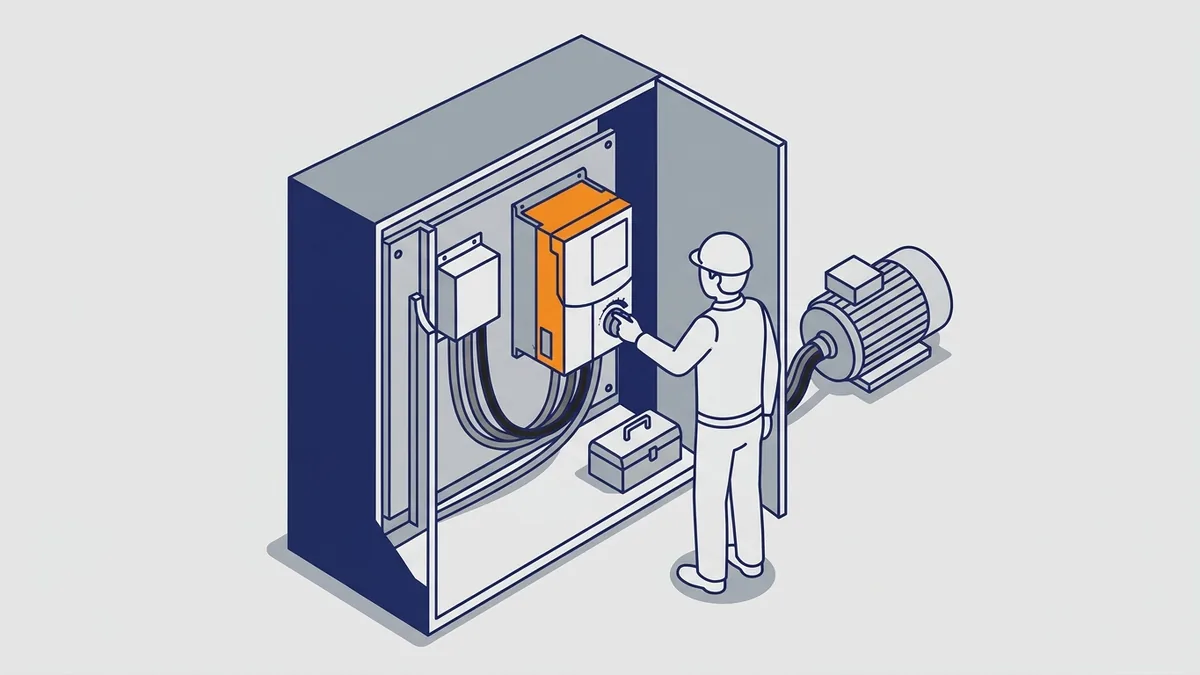
When you search for frequency variable motor control, you usually want to know how to change an AC motor’s speed with a drive. This guide explains what a variable frequency drive (VFD) is and how it works inside. You will also learn how to choose, install and troubleshoot one for a motor or pump, and when to repair it.
On this page
- What Is a Frequency Drive (Variable Frequency Drive)?
- Variable Frequency Drive Names Explained: VFD, AC Drive, Inverter and “Variable Frequency Driver”
- How a Variable Frequency Drive Works
- Why Use a VFD: Benefits and When You Don’t Need One
- Variable Frequency Pump Applications
- How to Choose and Size a Drive
- Is Your Motor Ready for a Drive? Insulation, Cable Length and Filters
- Power Quality: Harmonics, Line Reactors and DC Chokes
- Installing and Starting Up a VFD
- Troubleshooting Common VFD Faults
- Common VFD Mistakes
- Repair, Replace and Where to Get Manuals
- Frequently asked questions
What Is a Frequency Drive (Variable Frequency Drive)?
A frequency drive is a variable frequency drive, or VFD. It is a solid-state power electronics device, which means it switches power with semiconductors instead of moving parts. The drive controls the speed and torque of an AC induction motor. It does this by changing the frequency and voltage it supplies to the motor.
Without a drive, a motor runs on fixed 50 or 60 Hz line power, so it turns at one speed. A VFD sits between the line and the motor and replaces that fixed supply with an adjustable one. Because the drive makes the frequency variable, the motor speed becomes variable too. Inside, the drive turns incoming AC into DC, then builds new AC with a switching method called PWM.
This guide covers the whole path for one drive on one motor, from selection to repair. For a short definition, read our “VFD What Is It?” post first. For model-specific steps, see our ABB ACS model guides, our ACS355 lessons and our SMV setup post.
Variable Frequency Drive Names Explained: VFD, AC Drive, Inverter and “Variable Frequency Driver”
Buyers, techs and catalogs use many names for the same box. That mix of terms causes confusion when you order a part or search for a manual. So here is how the common names line up.
| Term | What it means |
|---|---|
| Variable frequency drive (VFD) | The standard name for the device |
| AC drive | The same device; common in catalogs and manuals |
| Variable speed drive | The same device, named for what it does to the motor |
| Inverter or inverter drive | The same device in daily use; strictly, the inverter is only the output stage |
| Variable frequency driver | A common misnomer for a VFD |
| Frequency variable drive, drive variable frequency, vfd variable frequency | Search phrases with the words reordered; all mean a VFD |
| Variable frequency pump | A pump run by a VFD |
Is a VFD the Same as an AC Drive or Inverter?
Yes, in everyday use. A VFD (variable frequency drive) controls an AC motor by changing frequency and voltage. An AC drive, a variable speed drive and an inverter drive all name that same device. Each one makes the frequency variable at the motor so you can set its speed.
Strictly speaking, though, “inverter” names only the output stage inside the drive. That stage turns DC back into AC. Still, many makers and techs call the whole unit an inverter, so you will see the word in manuals and part lists.
What Is a Variable Frequency Driver, and Is That the Right Term?
A variable frequency driver is the same thing as a variable frequency drive. However, “driver” is a common misnomer, and the correct trade term is “drive.” So if a quote request says frequency variable driver or variable frequency driver, treat it as a VFD. Also, writing “drive” on purchase orders avoids mix-ups with gate driver boards, which are parts inside the drive.
What Does “Drive Variable Frequency” Mean?
“Drive variable frequency” is a search phrase with the words in a different order. The same goes for “vfd variable frequency” and “frequency variable drive.” People type terms the way they come to mind. All of these point to a standard VFD.
You may also see “variable frequency pump.” That is simply a pump driven by a VFD, and it has its own section below. In short, any term that pairs a motor drive with a frequency variable output means the same family of equipment.
How a Variable Frequency Drive Works
So how does a VFD work? It takes fixed AC power and processes it in three stages. This path is what makes the frequency variable at the motor terminals.
- Convert: The rectifier turns incoming AC into DC.
- Smooth: The DC bus smooths that DC and stores energy.
- Rebuild: The inverter turns DC back into AC at the frequency and voltage you command.
Each stage also explains a common problem. For example, the rectifier causes harmonics, the DC bus causes overvoltage trips, and the inverter causes motor voltage spikes. As a result, knowing the stages makes troubleshooting much easier.
Rectifier, DC Bus and Inverter
First, the rectifier forms the input converter section. It uses a diode bridge to turn incoming AC into pulsating DC. A six-pulse bridge is the typical design on three-phase drives.
Next comes the DC bus, the middle section of the drive. Capacitors, and sometimes a choke, smooth the pulsating DC and store energy. On a 480 V drive, the peak rectified bus voltage is about 678 V. Typical bus voltage sits around 650 to 680 V DC, so treat the bus as live and dangerous.
Finally, the inverter section builds the output. It uses IGBTs, which are fast electronic switches, to turn the DC bus on and off. The rate of that switching is the carrier frequency, typically about 2 to 15 kHz.
What Is PWM and Why Does the Drive Use It?
PWM stands for pulse width modulation. The inverter switches the DC bus in fast pulses and changes the width of each pulse. As a result, the average voltage rises and falls in a sine-wave pattern at the frequency you command.
Because the motor windings smooth those pulses, the motor sees a near sine-wave current. That is the goal of PWM. In short, it lets a fixed DC bus create a frequency variable AC supply with very little wasted power.
Volts per Hertz and How Speed Is Commanded
How does a VFD change motor speed without losing torque? It lowers voltage together with frequency. This keeps the ratio of volts to hertz steady, so the motor’s magnetic field stays at the right strength. For example, a 460 V, 60 Hz motor run at 30 Hz gets roughly half its rated voltage. As a result, the motor can still produce its rated torque at the lower speed.
With the frequency variable and the voltage fixed, the motor would overheat at low speed. That is why the drive always moves both together.
Next, the drive needs a speed command, called the frequency reference. It can come from the keypad, a 4-20 mA signal, a 0-10 V signal, or a network command from a PLC. Then ramp times set how fast the frequency changes. Short ramps respond quickly but draw more current, while long ramps go easier on belts, gearboxes and pipes.
What Happens When the Load Pushes Back (Regeneration)
Some loads push back on the motor. For example, a lowering hoist or a heavy fan slowing down can turn the motor faster than the speed the drive commands. This is an overhauling load, and the motor now acts like a generator.
Why does my VFD trip on overvoltage when decelerating? The generated energy flows back through the inverter into the DC bus. However, the diode rectifier in a standard frequency variable drive blocks it from returning to the power line. So the energy has nowhere to go, and the bus voltage climbs until the drive trips to protect itself.
You have three main fixes. Choose based on how often and how hard the load brakes:
- Longer decel ramp: Slow the stop so the load gives up energy more gently.
- Braking resistor: A braking chopper sends excess bus energy to a resistor, which burns it off as heat.
- Regenerative unit: This returns the energy to the line, which suits large or frequent braking loads.
Also check the incoming line voltage. A high line raises the bus voltage before the motor even starts to slow.
How Do I Size a Braking Resistor or Choose a Regenerative Unit?
Start with the drive’s manual, because the maker sets the limits. First, the resistor’s ohms must not fall below the minimum the drive’s braking chopper allows. A lower value can overload the chopper. Next, the resistor’s power rating must handle the average braking power, not just the peak.
To estimate, find the peak braking power, which is about the motor power during the stop. Then multiply by the duty cycle, meaning the share of time the load is braking. For example, a load that brakes for 10% of each cycle needs a resistor rated for about 10% of the peak on average, plus the maker’s margin for short bursts. Also, the resistor must absorb the energy of one full stop.
Choose a regenerative unit when braking is large or frequent, or when wasting the energy as heat costs too much. Otherwise, a resistor is the simpler and cheaper choice. Ask the drive maker to confirm the final pick.
Why Use a VFD: Benefits and When You Don’t Need One
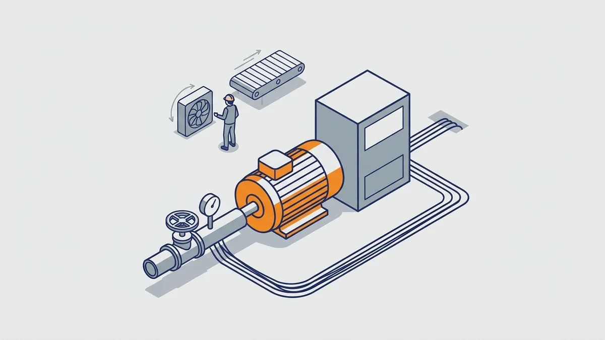
A frequency variable drive gives you control that a fixed-speed motor cannot. The main benefits include:
- Speed and torque control: You set the speed the process needs, not the speed the line gives you.
- Process control: The drive can follow a pressure, flow or level signal.
- Energy savings on variable loads: Fans and centrifugal pumps can use far less power at reduced speed.
- Controlled start and stop: Ramps cut mechanical shock on belts, couplings, gearboxes and pipes.
Why Use a VFD Instead of a Starter or Soft Starter?
Each option solves a different problem. An across-the-line starter connects the motor straight to full line voltage, so it runs at full speed only. A soft starter ramps the voltage to ease the start, but the motor still runs at full speed once it is up. By contrast, a VFD controls speed through the whole run.
| Feature | Across-the-line starter | Soft starter | VFD |
|---|---|---|---|
| Running speed | Fixed full speed | Fixed full speed | Adjustable |
| Starting | Full voltage, high inrush current | Reduced voltage, lower inrush | Low frequency with controlled current |
| Stopping | Coast | Coast or soft stop | Controlled ramp or braking |
| Energy savings on variable loads | None | None | Possible on fans and centrifugal pumps |
| Harmonics and motor stress | Lowest | Low | Higher; may need reactors, filters or an inverter-duty motor |
| Complexity | Lowest | Moderate | Highest |
In short, only the VFD keeps the frequency variable while the motor runs. That is the only way to match motor speed to demand.
When You Don’t Need a VFD
Savings are small on constant-torque loads and positive-displacement loads, because their power does not drop with the cube of speed. Savings are also small on systems that run near full speed all day. In those cases, making the frequency variable adds cost, heat and harmonics for little return. So if you only need a gentle start, a soft starter may be the simpler choice.
Variable Frequency Pump Applications
Pumps are the most common place a frequency variable drive pays off. A variable frequency pump runs slower when demand drops, instead of running flat out against a throttled valve. However, the savings depend on the pump type and the system, so check both before you promise results.
How Does a Variable Frequency Pump System Save Energy?
Centrifugal pumps follow the affinity laws. Flow changes with speed, head (pressure) changes with the square of speed, and power changes with the cube of speed. So doubling speed takes eight times the power. In the other direction, halving speed cuts ideal power use by about 87%, to roughly one-eighth.
| Pump speed | Flow | Head | Power (ideal) |
|---|---|---|---|
| 100% | 100% (full flow) | Full head | Baseline power |
| 75% | 75% | About 56% | About 42% |
| 50% | 50% | 25% | About 12.5% |
These figures are the ideal case for a centrifugal pump with no static head, so real systems save less. Still, the DOE’s guide “Variable Speed Pumping: A Guide to Successful Applications” reports savings of 30 to 50% in many rotodynamic (centrifugal-type) pump installations with variable speed drives. Treat that as an observed range, not a promise. Your load profile decides the actual result.
Do the Affinity Laws Work for Every Pump System?
No. Static head is the height or fixed pressure a pump must overcome before any liquid moves. The DOE guide calls it a common mistake to use the affinity laws to calculate savings in systems with static head. In those systems, flow no longer follows speed. Instead, a small turn-down in speed can sharply cut flow and pump efficiency.
For example, a pump that fills a high tank must always beat that lift. So a frequency variable pump on a high-lift system has a narrow useful speed range, and the savings shrink. Before you estimate savings, model the system curve or ask the pump maker.
Positive-displacement pumps are different again. Their energy use tends to track the volume pumped, and they present a constant-torque load. So the cube law does not apply, and the drive needs a constant-torque, heavy-duty rating.
Practical Setup for a Variable Frequency Pump
Most pump drives run in closed loop. The drive’s built-in PID controller, a loop that compares a setpoint with real feedback, adjusts speed to hold pressure or flow. In other words, the drive keeps the frequency variable so the process value stays steady. Set these items with care:
- Feedback: A pressure or flow transmitter, often 4-20 mA, wired to an analog input.
- Minimum speed: A floor that keeps the pump above the point where it stops making useful flow.
- Ramp times: Long enough to avoid water hammer and pressure swings.
- Sleep and wake: Stops the pump at low demand and restarts it when pressure drops.
Take the exact parameter numbers and values from the drive’s manual, since every maker labels them differently. For a model-specific example, see our ACS310 pump and fan post.
How to Choose and Size a Drive
How do I size a VFD for a motor? Start with the motor nameplate full-load amps (FLA), not horsepower or kW. The drive’s continuous output current must meet or exceed the motor’s FLA. Horsepower and kW only help you narrow a catalog. Because two motors with the same horsepower can draw different current, current is what matters to a frequency variable drive.
For example, a centrifugal pump on a 25 HP motor can often use a 25 HP drive, because the load is variable torque. However, a positive-displacement pump on the same motor may need a step up to a 30 HP drive. In both cases, confirm the choice against the motor’s actual FLA.
Load Type and Duty Rating: Normal Duty vs Heavy Duty
Normal duty or heavy duty: which rating do I need? It depends on the load. Many frequency variable drives carry two ratings, and the practical difference is overload current.
| Duty rating | Typical overload | Suits |
|---|---|---|
| Normal duty | About 110% for 60 s | Variable-torque loads: centrifugal pumps, fans, blowers |
| Heavy duty | About 150% for 60 s | Constant-torque loads: conveyors, compressors, extruders, mixers, positive-displacement pumps |
Here is the failure case. Suppose you put a normal-duty drive on a loaded conveyor. The conveyor needs high torque at low speed to break away, and the drive cannot supply enough overload current. As a result, it trips on start or stalls, again and again.
So match the duty rating to the load, not just the motor size. Also note that a drive’s heavy-duty current rating is usually lower than its normal-duty rating. Read the right column in the catalog.
Voltage, Phase, Enclosure and Derating
First, match the supply voltage and phase to the drive, and the drive output to the motor. For example, a 480 V motor needs a 480 V class drive. If your site only has single-phase power, confirm the drive is rated for single-phase input before you buy.
What derating applies to a VFD at high ambient, altitude or carrier frequency? Many drives need derating when the ambient is above 40 °C, the altitude is above 1,000 m, or you raise the carrier frequency. ABB manuals state that ratings apply at 40 °C, and ABB’s temperature derating is 1% per °C above that. Hot or thin air cools a frequency variable drive less, and faster switching makes more heat in the IGBTs. The amount differs by model, so use the drive’s published derating table. Then size the drive so its derated current still meets the motor FLA.
Finally, choose an enclosure for the environment. A NEMA Type 1 enclosure suits clean indoor areas. Dusty or dripping areas call for Type 12, while washdown or corrosive areas call for Type 4X.
Where Do I Find Derating Tables and Cable Length Limits?
The percentages differ by drive family and even by model, so do not use a general number. Look in the drive’s hardware or user manual, usually in the technical data or ratings section. For ABB drives, use the ABB Library. For Allen-Bradley drives, use the Rockwell Automation Literature Library. Yaskawa publishes its technical manuals the same way.
Look for tables that list current by ambient temperature, altitude and carrier frequency. Also look for the maximum motor cable length, which often depends on carrier frequency and whether you add an output filter. If you cannot find a table for your model, ask the maker or call us with the model number.
Can I Run a Single-Phase Supply Into a Three-Phase Drive?
Only if the drive maker allows it. Some drives are rated for single-phase input, and others are not. On a drive that allows it, the output to the motor is still three-phase.
The reason for caution is that single-phase input draws more current for the same power. It also makes the DC bus capacitors work harder. As a result, makers that permit it publish a derating or a larger drive size. Follow that table in the manual, and size the input fuses and wiring for the higher input current. If the manual does not approve single-phase input, do not try it.
Control Mode and Features to Confirm
Every frequency variable drive offers one or more control modes. Pick the one your load needs:
- V/Hz (volts per hertz): Simple and robust. It suits fans, pumps and several motors on one drive.
- Sensorless vector: Uses a motor model for better low-speed torque and tighter speed control, without an encoder.
- Closed-loop vector: Uses an encoder for feedback. It suits precise speed or torque control, including full torque near zero speed.
Also confirm the features before you order. Check the I/O count and type, the communications protocol, and whether the drive has a built-in DC choke or EMC filter. In addition, look for a braking chopper if you need a resistor. Finally, check for a Safe Torque Off (STO) input if your safety design calls for one.
For speed control and vector tuning on one model, see our ACS355 lessons. They walk through these modes on a real drive.
How Do I Size Input Fuses, Breakers and Conductors?
Use the drive manual first. It lists the input fuse or breaker type and size the drive was tested with. Using that exact type also keeps the drive’s short-circuit current rating (SCCR) valid. The SCCR is the highest fault current the drive can safely handle with the right protection ahead of it.
Next, check the SCCR against the available fault current where you install the drive. The SCCR must be equal to or higher than that fault current. If it is lower, you need current-limiting fuses or another approved fix from the maker.
For conductors, the NEC requires branch-circuit conductors to carry at least 125% of the drive’s rated input current. Size from the drive’s input current, not the motor’s. Then confirm the local code and the manual, since they may add rules.
Is Your Motor Ready for a Drive? Insulation, Cable Length and Filters
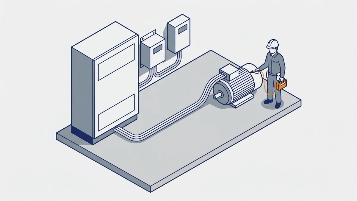
The drive’s fast switching is great for control, but it stresses the motor and cable. So before you connect a frequency variable supply to an existing motor, check its insulation and the cable run.
Can I Run Any Motor on a VFD?
Not always. Each PWM pulse has a very fast rising edge. When those edges travel down the motor cable, they can bounce back at the motor terminals, an effect called reflected wave. As a result, the voltage at the motor can climb toward twice the DC bus voltage.
Inverter-duty motors built to NEMA MG1 Part 31 are the baseline for drive use. However, sources state the Part 31 spike limit in two ways. Rockwell’s drives application technique (drive-at001) cites 1,600 V peak at a 0.1 µs rise time. Another source cites 3.1 times rated line-to-line voltage, about 1,426 V peak on a 460 V motor. So check the motor maker’s data for the actual rating.
Also think about cooling. A standard motor with a shaft-mounted fan moves less air at low speed. If you run it slowly under load for long periods, check with the motor maker first.
How Long Can the Cable Between the VFD and Motor Be?
There is no single answer for every drive. The safe length depends on motor insulation, cable type, voltage and carrier frequency. Instead of trusting a rule of thumb, check the drive and filter maker’s length tables.
On a frequency variable system, cable distance is a key factor in the voltage spike. In ABB Technical Note 176, peak voltage fell from 1,300 V to 1,020 V when ABB moved the motor to 50 ft from the drive. ABB also says a motor not rated to NEMA MG1 Part 31 may need a dV/dt filter at about 50 ft of cable or more. Meanwhile, Rockwell’s drive-at001 lists Part 31 motors and limited cable length as its main fixes.
Filters and Cable Options for Long Runs
When the run is long or the motor is older, you have several tools. Pick them using the maker’s tables for your drive and motor:
- dV/dt filter: Slows the pulse edges to cut the spike at the motor.
- Output reactor: Adds impedance on the drive output, which softens the edges on moderate runs.
- Sine filter: Smooths the output close to a sine wave, for the longest runs or sensitive motors.
- VFD-rated shielded cable: Controls noise and gives high-frequency current a clean path back to the drive.
Bearing Currents and Shaft Grounding
Drives can also induce voltage on the motor shaft. That voltage can discharge through the bearings and pit them over time. Shaft grounding rings and insulated bearings are common fixes. Because the right choice depends on the motor and system, follow the motor or drive maker’s guidance.
Power Quality: Harmonics, Line Reactors and DC Chokes
Every frequency variable drive with a diode rectifier draws current in short pulses, not a smooth sine wave. That current distorts voltage and current across your electrical system. These distortions are harmonics, which are extra currents at multiples of the line frequency. For example, a plain six-pulse drive with no added impedance typically shows input current THD (total harmonic distortion) of about 35 to 80%. Eaton cites about 80% without a reactor. With a 3% reactor or a DC choke, the figure drops to roughly 40%.
IEEE 519 sets harmonic limits, and those limits apply at the point of common coupling (PCC). The PCC is where your plant connects to the utility or to other users, not the drive terminals. So compliance depends on the whole system, including every frequency variable load on that supply. One drive in a large plant may matter little, while many drives on a small transformer may matter a lot.
Do I Need a Line Reactor or DC Choke on My VFD?
Often, yes. A DC choke sits between the rectifier and the DC bus, while an AC line reactor sits ahead of the drive on the incoming line. Both smooth the input current and reduce harmonics. They are also similar in cost and performance.
Eaton’s paper “AC Line Reactors vs. DC Link Chokes” found that a 5% DC link choke gave lower 5th and 7th harmonic distortion than a 3% AC line reactor. Before you specify a 5% external AC reactor, check whether the drive already has a 3 to 4% DC choke. Some drives include other harmonic features too. For more detail, read our Line Reactors for VFDs guide.
However, a reactor or choke alone does not guarantee IEEE 519 compliance. If a study shows you need more, the next steps include:
- Passive or active harmonic filters
- Multipulse drives
- Active front-end drives
- Phase-shifting transformers
Installing and Starting Up a VFD
How do I set up and start a VFD for the first time? Before you power up a frequency variable drive for the first time, work in order and never rush the safety steps. The sequence below fits most drives, but your manual sets the exact parameters.
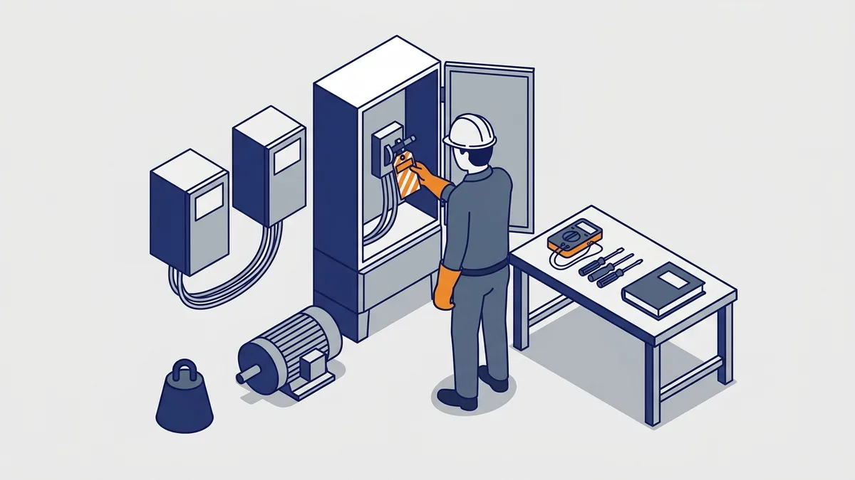
Step-by-Step First Startup
- Check the nameplates. Confirm the drive, motor and supply ratings all match.
- Measure the supply. Verify line voltage on all phases before you connect.
- Check wiring and grounding. Ground the drive and motor per the manual, and keep control wiring apart from power wiring.
- Work dead. De-energize, lock out, wait for the DC bus to discharge, and verify zero voltage before you touch terminals.
- Enter motor data. Key in nameplate voltage, full-load amps, base frequency and rated RPM.
- Set limits and control. Set minimum and maximum frequency, ramps, and the start and speed sources.
- Run with no load. Uncouple the motor if you can, check rotation, and watch current and speed.
- Run with load. Check current, temperature and response across the speed range.
- Record settings. Save or back up the parameters for the next tech.
How Do I Wire a Drive Correctly?
Start with the manual’s terminal layout and wiring diagram, since terminal names and positions differ by model. Wire the input power to the line terminals and the motor to the output terminals. Never swap them, because line power on the output terminals can destroy the drive.
Then keep power and control wiring apart. Run control and analog signal cables in separate conduit or trays from power cables. If they must cross, cross them at 90 degrees. Use shielded twisted pair for analog signals, and ground the shield at the drive end only unless the manual says otherwise.
For the motor cable, use VFD-rated shielded cable and ground the shield at both ends, with a full 360-degree connection. Also run a separate ground conductor from the motor back to the drive.
Finally, check the EMC filter. Built-in filters send leakage current to ground, which raises ground-leakage current. On ungrounded or corner-grounded supplies, the manual may tell you to disconnect the filter screw or jumper. Leakage can also trip ground-fault protection devices, so check that before startup.
Model-Specific Setup Guides
Many drives also offer an auto-tune step that measures the motor for vector control. Run it after you enter the nameplate data. For keypad steps on specific drives, see our “6 Step Basic Setup Of An SMV Variable Frequency Drive” post. Also see lessons 1 and 2 of our ACS355 series.
Troubleshooting Common VFD Faults
What causes common VFD faults and what do I check first? Most trips fall into a few groups. The table below lists the usual cause and a first check for each. For exact codes and meanings, use the fault list in your model’s manual.
| Fault type | Usual cause | First check |
|---|---|---|
| Overcurrent | Accel too fast, jammed load, short in motor or cable, wrong motor data | Ramp time, load, motor and cable condition, entered nameplate data |
| Overvoltage | Regeneration on fast decel or overhauling load; high line voltage | Decel ramp, braking resistor, incoming voltage |
| Undervoltage or phase loss | Low supply, blown fuse, loose connection, voltage sag | Voltage on all input phases, fuses, terminals |
| Overtemperature | Failed fan, clogged filters, high ambient, high carrier frequency | Fan, filters, heat sink, enclosure temperature, carrier setting |
| Motor overload | Motor current too high for too long; wrong FLA setting | Mechanical load, overload setting versus nameplate |
| Ground fault | Damaged motor or cable insulation, moisture | Insulation test of motor and cable, with the drive disconnected |
What Do Fault Codes Mean on ABB, Allen-Bradley and Yaskawa Drives?
Each maker uses its own codes, and codes can change between models in one brand. So always read the fault list in the manual for your exact drive. Yaskawa drives show short codes on the keypad, such as oC for overcurrent, ov for overvoltage, Uv1 for undervoltage, oH for heat sink overtemperature and GF for ground fault. ABB and Allen-Bradley use numbered codes with a name, so look up the number in the manual’s fault chapter.
To reset a fault, first find and fix the cause. Then clear it using the keypad reset key, a reset digital input, or a network command. If the manual allows, you can also cycle power, but wait for the DC bus to discharge first. Resetting without fixing the cause usually brings the same trip back, and repeated resets can damage the drive or motor.
Basic Checks Before You Replace Parts
Basic checks solve many problems. Work through these first:
- Measure input voltage on all phases.
- Check the output wiring and connections to the motor.
- Compare drive parameters with the motor nameplate.
- Clean the heat sink and confirm the fans and filters work.
- Note the age of the fans and DC bus capacitors, since both wear out.
Safety: Let the DC Bus Discharge
Every frequency variable drive stores energy in its bus capacitors. That charge can stay dangerous after you remove power. So wait the full time the manual states, then verify the bus voltage with a meter before you touch anything. Also, never insulation-test a motor with the drive still connected, because the test voltage can damage the drive.
How Long Should I Wait, and How Do I Verify the Bus Is Safe?
The wait time comes from the drive’s manual, so use that number. Many drives call for about five minutes, but larger drives and some models need longer. Do not guess, and do not rely on a dark keypad or a charge lamp alone.
Use this procedure:
- Open the supply disconnect, then lock out and tag out.
- Wait the full time in the manual.
- Use a voltmeter rated for the voltage and the work area, and test it on a known source first.
- Measure DC voltage across the DC bus terminals the manual names, and confirm it is near zero.
- Also check phase to phase and phase to ground at the input and output terminals.
- Test the meter again on the known source.
Follow your site’s electrical safety rules and the manual’s steps. If the bus does not drop, stop and call a qualified person.
Common VFD Mistakes
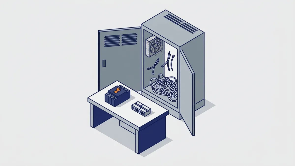
What mistakes do people make when applying a VFD? Most problems trace back to a few early choices. Avoid these, and your frequency variable system will run longer with fewer trips:
- Sizing by horsepower only: Size by motor FLA instead.
- Wrong duty rating: A normal-duty drive on a constant-torque load may not start it.
- Ignoring the motor: Skipping insulation and cable length checks risks motor failure.
- Misusing the cube law: Static-head systems save far less than the affinity laws suggest.
- Expecting the drive to fix harmonics: IEEE 519 compliance depends on the whole system at the PCC.
- Skipping nameplate entry: Without correct motor data, protection and control suffer.
- Running a standard motor slowly without checking cooling: Its fan moves less air at low speed.
- Overlooking derating: High ambient, altitude or carrier frequency all cut drive capacity.
Repair, Replace and Where to Get Manuals
When should a VFD be repaired or replaced, and where do I find manuals? The answer depends on the fault, the drive’s age and parts support. Here is how to decide.
When to Repair a Drive
Consider repair when the drive keeps tripping after you finish the basic checks. Repair also makes sense for power-stage faults, such as a failed IGBT or rectifier. In addition, repair is often the best path for an obsolete model that you cannot swap without rewiring or reprogramming.
When to Replace a Drive
Replace the drive when parts are no longer available. Replacement also fits when you want a retrofit to a modern drive with better control or communications. If you replace, size the new frequency variable drive by motor FLA and duty, not by the old drive’s horsepower.
How Do I Judge Drive Age, Capacitor Life and Parts Availability?
Start with the nameplate. The serial number or date code shows when the drive was built. Then check the maker’s product lifecycle status for your model, which usually reads active, limited or obsolete. An obsolete status means parts will get harder to find.
Next, think about wear parts. Electrolytic capacitors in the DC bus age faster with heat, and a common rule says each 10 °C drop in operating temperature roughly doubles their life. Cooling fans also wear out. A drive that has run hot for years is a stronger replacement candidate than one that ran cool.
For cost, we cannot give a typical price, because it depends on the drive size and the fault. Instead, get a repair quote and a replacement quote, and compare them on equal terms. Include the time to rewire and reprogram a new model, and the cost of downtime.
What to Have Ready When You Call
Gather a few details before you call for repair or a quote. They speed up diagnosis and help match a replacement:
- Drive model and serial number
- Motor nameplate data
- The fault code and when it occurs
- The application, such as pump, fan or conveyor
Where to Find Manuals and Software
Get manuals, fault lists and setup software from the drive maker’s online literature library. For example, use the ABB Library for ABB drives and the Rockwell Automation Literature Library for Allen-Bradley drives. For deeper topics, use the DOE’s Variable Speed Pumping guide, ABB Technical Note 176, Rockwell’s drive-at001 and Eaton’s AC Line Reactors vs. DC Link Chokes paper.
What Drives the Cost of a VFD?
Several factors set what a drive costs. Power rating matters most, since more current means a bigger drive. Also, the enclosure type, the duty rating, and options like filters, chokes, braking and communications all add cost. So define the load and environment first, then compare quotes on equal terms.
Frequently asked questions
What is a frequency drive?
A frequency drive is a variable frequency drive (VFD). It is a solid-state device that controls an AC motor’s speed and torque by changing the frequency and voltage it supplies. It converts incoming AC to DC, then builds a new frequency variable AC output with PWM.
How does a VFD control motor speed?
The inverter section switches the DC bus voltage on and off very fast, a method called PWM. This creates AC at the frequency you command, and motor speed follows that frequency. Also, the drive lowers voltage along with frequency so the motor keeps its torque.
Can a variable frequency drive save energy on a pump?
Yes, on centrifugal pumps. Ideal power varies with the cube of speed, and the DOE reports 30 to 50% savings in many rotodynamic pump installations. However, systems with high static head save less, and positive-displacement pumps do not follow the cube law.
How do I size a VFD for my motor?
Use the motor nameplate full-load amps, not horsepower. The drive’s continuous output current must meet or exceed FLA. Then choose the duty rating for the load: about 110% overload for centrifugal pumps and fans, and about 150% for constant-torque loads such as conveyors.
Do I need an inverter-duty motor with a VFD?
Inverter-duty motors built to NEMA MG1 Part 31 handle the voltage spikes a drive produces, so they are the baseline for long cable runs. For motors not rated to Part 31, ABB says you may need a dV/dt filter at about 50 ft of cable or more. So check the motor maker’s data before you connect an older motor.
A VFD makes the frequency variable so your motor runs at the speed the process needs. Size it by FLA and duty, protect the motor and power system, and start it up with care. Then most frequency variable problems become simple checks instead of long outages.
If you need help choosing, sizing or repairing a drive, contact Precision Electric for a quote or repair, or browse our VFD products.