Inverter Repair

Most inverterrepair can be prevented with routine maintenance. Inverter repair costs and lead times can also be reduced with routine maintenance. Inverterrepair can be expensive and also cost manufacturers production downtime while the inverter repair is in process.Most manufacturers stock spare inverter modulesto prevent production downtime in the event of an inverter failure.Components used forinverter modules are often cheaply made and prone to failure. Knowledgeable inverter repair shops should replace cheaply made components with high quality components during the inverter repair process. Using high quality components in an inverter repair ensures a higher chance of success and a longer lifespan during production.

Connections
Checkingconnections is a step many people miss or do incorrectly during the inverterrepair process. Heat cycles and mechanical vibration can lead to sub-standard connections, as can standard preventative maintenancepractices. Reusing torque screws is not a good Idea, and further tightening an already tight connection can ruin the connection.Bad connections eventually lead to arcing. Arcing at the inverterinput could result in nuisance over voltage faults, clearing of input fuses, or damage to protective components. Arcing at the inverteroutput could result in over-current faults or even damage to the power components.

Loose connections can cause erratic operation. Loose START/STOP signal wires can cause uncontrollable inverterstarting and stopping. A loose speed reference wire can cause the drive speed to fluctuate, resulting in scrap, machine damage, or personnel injury.

Conduct Diode and IGBT Tests
There are a number of methods to test the input and output power sections of an inverter, and this step is essential prior to applying power to the inverterunit. If for any reason there is a short on the input side or output side of the inverter, further damage can be caused to the unit if power is applied to it.

For this reason, Precision Electric uses meters to properly test the input and output power sections of the inverter prior to applying power to the actual unit. If a short is found, the unit can be disassembled and the cause of the short can be diagnosed and quoted for repair. If the repair is too costly, then a replacement is offeredto the customer.

Power Up Unit
If the input and output power sections test healthy during this step of the inverter repair process, Precision Electric will power the unit and perform amp reading and output frequency tests. Precision Electric prefers to slowly increase power voltage to the unit until the rated input voltage of the inverter is achieved.

Depending on whether or not the inverter provides a display will determine what further action(s) will be taken. If display is unavailable, dis-assembly and diagnosis of the internal power supply of the control section of the inverter is likely necessary to further evaluate cause of failure and establish costand lead time for the inverter repair.

Run A Motor
If the previous three tests have passed during the inverter repair process, then it is time to run a basic jog function of the inverter with a simple template program. Often when an inverter comes into our facility, we make sure to backup whatever program is currently stored in the inverterprior to inputting a template program and running a test procedure. This ensure we have a backup copy of the program.

The best method for backing up depends on the brand of drive, but after it has been backed up, we either reset the inverterto factory defaults through the keypad and recommission a basic start, stop and job application or closed loop if an encoder is involved. If the motor will not run, it will be necessary to checkthe output voltages and current ratings going to the motor to see if the inverteris functioning properly to rotate the motor.

Contact Customer
At this point we have determined the cause of failure, estimated lead time and costof the inverterrepair. If the inverter has tested good entirely, then further underlying issues are communicated with the customer. This is when Precision Electricwill gather application specific information from the customer to establish whether or not it may be some outside issue associated with the system including, but not limited to, PLC communications, faulty IO, bad wiring or even bad cabling. There is no single way to do this step, as it really depends on a wide variety of variables.

Send Service Tech
If the customer cannot establish failure on any other aspect of the machine and the inverterappears to test fine, then it may be necessary to send a field service technician on site to establish cause of failure. Field service technicians should betrained to troubleshoot any issue ranging from standard inverterrepair, to advanced robotics, PLCs and more. Field technicians should also be trained to establish cause of failure and come up with solutions as quick as possible.

Inverter repair should be taken with extreme caution. Inverterrepair should only be performed by technicians who have required training and experience to work with electrical equipment. Precision Electric strongly recommends to consult an expert in the field when repairing or installinginverterequipment.Many invertercontrollers have an internal DC bus that retains a charge after power has been cut to the drive, as a result, it does not mean it’s safe to work with. Technicians working with inverter repair must always take extra precautions to ensure proper safety measures are taken, or injury or even death may occur.

For inverterrepair and inverter replacement quotes, contact Precision Electric.

ABB Motor Control Applications

ABBmotor control applications can be seen in every industry and in all power ranges. ABB motor control applications are compatible with virtually all processes, automation systems, users, and businessrequirements. The innovation behind ABB motor control applications isanarchitecture that simplifies operation, optimizes energy efficiency and helps maximize process output. ABB motor control applications in this article consist of ABB ACS880 single drives, ABB multi-drives and ABB drive modules.

ACS880 Multi-Drives

ABBACS880 multi-drives simplify industrial processes without limiting possibilities. ABB motor control applications using the ACS880 multi-drives can be built-to-order to meet customer needs and technical challenges through a wide selection of options; options that are all mountable within the drive cabinet. A single supply and DC bus arrangement with multipleACS880 multi-drives reduce line power, cabinet size and total investment costs. The features and options include extended I/O, field bus options, EMC filtering, brake options, fuses and main switch. Several ingress protection (IP) classes with IP22 and IP42 offering solutions for different environments are also available for ABB ACS880 multi-drives. ABB ACS880 multi-drives support induction motors, synchronous motors and induction servo motors as standard, without any additional software. ABB ACS880 multi-drives can control motors in either open loop or closed loop, through its high precision motor control platform, Direct Torque Control (DTC).

ACS880 Drive Modules

ABBACS880 drive modules are designed to be built into a control cabinet by machine builders and system integrators. With inverter power up to 3200 kW, ABB drivemodules are used to build multi-drive and high power single drive configurations. Everything that is required for a complete drive including rectifiers, inverters, brake options, EMC filters, du/dt filters, I/O options, communication options and documentation is available. ABB motor control applications using the ABB ACS880 drivemodules is versatile; and are used in industries such as metals, oil and gas, mining, marine, offshore, material handling machines, pulp and paper, automotive, food and beverage, cement, power, water and wastewater.

ACS880 Single Drives

ABBACS880single drives are compatible with a wide range of motor control applications in a broad range of industries such as oil and gas, mining, metals, chemicals, cement, power plants, material handling, pulp and paper, sawmills and marine. At the heart of the drive is Direct Torque Control (DTC), ABBs premier motor control technology. The extensive range of options include EMC filters, encoders, resolvers and brake resistors, remote monitoring tool, as well as application-specific software. Built in safety features reduce the need for external safety components. CODESYS programming capability is embedded inside the drive for making the application run more efficiently, without a separate programmable controller. Multiple drives can be daisy-chained for synchronized drive-to-drive communication. The drive offering includes two enclosure ratings, UL Type 1 (IP21) and UL Type 12 (IP55), for dusty environments. ABB ACS880 single drives also offer built-in service features.

Summary

ABB motor control applications can run in either open loop or closed loop, through their high precision motor control platform, Direct Torque Control (DTC).ACS880 motor control applications also have built-in safety features to reduce the need for external safety components. ABB motor control applications using the ACS880 support the CODESYS programming environment according to IEC 61131-3.ABB motor control applications have a common architecture that features the same control panel, parameter menu structure, universal accessories and engineering tools. The new control panel is equipped with an intuitive and high-resolution control display that enables easy navigation.ABB motor control applications using the energy optimizer control mode ensures maximum torque per ampere, reducing energy drawn from the supply.

To learn more about ABB motor control applications, visit theABB Website. Call Precision Electric for ABB repair or ABB replacement quotes.

Inverter Drives

Inverterdrives are also known as variable frequency drives, VFD’s, variable speed drives, adjustable frequency drives, AFD’s, adjustable speed drives and ASD’s. Inverterdrives are solid state motor control systems used to regulatethe speed of alternating (AC) electric motors. Inverter drives are mainly used to reduce energy consumption on electric motors for industrial manufacturers.

Inverterdrives operate as load controls within applications that may accomplish up to 50% reduction in energy costsby speed reduction on applications where the full speed (RPM) of the electric motor is not required. Inverterdrives are used in AC Servo Systems, Air Compressors, Conveyor Systems, Lathes, Mills, Plastic Extrusion, Slitter Lines, Food Processing, Waste Water Treatment Systems, Submersible Pumps, HVAC Fans and Blowers, and many more AC motor applications.

Many manufacturers apply inverterdrives withrotating equipment toreduce amperage spikes upon start up of large electric motors.Choosing the right inverterdrive for an application will benefit rotating equipment by providing less wear on the electric motors where applied; by adjusting the acceleration and deceleration time of electric motors, an electric motor’s lifespan is extended significantly. Inverter drives provide the ability to control the frequency of starting and stopping of an AC electric motor.This ability provides a means by which an AC electric motor is only operating when needed for the equipment it’s rotating, and electric motors have a longer lifespan if they are not continuously operating when they don’t need to be.

Approximately one third of the world’s electrical energy is supplied by electric motors in fixed-speed centrifugal pump, fan, and air compressor applications. These fixed-speed applications hardly ever require the full load speed (RPM) of the electric motor they’re operating. By installing inverter drives to these applications, the motor speeds are reduced, and power costs can be reduced by 50% or more. Technology has reduced cost and physical size of inverterdrives, and has improved performance through advances in semiconductor switching devices, simulation, control techniques, and control hardware and software.

Power Savings With Inverter Drives

The majority of inverter drives in the market today contain electronic circuitry that converts 60 Hertz Line power into direct current. The inverterdrive converts this line power into a pulsed output voltage that duplicates varying alternating current to a desired frequency (speed).A properly applied inverterdrive when paired with an AC electric motor, will significantly reduce operating costs. This is particularly true for variable torque loads such asFans,Blowers, andPumps.Blowers, for example, are often used with dampers to control air flow. These dampers may operate either manually or automatically. When dampers are closed, 50% of the electric motor current will drop to approximately 60% of Full Load nameplate current. By utilizing an AC variable frequency drive in this application, current draw in the motor will be reduced 30% for every 10% drop in speed. The same electric motor operating froman inverterdrive at 50% speed, will draw approximately 20% of the full load current.

Types Of Inverter Drives

Volts Per Hertz inverter drives are the most common type of drive and areknown as a V/Hz drives, or volts by hertz drives. V/Hz inverterdrives are used inapplications such as fans, pumps, air compressors, and other related applications wherehigh starting torque is not required. V/Hz drive applications typically do not require full torque when the AC motor is operating at less than the base speed (RPM) of the electric motor. V/Hz drives are the most inexpensive type of variable frequencydrive. V/Hz drives do not provide full motor torque at low RPM.

Open-Loop vector inverter drives are also known as “sensorless vector” drives. Open loop vector drives adapted the name “sensorless vector” because they do not use an external encoder for speed feedback to the motor.Open loop vector drives are used in applications where high starting torque and full torque at low speed (RPM) is required. Open-Loop vector drives operating a motor a zero RPM should not be used on crane or hoist applications. Most open-loop vector drives are used on CNC machines, mixers, mills, lathes, and other applications where high starting torque or full torque at low RPM is needed.Open loop vector drives are usually more expensive than V/Hz inverterdrives.

Closed-Loop vector drives are used in applications where precise speed control (0.01%) is needed, or in applications where extensive programming is needed. Closed-Loop vector drives use an encoder on the motor to provide constant shaft position indication to the drive’s microprocessor. The encoder feedback allows the drive microprocessor to constantly control torque no matter how many RPM the motor is operating at. Closed-Loop vector drives are used to provide the motor to operate at full torque even at zero RPM. Closed-Loop vector drives are commonly used on hoist and crane applications because crane and hoist motors must produce full torque prior to it’s brake being released, or the load will drop and it will not be able to stop.

To learn more about inverterdrives or for inverter drive repair and replacement quotes, contact Precision Electric, Inc.

ABB ACS355 Emergency Stop

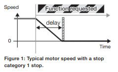
fig1+estopABB ACS355 emergency stop is usedfor applications that require risk reduction from unexpected and hazardous movement. The aim to integrate drive-based safety functions is to createmachines that are safe to use. This safety function example is presented to install ABB ACS355 emergency stop but these same functions can be implemented with other ABB drives with few modifications. ACS355 machinery drives offer a safe torque off (STO) safety function as a standard integrated feature. STO eliminates the need to use contactors, which means that the drive is not disconnected from the power during safe stopping. This again enables fast restart of the drive and the machine. STO is also offered as standard in many ABB drive types for easy integration of functional safety.

Overview of the Safety Function

ABB ACS355 emergency stop, stop category 1 (Figure 1), stops the drive with a controlled deceleration ramp before disabling the drives output to the motor. In this example, the deceleration ramp is time monitored. The safety function can be used in an application where a synchronized stop of multiple axes is required.

Design of the Safety Function

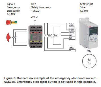
fig2+estopThe design of theABB ACS355emergency stop consists of an emergency stop button as an activating switch, a safety timer relay as a logic unit and a safe torque off (STO) -circuit inside the ACS355 drive. The drive acts as an actuator to bring the motor into a nontorque state after the deceleration. See circuit diagram (Figure 2) for connection details.

Operation of the safety function When the emergency stop button is pressed, the safety relay detects the button signal and opens its non-delayed contacts to inform the drive todecelerate. Simultaneously, the relays timer for the time delay contacts starts counting. After the time delay has elapsed, the contacts open, activating the STO function, which disables the drives power output to the motor. To continue drive operation after an emergency stop, the emergency stop button is released (pulled up), which causes the contacts of the relay to close. This deactivates the STO function. The drive is restarted by a separate start command. The drive is configured not to start automatically.

The safety relay is used to provide diagnostics for the emergency stop button wiring. The relay also enables the use of a separate reset button, if required (reset button is not shown in this example since it is not required by the standard). Ensuring the required safety performance The safety function has to fulfil the required safety performance determined by a risk assessment. ABBs Functional safety design tool (FSDT-01) is used to design the desired safety function.

This is carried out according to the Following Steps:

1. Evaluate the risks to establish target safety performance (SIL/PL level) for the safety function.

2. Design the safety function loop and verify the achieved performance (PL) or safety integrity level (SIL) for the safety function loop (according to EN ISO 13849-1 or EN/IEC 62061, respectively), utilizing the device safety data and the application specific characteristics.

3. Generate a report for the machine documentation. Report should contain all the calculation results as well as all assumptions made during the application design.

Safety function verification and validation In addition to the safety calculations for the achieved safety performance (SIL/PL), the safety function needs to be functionally verified as well. Finally the implemented safety function is validated against the risk assessment to ensure that the implemented safety function actually reduces the targeted risk.

General considerations Achieving machinery safety requires a systematic approach beyond the physical implementation of a safety function. The overall machinery safety generally covers the following areas:

  • Planning for and managing functional safety during the life cycle of the machine
  • Assuring compliance to local laws and requirements (such as the Machinery directive/CE marking)
  • Assessing machine risks (analysis and evaluation)
  • Planning the risk reduction and establishing safety requirements
  • Designing the safety functions
  • Implementing and verifying the safety functions
  • Validating the safety functions
  • Documenting the implemented functions and results of risk assessment, verification and validation

For more information concerning the ABBACS355 emergency stop function, visit the ABB Website.For ABB drive repair quotes or ABB drive replacement quotes, contact Precision Electric.


ABB DTC

ABB DTC or Direct Torque Control, is the most advanced AC drive technology developed by any drive manufacturer in the world.With the revolutionary ABB DTC technology, field orientation is achieved without feedback using advanced motor theory to calculate the motor torque directly and without using modulation. The controlling variables are motor magnetising flux and motor torque. With ABB DTC, there is no modulator and no requirement for a tachometer or position encoder to feed back the speed or position of the motor shaft. ABB DTC uses the fastest digital signal processing hardware available and a more advanced mathematical understanding of how a motor works. The result is a drive with a torque response that is typically 10 times faster than any AC or DC drive. The dynamic speed accuracy of ABB DTC drives will be 8 times better than any open loop AC drives and comparable to a DC drive that is using feedback. ABB DTC produces the first universal drive with the capability to perform like either an AC or DC drive.

There are many benefits of ABB DTC technology. But most significantly, drives using ABB DTC technology have the following exceptional dynamic performance features, many of which are obtained without the need for an encoder or tachometer to monitor shaft position or speed: Torque response: How quickly the drive output can reach the specified value when a nominal 100 percent torque reference step is applied. For DTC, a typical torque response is 1 to 2 ms below 40 Hz compared to between 10-20 ms for both flux vector and DC drives fitted with an encoder. With open loop PWM drives,the response time is typically well over 100 ms. With its torque response, ABB DTC has achieved the natural limit. With the voltage and current available, response time cannot be any shorter. Even in the newer sensorless drives the torque response is hundreds of milliseconds. Accurate torque control at low frequencies, as well as full load torque at zero speed without the need for a feedback device such as an encoder or tachometer. With ABB DTC, speed can be controlled to frequencies below 0.5 Hz and still provide 100 percent torque right the way through to zero speed. Torque repeatability:How well the drive repeats its output torque with the same torque reference command. ABB DTC, without an encoder, can provide 1 to 2 percent torque repeatability of the nominal torque across the speed range. This is half that of other open-loop AC drives and equal to that of closed-loop AC and DC drives.

Motor static speed accuracy:Error between speed reference and actual value at constant load. For ABB DTC, speed accuracy is 10 percent of the motor slip, which with an 11 kW motor, equals 0.3 percent static speed accuracy. With a 110 kW motor, speed accuracy is 0.1 percent without encoder (open-loop). This satisfies the accuracy requirement or 95 percent of industrial drives applications. For the same accuracy from DC drives an encoder is needed. In contrast, with frequency controlled PWM drives, the static speed accuracy is typically between 1 to 3 percent. So the potential for customer process improvements is significantly higher with standard drives using ABB DTC technology. An ABB DTC drive using an encoder with 1024 pulses/revolution can achieve a speed accuracy of 0.01 percent. Dynamic speed accuracy:Time integral of speed deviation when a nominal (100 percent) torque speed is applied. ABB DTC open-loop dynamic speed accuracy is between 0.3 to 0.4%sec. This depends on the gain adjustment of the controller, which can be tuned to the process requirements. With other open-loop AC drives, the dynamic accuracy is eight times less and in practical terms around 3%sec.If we furnish the ABB DTC controller with an encoder, the dynamic speed accuracy will be 0.1%sec, which matches servo drive performance.

Standard applications account for 70 percent of all variable speed drives installed throughout industry. Two of the most common applications are in fans and pumps in industries like heating, ventilating and air conditioning (HVAC), water and food and drinks. In these applications, ABB DTC provides solutions to problems like harmonics and noise. For example, ABB DTC technology can provide control to the drive input line generating unit, where a conventional diode bridge is replaced with a controlled bridge. This means that harmonics can be significantly reduced with a DTC controlled input bridge. The low level current distortion with an ABB DTC controlled bridge will be less than a conventional 6-pulse or 12-pulse configuration and power factor can be as high as 0.99. For standard applications, ABB DTC drives easily withstand huge and sudden load torques caused by rapid changes in the process, without any overvoltage or overcurrent trip. Also, if there is a loss of input power for a short time, the drive must remain energised. The DC link voltage must not drop below the lowest control level of 80 percent. To ensure this, DTC has a 25 microseconds control cycle.

There are vast differences between ABB DTC and many of the sensorless drives. But the main difference is that ABB DTC provides accurate control even at low speeds and down to zero speed without encoder feedback. At low frequencies the nominal torque step can be increased in less than 1ms. This is the best available, because the motor is now the limit of performance and not the drive itself. A typical dynamic speed accuracy for a servo drive is 0.1%s. An ABB DTC drive can reach this dynamic accuracy with the optional speed feedback from a tachometer. The most striking difference is the sheer speed by which ABB DTC operates. As mentioned above, the torque response is the quickest available. To achieve a fast torque loop, ABB has utilised the latest high speed signal processing technology and spent 100 man years developing the highly advanced motor model which precisely simulates the actual motor parameters within the controller.

To learn more about ABB DTC or for ABB drive repair and replacement quotes, contact Precision Electric.

ABB Industrial Drives

ABB industrial drives are designed to tackle any motor-driven applications, in any industries, whatever the power range. ABB industrial drives are compatible with virtually all processes, automation systems, users and business requirements. The innovation behind ACS880 ABB industrial drives is architecture that simplifies operation, optimizes energy efficiency and helps maximize process output. The ACS880 ABB industrial drives consist of single drives, multidrives and drive modules.

ACS880 Multidrives

ABB ACS880 multidrives simplify industrial processes without limiting possibilities. ACS880 multidrives and ABB industrial drives can be built-to-order to meet customer needs and to meet technical challenges through a wide selection of options that are all mountable within the drive cabinet. A single supply and DC bus arrangement with multipleACS880 multidrives reduce line power, cabinet size and total investment costs. The features and options include extended I/O, fieldbus options, EMC filtering, brake options, fuses and main switch. The new cabinet design is more compact, including efficient thermal handling.Several ingress protection (IP) classes with IP22 and IP42 offering solutions for different environments are also available for ABB ACS880 multidrives. Induction motors, synchronous motors and induction servo motors are all supported as standard, without any additional software. ABB ACS880 multidrives can control motors in either open loop or closed loop, through its high precision motor control platform, direct torque control (DTC).

ACS880 Drive Modules

ABB ACS880 drive modules are designed to be built into a control cabinet by machine builders and system integrators. With inverter power up to 3200 kW, ABB drivemodules are used to build multidrive and high power single drives configurations. Everything that is required for a complete drive including rectifiers, inverters, brake options, EMC filters, du/ dt filters, I/O options, communication options and documentation is available. ABB ACS880 drivemodules are used in industries such as metals, oil and gas, mining, marine, offshore, material handling machines, pulp and paper, automotive, food and beverage, cement, power, water and wastewater.

ACS880 Single Drives

ABB ACS880-01 single drives simplify your world without limiting your possibilities. The ABB ACS880-01 is a wall-mounted single drive compatible with a wide range of applications in a broad range of industries such as oil and gas, mining, metals, chemicals, cement, power plants, material handling, pulp and paper, sawmills and marine. At the heart of the drive is direct torque control (DTC), ABBs premier motor control technology. The extensive range of options include EMC filters, encoders, resolvers and brake resistors, remote monitoring tool, as well as application-specific software. Built in safety features reduce the need for external safety components. CODESYS programming capability is embedded inside the drive for making the application run more efficiently, without a separate programmable controller. Multiple drives can be daisy-chained for synchronized drive-to-drive communication. The drive offering includes two enclosure ratings, UL Type 1 (IP21) and UL Type 12 (IP55), for dusty environments. ABB ACS880 single drives also offer built-in service features.

Conclusion

ACS880 ABB industrial drives can control motors in either open loop or closed loop, through their high precision motor control platform, direct torque control (DTC). ACS880 ABB industrial drives also have built-in safety features to reduce the need for external safety components. ACS880 ABB industrial drives support the CODESYS programming environment according to IEC 61131-3. ACS880 ABB industrial drives common architecture features the same control panel, parameter menu structure, universal accessories and engineering tools. The new control panel is equipped with an intuitive and high-resolution control display that enables easy navigation.

Many flexible data visualizations including bar charts, histograms and trend graphs help users to analyze processes, with assistants available to simplify setup. The menus and messages are customizable for the specific terminology of different applications. An integrated USB port allows easy connection to the Drive composer PC tool, which offers fast startup, commissioning and monitoring. The built-in energy calculators, including used and saved kWh, CO2 reduction and money saved, help the user fine tune processes to ensure optimal energy use. The energy optimizer control mode ensures the maximum torque per ampere, reducing energy drawn from the supply.

To learn more about ABB Industrial Drives, visit the ABB Website. For ABB industrial drives repair and replacement quotes, contact Precision Electric.
VFD Drives

VFD drives are known as Variable Frequency Drives. VFD drives are also known as variable speed drives (VSDs), adjustable speed drives, motor speed controllers and inverters. VFD drivesare solid state controllers used in AC or DC electric motor applications. Most VFD drives are applied on alternating current (AC) electric motors in the industrial manufacturing world. There are some direct current (DC) electric motor applications that apply variable frequency drives, but most manufacturers seek AC motors because DC motors are expensive and they’re more prone to failure. VFD drives can also be used as a phase converters when three phase motors need to be operated from single phase power.

VFDdrives areused in mills, lathes, fans, air compressors, pumps, conveyors, welders, robots and many other electric motor applications to control the speed regulation of an electric motor. Over 30 percent of the world’s electrical energy is consumed by electric motors in fixed-speed fan, pump, and air compressor applications. The basic idea for using a VFD on mills, air compressors, and fans is to decreasethe amount of electrical energy being consumed toreduce electricity costs.

Energy Savings

Only about3% of the total installed AC electric motors in the United States use VFDdrives.An estimated 60-65% of electrical energy in the United States is used to supply electric motors, and 75% of that electrical energy is consumed by fan, pump and air compressor applications.Approximately 18% of the electrical energy used in the 40 million motors in the United States could save power consumption via efficient energy improvement by using VFD drives on these electric motor applications.

Performance and Operation

VFDdrives are applied to alternating current (AC) electric motors to increase quality control and reduce energy consumption during the process of manufacturing.VFD drives increase quality control by monitoring the electric motor speed, pressure, temperature, torque, and tension; and then adjusting the motor to operate as economical as possible to meet the VFDcriteria.

Fixed-speed electric motor loads exposethe electric motor to high starting torque and electrical current surges that are up to eight times the full-load motor current. When VFDdrives are used on an electric motor, the VFDgradually ramps the electric motor up to full load operating speed; this decreases mechanical and electrical stress, which minimizes motor maintenance and motor repair costs which extends the life of the electric motor and manufacturing equipment.VFD drives haveunique programming capabilities that allow for application specific patterns to minimize electrical and mechanical stress on electric motors during operation. Every VFD drive manufacturer uses a unique parameter selection designed so that every manufacturing field has VFD products designed for their industry.

Repair and Replacement

VFD repair should be taken with extreme caution. VFD repair should only be performed by technicians who have required training and experience to work with electrical equipment. Precision Electric strongly recommends to consult an expert in the field when repairing VFD equipment.Many VFD controllers have an internal DC bus that retains a charge after power has been cut to the drive, as a result, it does not mean it’s safe to work with. Technicians working with VFD repair must always take extra precautions to ensure proper safety measures are taken, or injury or even death may occur.

Precision Electric offers free repair quotes and offers 24 hour emergency repair services. Repair services performed by Precision Electric include anin-service 12 month warranty; the Precision Electric in-service warranty begins the day repaired work is installed and put into service.

To learn more about VFD drives or for VFD repair and replacement, contact Precision Electric.

SVX9000 VFD Repair

EatonsSVX9000VFD is thecompact, modular solution to adjustable speed applications. The SVX9000 VFD enables a broad range of new application capabilities, and option cards are available to allow configuration of the VFD to meet any requirement. The SVX9000 VFD features wide voltagerange, high overload ability, and user-friendly alphanumericalkeypad.

SVX9000 VFD Repair AndTroubleshooting

VFD failure is a common problem among Eaton VFDusers. VFD failure is mainly caused from equipment reaching the end of its life cycle orneglecting routinemaintenance.SVX9000 VFD repair can be repaired by Eaton Corporation but EatonCorporationtakes a long time to diagnose and repair their own equipment. Most of the time Eaton will hold onto a manufacturers VFDfor months and then tell them that the drive must be replaced because it cant be repaired. Precision Electric often repairs SVX9000 VFD equipment afterEaton has deemed the equipment “not repairable”.

Most SVX9000 VFD repair can be prevented with routine maintenance. SVX9000 VFD repair cost and lead times can also be reduced with routine maintenance. All VFD repair can be expensive and also cost manufacturers production downtime during the repair process. Most manufacturers keep spare VFD units in stock to prevent production downtime whenthe VFD repair isin process. Precision Electric trained technicians follow these steps when performing SVX9000 VFD repair:

Connections
Checkingconnections is a step many people miss or do incorrectly during the SVX9000 VFD repair process. Heat cycles and mechanical vibration can lead to sub-standard connections, as can standard preventative maintenancepractices. Reusing torque screws is not a good Idea, and further tightening an already tight connection can ruin the connection.Bad connections eventually lead to arcing. Arcing at the VFD input could result in nuisance over voltage faults, clearing of input fuses, or damage to protective components. Arcing at the VFD output could result in over-current faults or even damage to the power components.Loose connections can cause erratic operation. For example, a loose START/STOP signal wire can cause uncontrollable VFD starting and stopping. A loose speed reference wire can cause the drive speed to fluctuate, resulting in scrap, machine damage, or personnel injury.

Conduct Diode and IGBT Tests
There are a number of methods to test the input and output power sections of aVFD, and this step is essential prior to applying power to the VFD unit. If for any reason there is a short on the input side or output side of the VFD, further damage can be caused to the unit if power is applied to it.

For this reason, Precision Electric uses meters to properly test the input and output power sections of the VFD prior to applying power to the actual unit. If a short is found, the unit can be disassembled and the cause of the short can be diagnosed and quoted for repair. If the repair is too costly, then a replacement is offeredto the customer.

Power Up Unit
If the input and output power sections test healthy during this step of the SVX9000 VFD repair process, Precision Electric will power the unit and perform amp reading and output frequency tests. Precision Electric prefers to slowly increase power voltage to the unit until the rated input voltage of the VFD is achieved.

Depending on whether or not the VFD provides a display will determine what further action(s) will be taken. If display is unavailable, dis-assembly and diagnosis of the internal power supply of the control section of the VFD is likely necessary to further evaluate cause of failure and establish costand lead time for the VFD repair.

Run A Motor
If the previous three tests have passed during the SVX9000 VFD repair process, then it is time to run a basic jog function of the VFD with a simple template program. Often when a VFD comes into our facility, we make sure to backup whatever program is currently stored in the VFD prior to inputting a template program and running a test procedure. This ensure we have a backup copy of the program.

The best method for backing up depends on the brand of drive, but after it has been backed up, we either reset the VFD to factory defaults through the keypad and recommission a basic start, stop and job application or closed loop if an encoder is involved. If the motor will not run, it will be necessary to checkthe output voltages and current ratings going to the motor to see if the VFD is functioning properly to rotate the motor.

Contact Customer
At this point we have determined the cause of failure, estimated lead time and costof the SVX9000VFD repair. If the VFD has tested good entirely, then further underlying issues are communicated with the customer. This is when Precision Electricwill gather application specific information from the customer to establish whether or not it may be some outside issue associated with the system including, but not limited to, PLC communications, faulty IO, bad wiring or even bad cabling. There is no single way to do this step, as it really depends on a wide variety of variables.

Send Service Tech
If the customer cannot establish failure on any other aspect of the machine and the VFD appears to test fine, then it may be necessary to send a field service technician on site to establish cause of failure. Field service technicians should betrained to troubleshoot any issue ranging from standard SVX9000 VFD repair, to advanced robotics, PLCs and more. Field technicians should also be trained to establish cause of failure and come up with solutions as quick as possible.

SVX9000 VFD repair should be taken with extreme caution. SVX9000 VFD repair should only be performed by technicians who have required training and experience to work with electrical equipment. Precision Electric strongly recommends to consult an expert in the field when repairing VFD equipment.Many VFD controllers have an internal DC bus that retains a charge after power has been cut to the drive, as a result, it does not mean it’s safe to work with. Technicians who perform SVX9000VFD repair must always take extra precautions to ensure proper safety measures are taken, or injury or even death may occur. All SVX9000 VFD repair performed by Precision Electric includes a 12 month warranty.

For SVX9000 VFD repair and SVX9000 VFD replacement quotes, contact Precision Electric.
Plastic Processing Machinery

Plastic injection molding is a manufacturing process for producing parts by injecting material into a mold. Plastic processing machinery and plastic extrusion machinery are used in plastic injection molding industries. After100 years of development, plastic extrusion has gonefrom single screw to twin-screw, multiple screw (or no screw) to other more advanced processes. Plastic processing machinery requires versatility and precision. Through customized solutions, ABB plastic processing machinery is offered in a complete range of packages that include AC and DC motors, drives, controls and engineered safety features.

Extruders

Specific AC and DC motor and drive solutions can be applied dependent on the type of end plastic product being produced as well as the type and size of the extruder. Motor types typically used include AC induction (enclosed or laminated frame designs), DC, servo or permanent magnet. Variable speed drives are used for precise motor control and increased energy efficiency, as well as for environmental and cost reasons. Drives also provide dynamic torque limit for protection of the extrusion screw without speed or position feedback devices, resulting in lower initial investment and installation costs and higher operational reliability. Downstream machinery: Various types of downstream machinery may be present to facilitate necessary cooling, take-off and/ or other discrete handling of the extruded material, such as cut-to-length, slitting, stacking, coiling, etc. These are in general typical drive applications requiring drive performance characteristics ranging from speed or torque regulation to simple motor control.

Processes Of Equipment

Amelt pump is fed by a speed-regulated, pressure-controlled extruder which provides precise control of the molten plastic output flow, optimizing the consistency of the flow delivery rate. Precise tension control is vital for plastic film processing. The superior speed regulation of ABB drives maintains the tension within the established limits and the fast, accurate drive-to-drive line speed communication provides precise synchronization of take-off roll sets.Film must be wound under constant tension, requiring torque regulation of the winder motor, which must continually adapt to ever-changing roll diameters. This can be achieved either by using an ABB drive with winder software or integrating a separate PLC into the control system.

ABBs dynamic control of asynchronous and PM servo motors enables the rapid correction of load-side disturbances. ABB drives with direct torque control (DTC) provide speed and torque control without sensors.ABB plastic processing offers a full complement of products and technologies for design and delivery of solutions tailored to meet individual needs and optimize investment returns.

ABB plastic processing machinery is designed by vast global experience gained from many decades of implementing motors, drives, controls and complete systems across a wide variety of extrusion types including: sheet extrusion, film extrusion, blown film, coating, tube/hose/pipe, co-extrusion and compound extrusion. To learn more about ABB plastic processing machinery, visit the ABB Website. For ABB plastic processing machinery repair and replacement quotes, contact Precision Electric.

Eaton power board failure

This article has been updated and re-posted athttps://www.precision-elec.com/eaton-power-board-failure-2-2/

Eaton power board failure is a common problem among Eaton drive users. The main reason most Eaton drives fail is due to power board or control board failure. Power board failure is usually caused from either Eaton drivesreaching the end of their life cycle orneglecting preventativemaintenance of Eaton equipment. Eaton power boards can be repaired by Eaton Corporation but Eaton takes a long time to diagnose and repair equipment. Most of the time Eaton will hold onto a manufacturer’s drive for months and then tell them that the drive must be replaced because “it isn’t worth repair”. Precision Electric has repaired many Eaton power boards and drives over the years that Eaton deemed “not repairable”.

Eaton power board failure repair services are also offered by Eaton drive distributors but most Eaton drive distributors don’t even repair the drives themselves. Most Eaton drives distributors outsource Eaton drive repair because they don’t have the equipment or technical staff to perform Eaton drive repair Going through an Eaton distributor who is sending the repair to a third party is cost prohibited and takes too long for the drive user. Precision Electric performs all Eaton power board repair in house and offers emergency repair for breakdowns that require immediate service.

The Eaton power board failure repair process should always be taken with extreme caution. Eaton power board failurerepair should only be performed by technicians who have required training and experience to work with electrical equipment. Troubleshooting and repairing an Eaton power board is time consuming and tedious because every Eaton power board can be unique depending upon the Eaton drive functions and capabilities; But, the overall structure of troubleshooting and repairing always remains the same.The ultimate goal when repairing an Eaton power board is to diagnose the cause of failure, repair the power board, and re-commission the unit, as quickly as possible.

Precision Electric performs all Eaton power board failure repairs in house. In house repair ensures efficient turnaround time and repair cost to Eaton drive users. Precision Electric also offers Eaton power board failure emergency repair services for customers who are broke down andrequire immediate repair services.

To learn more about Eaton power board failure or for Eaton power board repair quotes, contactPrecision Electric, Inc.


ABB ACS800 Drives

ABB ACS800 drives are designed toboost the productivity of industrial processes, improve energy efficiency and cut maintenance costs.ABB ACS800 drives are available directly from stock or can be built to order to meet more complex requirements.

ABB ACS800 drives are available both as complete AC drives and as modules to meet user,OEM or system integrator requirements. ABB ACS800 single drive modules configuration contains a rectifier, DC link and an inverter in one single AC drive unit. ABB ACS800 single drivescan be installed without any additional cabinet or enclosure,available in wall-mounted, freestanding and cabinet-built constructions. The degree of protection for ABB ACS800 drives is at least UL Type 1 (IP21), and higher protection classes are available as an option. ABB ACS800 drivesare specifically designed for industrial applications in process industries such as the pulp & paper, metals, mining, cement, power, chemical, and oil & gas.The key features of ABB ACS800 drives are programmability and configurability, which makes adaptation to different applications easy. Marine variants are also available.

Key Features Of ABB ACS800 Drives

  • IP21 and IP55 enclosure classes
  • Direct torque control (DTC) as standard
  • EMC filter, choke and brake chopper
  • Supports a wide range of fieldbus protocols
  • Flexible I/O and encoder options

ABB ACS800 drives have connectivity to most major automation systems. This is achieved with a dedicated gateway concept between the fieldbus systems and ABB drives. The fieldbus gateway module easily can be mounted inside the drive. Because of the wide range of fieldbus gateways, your choice of automation system is independent of your decision to use first-class ABB AC drives!

ABB recommends regular preventative maintenance for AC drives throughout their lifetime. Maintaining drives in accordance with the maintenance schedules ensures drive maximum availability, minimum repair costs, optimized performance and extended lifetime. Maintenance can be performed on a contract basis.Drive preventative maintenance (PM) consists of annual drive inspections and component replacements according to the product specific maintenance schedules, using PM kits which contain all the service parts and materials specified for a certain preventative maintenance.

Low Harmonic ABB ACS800 Drives

There is an increasing concern among end users and power companies about the harmful effects of harmonics. Harmonic distortion may disturb or even damage sensitive equipment connected in the same environment. Harmonic standards thus are becoming stricter and there is a growing demand for low harmonic solutions. The ACS800-U31 drive offers an easy solution to the problem of harmonics. The solution itself is incorporated in the drive, eliminating the need for any additional filtering equipment or complicated and large multi-pulse transformer arrangements.

The ABB ACS800 ULH drive is the ideal solution for those drive installations where low harmonic content is desired or mandated. Its performance and simplicity of installation make it suitable to a wide range of industries and applications. Typical industries for low harmonic ABB ACS800 drives include HVAC, water and wastewater treatment, mining, metals, and pulp and paper mills. The most common applications for these drives are pumps, fans, compressors and conveyors.

ABB ACS800 drives are highly flexible, easily customized, andmeet the precise needs of many industrial applications. ABB ACS800 drives feature programmability and configurability during both ordering and commissioning, which makes adaptation to different applications easy. ABB ACS800 drives are used on pumps and fans, cranes, extruders, winches, winders, conveyors, mixers, compressors, and many other industrial related applications.

To learn more about ABB ACS800 drives or for repair and replacement quotes, contact Precision Electric.

Food And Beverage Manufacturing

Modern food and beverage manufacturing from the 19th and 20th centuries began mainly to serve military needs. In 1809 Nicolas Appert invented anairtight bottling technique used to preserve food for French troops that contributed to the development of tinning, followed by canning by Peter Durandin 1810. Canning was expensive and hazardous because lead was used in cans but later became a standard around the world. Louis Pasteur discoveredPasteurization in 1864; this process improved the quality of preserved foods and was introduced to preserve wine, beer, and milk preservation.In western Europe and North America, the second half of the 20th century witnessed a rise in the pursuit of convenience. Food processing companies inwestern Europe and North America marketed their products during the second half of the 20th century to middle class working wives and mothers. Frozenfoods were a sales success in juice concentrates and TV dinners. Food and beverage manufacturing utilized the value of time to appeal to the postwarpopulation and today, this same appeal contributes to the success of convenience foods.

Benefits And Risks Of Food And Beverage Manufacturing

The benefits of food and beverage manufacturing today is the removal of toxins, preservation, increased food consistency, andsimple marketing & distribution.Food and beverage manufacturing also increases yearly availability of many foods, allows for transportation of perishable foods across longdistances and makes many foods safe to eat by removing micro organisms that cause spoiling. Modern grocery stores only exist as a direct resuld of modernfood and beverage manufacturing techniques. Modern food and beverage manufacturing techniques are also credited for transportation food and beverageproducts across long distances. Modern food and beverage manufacturing techniques also play a role in the improvement of the quality of life for people
with allergies, diabetics, and other people who cannot consume some common foods.

All processing of food affects its nutritional density. The amount of lost nutrients will depend on the food and processing methods.Using food additives raises another safety concern; the health risks of any additive will vary from person to person; take for example using sugar as afood additive could affect persons with diabetes. Certain additives can also result in addiction to particular foods. As these effects are discovered,laws are changed to regulate these issues and practices constantly change to make food and beverage manufacturing safer.

Food and beverage manufacturing is a mechanical process that utilizes mixing, chopping, grinding, and integration of equipment in the production process.These processes do introduce a number of potential contamination risks. As mixing bowls or grinders are used over long periods of time, the food contact parts will eventually fracture and fail. This type of failure introduces brings small and large metal contaminants into the production line. Continuing food and beverage manufacturing with these metal fragments can result in equipment failure and the risk of ingestion by consumers. Food and beverage manufacturers utilize industrial-grade metal detectors to automatically locate and reject any metal fragments during production. Large food and beverage manufacturing processors utilize several metal detectors within the production line to prevent consumer health risks and reduce the damage of industrial equipment.

To learn more about food and beverage manufacturing or for food and beverage manufacturing equipment repair and replacement, contact Precision Electric.