 https://www.precision-elec.com/wp-content/uploads/2025/02/Precision-Electric-Logo-TEXT-ONLY-Color-NEW.png
261
1224
Craig Chamberlin
https://www.precision-elec.com/wp-content/uploads/2025/02/Precision-Electric-Logo-TEXT-ONLY-Color-NEW.png
Craig Chamberlin2011-12-30 13:12:312017-12-12 18:27:47How We Repair Servo Drive Servo Motors Professionally
https://www.precision-elec.com/wp-content/uploads/2025/02/Precision-Electric-Logo-TEXT-ONLY-Color-NEW.png
261
1224
Craig Chamberlin
https://www.precision-elec.com/wp-content/uploads/2025/02/Precision-Electric-Logo-TEXT-ONLY-Color-NEW.png
Craig Chamberlin2011-12-30 12:24:482017-12-12 18:26:48How We Repair AC Motor Speed Controllers Or VFDs Professionally
https://www.precision-elec.com/wp-content/uploads/2025/02/Precision-Electric-Logo-TEXT-ONLY-Color-NEW.png
261
1224
Craig Chamberlin
https://www.precision-elec.com/wp-content/uploads/2025/02/Precision-Electric-Logo-TEXT-ONLY-Color-NEW.png
Craig Chamberlin2011-12-30 13:12:312017-12-12 18:27:47How We Repair Servo Drive Servo Motors Professionally
https://www.precision-elec.com/wp-content/uploads/2025/02/Precision-Electric-Logo-TEXT-ONLY-Color-NEW.png
261
1224
Craig Chamberlin
https://www.precision-elec.com/wp-content/uploads/2025/02/Precision-Electric-Logo-TEXT-ONLY-Color-NEW.png
Craig Chamberlin2011-12-30 12:24:482017-12-12 18:26:48How We Repair AC Motor Speed Controllers Or VFDs Professionally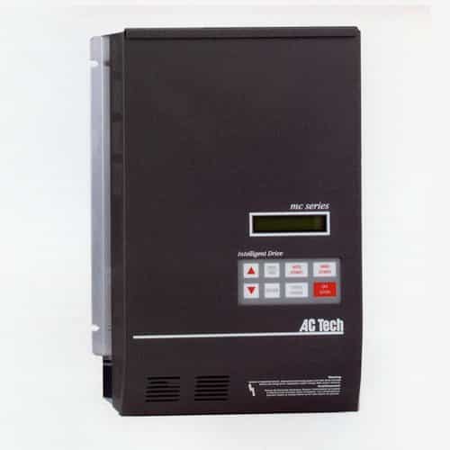 https://www.precision-elec.com/wp-content/uploads/2011/12/lenze-ac-tech-m1450b-mc-series-micro-variable-frequency-drive.jpg
500
500
Craig Chamberlin
https://www.precision-elec.com/wp-content/uploads/2025/02/Precision-Electric-Logo-TEXT-ONLY-Color-NEW.png
Craig Chamberlin2011-12-14 11:43:032018-02-20 13:02:04Lenze AC Tech MC Series Variable Frequency Drive
https://www.precision-elec.com/wp-content/uploads/2011/12/sewage-treatment-plant.jpg
331
500
Preston Dodd
https://www.precision-elec.com/wp-content/uploads/2025/02/Precision-Electric-Logo-TEXT-ONLY-Color-NEW.png
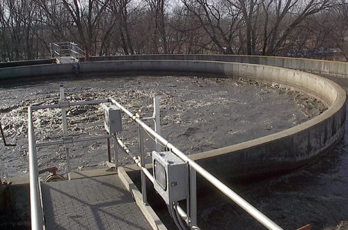
Preston Dodd2011-12-13 13:21:422017-12-12 11:54:48Industrial Pump Repair
https://www.precision-elec.com/wp-content/uploads/2011/12/lenze-ac-tech-m1450b-mc-series-micro-variable-frequency-drive.jpg
500
500
Craig Chamberlin
https://www.precision-elec.com/wp-content/uploads/2025/02/Precision-Electric-Logo-TEXT-ONLY-Color-NEW.png
Craig Chamberlin2011-12-14 11:43:032018-02-20 13:02:04Lenze AC Tech MC Series Variable Frequency Drive
https://www.precision-elec.com/wp-content/uploads/2011/12/sewage-treatment-plant.jpg
331
500
Preston Dodd
https://www.precision-elec.com/wp-content/uploads/2025/02/Precision-Electric-Logo-TEXT-ONLY-Color-NEW.png
Preston Dodd2011-12-13 13:21:422017-12-12 11:54:48Industrial Pump Repair


