

When someoneneeds to runa three phaseelectric motor and only single phase power is available, they look for a solution. There are a couple options to go from single phase power to three phase. This article will discuss options available for going fromsingle phase power to three phase., pros and cons for each option, and,links to our website for products that will go from single phase power to three phase. There are two different methods to go from single phase power to three phase:
When going from single phase power to three phase, either avariable frequency drive or rotary phase converteris required. Variable frequency drivescome with a number of differentsingle phase input for three phase output options.Variable frequency drives that go from single phase power to three phase are availablein a wide range of voltage and power ratings: From120 Volt single phase input for 240 Volt three phase output, up to 1.5 horsepower; To208-240 Volt single phase input for 240 Volt three phase output, up to 3 horsepower.
Variable frequency drivescan also be derated to run three phase motors above 3 HP from single phase supply. Derating a VFDallows customers with 208-240 volt single phase power the ability to run 240 volt three phase equipment. Derated VFD’s are available up to 20 HP for 208-240 Volt single phase supply. Derating a VFD incorrectly for single phase supply can be easily avoided by contacting an experienced technician before purchasing equipment.
Rotary phase converters (RPCs) will change single phase power to three phase but RPC’s are heavy and use many moving parts. RPC’s are old technology but RPC’s will be around for years to come because some applications that go from single phase power to three phase cannot use a VFD; VFD’s can go from single phase to three phase forelectric motor driven applications; but RPC’s can go from single phase to three phase on applications with and without electric motors.
Single phase motors cannot be used on variable frequency drives. When customers with single phase motors wantto control the speed of their electric motor, the only option available is to replace the single phase motor with an equivalent three phase motor, and then apply a variable frequency drive to that three phase motor.For VFD and RPC repair and replacement quotes, contact Precision Electric.

A VFD speed controller is also known as a variable frequency drive, variable speed drive, adjustable frequency drive, VFD or, aninverter.
A VFD speed controller is asolid state electric motor control system, designed to control the speed of an electric motor. A VFD speed controller can reduce energy costsup to 50% by speed reduction on electric motorswhere the full speed of the electric motor is not needed. VFD speed controller functions allow an AC electric motor to only operate when needed, which allows an electric motor to last longer.Technology has allowed VFDs to reduce in cost and physical size, and has improved performance through advances in semiconductor switching devices, simulation, control techniques, control hardware, and software.
Approximately one third of electrical energy in the world is supplied by electric motors in fixed-speed centrifugal pump, fan, and air compressor applications. These fixed-speed applications do not usually require full load speed of the electric motor theyre operating. By installing a VFD speed controller to these applications, electric motor speeds are reduced and power costs can be reduced by 50% or more.Properly applied VFD speed controllers withelectric motorswill also significantly reduce energycosts for variable torque loads such as fans, blowers, and pumps.Blowers are often used with dampers to control air flow that operate either manually or automatically. When dampers are closed, 50% of the electric motor current will drop to approximately 60% of full load nameplate current. By utilizing VFD speed controllersin blower applications, the current draw of the motor will be reduced 30% for every 10% drop in speed. Electric motors controlled by VFD speed controllersat 50% speed will draw approximately 20% of the electric motor full load current.
VFD speed controllersare also used on rotating equipment toreduce amperage spikes upon start up of large electric motors.Adjusting the acceleration and deceleration time of electric motors can extend the lifespan of an electric motor. Using a drive on an electric motor provides the ability to increase or decrease the frequent starting and stopping of an AC electric motor. Limiting the starting and stopping of a motor, and controlling the ramp up and ramp down speed of amotor, allows for decreased wear and extended lifetime of the motor. VFD speed controllers are used in AC servo systems, air compressors, conveyor systems, lathes, mills, plastic extrusion, slitter lines, bottlers, packaging lines, pharmaceutical production, food processing, HVAC systems, waste water treatment systems, submersible pumps, fans, blowers, and many more electric motor applications.
To learn more about VFD speed controllers, or, for drive repair and replacement quotes, contact Precision Electric, Inc.

This article has been revised and re-posted here. If the link doesn’t work, please copy and paste the following into your browser:
https://www.precision-elec.com/allen-bradley-servo-motor-repair
Allen Bradley servo motor repair is less expensive than Allen Bradley servo motor replacement. Trained technicians should perform Allen Bradley servo motor repair. Technicians undergo unique testing procedures on Allen Bradley servo motors that are dependent upon their model, features, operations, and prints. Allen Bradley servo motor repair should initially be inspected for cosmetic damage. Taking photos of the servo motor prior to further processing is suggested.
Servo Motor nameplate data and preventative maintenance info should be collected by the repair technician and safely stored for future reference. Once these initial steps are complete, the servo motor should be meter tested before test running on a control panel; Meter testing prevents further damage to parts, winding, and insulation. The servo motor should then beconnected to a test stand to check EMF (electromagnetic frequency), encoder or resolver feedback, and commutation alignment; These standard tests are to ensure functionality oncethe motor is installed forproduction. Servo motors also need to be tested with an oscilloscope to create an operation print. Once an operation printout is generated, a technicianwill check for connection issues, magnet failure, winding failure, and perform a 100% component test.
Once the technician finishes making repairs, they will then reassemble for final testing. During the final test procedure, technicians should connect the motor to an inverterwith and without a load. Running the servo motor on an inverter is to ensure complete functionality. Testing with an inverter also allows verification that the servo can operate at full voltage and withstand full load amps of motor specifications. Repair shops should work closely with all servo motor manufacturers. Working closely with servo motor manufacturers allows for access to servo motor data sheets. Repair technicians use data sheets to ensure that the servo motor performs equal to, orbetter than, the original manufacturer standards.
Most repair shops offering Allen Bradley servo motor repair do not even perform the repair in their facility. Instead, these repair shops outsource the repair to a third party such as Precision Electric. Using a third party repair shop is risky, more expensive, and has a longer lead time than going directly to the repair source.Allen Bradley servo motor repair from Precision Electric includes a 12 month in-service warranty. For Allen Bradley servo motor repair and replacement quotes, contactPrecision Electric.
Indramat servo motor repair is less expensive than Indramat servo motor replacement. Indramat servo motor repair should only be performed by an electrical technician with training and experience.Most Indramat servo motors have unique testing procedures dependent upon their model, features, operations, and prints; But the general process is performed by a technician who follows standard test procedures. Technicians performing Indramat servo motor repair should go through an extensive evaluation process to ensure nothing is overlooked. Servo motor repairs should be initially inspected for cosmeticdamage and taking photos prior to further processing is suggested.
All nameplate and preventative maintenance info should be collected by the repair technician and safely stored forfuture reference. Once these initial steps are complete, the Indramat servo motor should be meter tested before test running on a control panel; Meter testing is to prevent further damage to parts, winding, and insulation. The servo motor should then be connected to a test stand to check EMF (electromagnetic frequency), encoder or resolver feedback, and commutation alignment; These standard tests are to ensure functionality once the motor is installed into production.Servo motor repairs also need to be tested with an oscilloscope to create an operation print. Once an operation printout is generated, the technicianwill check for connection issues, magnet failure, winding failure, and perform a 100% component test.
IndramatServo Motor Repair – Steps
Once testing is complete, the servo motor technician reassembles the unit for final testing. During the final test procedure, techniciansshould connect the motor to an inverter drive with and without a load. Running the servo motor on an inverter is to ensure complete functionality beforereturning to customer. Final testing of servo with an inverter also allows verification that the servo motor can operate at full voltage and withstand full load amps of the motor specifications.It’s also suggested that repair shops work closely with all servo motor manufacturers. Working closely with servo motor manufacturers allows foraccess todata sheets that are needed to ensure that the the servo motor performs equal to, or better than, the original equipment manufacturer standards.
Some repair shops only require technicians to perform a few of these procedures but all of them are suggested by Precision Electric. Most repair shopswho offer Indramat servo motor repair do not even perform the repair in their facility; Instead, they outsource the repair to a third party such as PrecisionElectric. Precision Electric recommends technicians who areinvolved in repair decisions, verify thatthe company you’re sending equipment to is the same company who performs the repair. Using a third party Indramat servo motor repair shop is risky, more expensive and has a longer lead time than going directly to the repair source.
Servo motor repairs performed by Precision Electric includes a 12 month in-service warranty. The PrecisionElectric in-service warranty begins the day the servo motor is put into production and ends 12 months later.
For more information on Indramat servo motor repair and replacement, contact Precision Electric.

How AVFD Works:A variable frequency drive is also known as a VFD, variable speed drive, adjustable speed drive, electronic motor controller, or an inverter. How a VFD Works: Every VFD is unique with its own component characteristics so how each VFD works is dependent upon components within the VFD. Most VFDs integrate a solid state electronics controller consisting of a bridge rectifier, a converter, and an inverter module.
Voltage-source inverter drives are the most common type of VFDs. These drives convert AC line input to AC inverter output.There are some applications that use common DC bus and solar applications. These type of drives are configured as DC to AC drives. The bridge rectifier converter for volts per hertz drives is configured for 3 phase AC electric motors. Volts per hertz drives usea capacitor to smooth out the converter DC output ripple and provides a solid input to the inverter.
This filtered DC voltage is converted to AC voltage output using the inverter’s active switching elements. VSI drives provide higher power factor and lower harmonic distortion (noise) than phase controlled current source inverters and load commutated inverters drives. The drive controller can also be configured as a phase converter having single-phase converter input and three-phase inverter output.Controller advances have allowed increased voltage and current ratings and switching frequency of solid-state power devices over the past 50 years. VFDs were first introduced in 1983, and the insulated gate bipolar transistor has in the past 20 years become the standard for VFDs as an inverter switching device.
In variable-torque applications using Volts per Hertz (V/Hz) drive control, AC motor specifications require that the voltage magnitude of the inverter’s output to the motor be adjusted to match the required load torque in a corresponding V/Hz relationship. For 460 VAC, 60 Hertz electric motors, this V/Hz relationship would be 460/60 = 7.67 V/Hz. While acceptable in a wide range of different applications, V/Hz control is sub-optimal in high performance applications. High performance applications requiring low speed control, demanding high torque, dynamic speed regulation, positioning, and reversing load demands, there are open loop VFDs and closed loop VFDs would be desired over V/Hz VFDs.
How a VFDWorks – Manufacturing
Many manufacturers will apply variable frequency drivesto rotating equipment to reduce amperage spikes upon start up of large electric motors. Choosing the right VFD for an application will benefit rotating equipment by providing less wear on the electric motors where applied. Adjusting the acceleration and deceleration time of electric motors can extend the lifespan of an electric motor. Variable frequency drives provide the ability to control the frequency of starting and stopping of an AC electric motor. This ability allows an AC electric motor to only operate when needed for the equipment its rotating, and electric motors have a longer lifespan if they are only running when they need to be.
Approximately one third of the worlds electrical energy is supplied by electric motors in fixed-speed centrifugal pump, fan, and air compressor applications. These fixed-speed applications hardly ever require the full load speed (RPM) of the electric motor in which theyre operating. By installing a VFD to these applications, electric motor speeds are reduced, and power costs can be reduced by 50% or more. Technology has allowed cost and physical size reduction of variable frequency drives, and has improved performance through advances in semiconductor switching devices, simulation, control techniques, and control hardware and software.
How a VFDWorks – Power Savings
The majority of variable frequency drives in the market today contain electronic circuitry that converts 60 Hertz Line power into direct current. The variable frequency drive converts this line power into a pulsed output voltage that duplicates varying alternating current to a desired frequency (speed). A properly applied VFD when paired with the correct electric motor will significantly reduce operating costs for manufacturers. This is particularly true for variable torque loads such as fans, blowers, and pumps. Blowers are often used with dampers to control air flow; these dampers may operate either manually or automatically. When dampers are closed, 50% of the electric motor current will drop to approximately 60% of full load nameplate current. By utilizing variable frequency drives in blower applications, the current draw of the motor will be reduced 30% for every 10% drop in speed. The same electric motor operating from an AC variable frequency drive at 50% speed, will draw approximately 20% of the full load current.
Please watch our YouTube Videoto learn more about how a VFD works.For VFD repair and replacement quotes, contact Precision Electric, Inc.

Servo motor repairs areless expensive and quicker than servo motorreplacements.Servo motorrepairs should be taken with extreme caution and only be performed by technicians who have training and experience to work with electrical equipment. Most companies who offer servo motorrepairs do not even perform the repair in their facility; instead, these companies outsource the repair to a third party such asPrecision Electric. Precision Electric always receives servo motorrepairs from companies who offer servo motorrepair services. Third party repair companies take longer to return equipment to their customers and third party repair companies mark up the repair cost to their customers. Precision Electric recommends verifying that the company offering repair services is the company actually repairing the equipment.
Servo motor repairs should always go through an extensive evaluation process to ensure nothing is overlooked.The servo motor should be connected to a test stand to check back emf, encoder or resolver feedback, and commutation alignment to ensure functionality once the motor is installed into productions. Servo motor repairs need tobe tested with an oscilloscope andonce an operation printout is generated, the technician will check for connection issues, magnet failure, winding failure, and 100% component testing. Servo motor repairs at Precision Electric are initially inspected for cosmetic damage and then they are meter tested before test running on a control panel. Most servo motor repairs have unique testing procedures dependent upon the manufacturer operations and prints, but the general process follows standard testprocedures.
It’s also necessary for Precision Electric to work closely with all servo motor manufacturers. Working closely with servo motor manufacturers allows Precision Electric access to technical data sheets that are neededto ensure that the the servo motor performs optimally prior to shipping the repaired unit back to customer.
Precision Electric standard servo motor repairs are subject to:
After servo motor repairs and preliminary testing are complete, the servo motor is reassembled for final testing. Servo motor repairs are not complete until after final testing procedure is performed. During the final test procedure, servo motors should be connected to an inverter drive with and without a load, to ensure functionality before returningto customer. Final testingalso allows verification that the servo motor can operate at full voltage and withstand full load amps of the motor specifications.
Servo motor repairs should only be performed by facilities that work closely with all servo motor manufacturers so that the newest servo drives are being used in conjunction with theircorresponding servo motors.Precision Electric recommends all manufacturers keep spare servo motors on crucial production lines. Keeping a spare can minimize downtime and prevent production losses while repair services are being processed. Servo motor repairsperformed by Precision Electric includes a 12 month in-service warranty. The Precision Electric in-service warranty begins the day the servo motor is put into production and ends 12 months later.
For pricing on servo motor repairs andservo motorreplacements, contact Precision Electric.

Variable frequency motor drives are also known as motor drives,variable frequency drives, VFD’s, variable speed drives, adjustable frequency drives, AFD’s, adjustable speed drives and ASD’s. Motordrives are solid state motor control systems used to regulatethe speed of alternating (AC) electric motors. Motordrives are mainly used to reduce energy consumption on electric motors for industrial manufacturers.
Motordrives operate as load controls within applications that may accomplish up to 50% reduction in energy costsby speed reduction on applications where the full speed (RPM) of the electric motor is not required. Motor drives are used in AC Servo Systems, Air Compressors, Conveyor Systems, Lathes, Mills, Plastic Extrusion, Slitter Lines, Food Processing, Waste Water Treatment Systems, Submersible Pumps, HVAC Fans and Blowers, and many more AC motor applications.
Many manufacturers apply motor drives withrotating equipment toreduce amperage spikes upon start up of large electric motors.Choosing the right motordrive for an application will benefit rotating equipment by providing less wear on the electric motor where applied. This is accomplished by adjusting the acceleration and deceleration time of electric motors. Adjusting the acceleration and deceleration time of an electric motor will greatly increase the lifespan of an electric motor. Motor drives provide the ability to control the frequency of starting and stopping of an AC electric motor.This ability provides a means by which an AC electric motor is only operating when needed for the equipment it’s rotating, and electric motors have a longer lifespan if they are not continuously operating when they don’t need to be.
Approximately one third of the world’s electrical energy is supplied by electric motors in fixed-speed centrifugal pump, fan, and air compressor applications. These fixed-speed applications hardly ever require the full load speed (RPM) of the electric motor they’re operating. By integrating motor drives to these applications, the motor speeds are reduced, and power costs can be reduced by 50% or more. Technology has reduced cost and physical size of motordrives, and has improved performance through advances in semiconductor switching devices, simulation, control techniques, and control hardware and software.
The majority of motordrives in the market today contain electronic circuitry that converts 60 Hertz Line power into direct current. The motordrive converts this line power into a pulsed output voltage that duplicates varying alternating current to a desired frequency (speed).A properly applied motordrive when paired with an AC electric motor, will significantly reduce operating costs. This is particularly true for variable torque loads such asFans,Blowers, andPumps.Blowers, for example, are often used with dampers to control air flow. These dampers may operate either manually or automatically. When dampers are closed, 50% of the electric motor current will drop to approximately 60% of Full Load nameplate current. By utilizing a motor drive in this application, current draw in the motor will be reduced 30% for every 10% drop in speed. The same electric motor operating froma motor drive at 50% speed, will draw approximately 20% of the full load current.
Volts Per Hertz motordrives are the most common type of drive and areknown as a V/Hz drives, or volts by hertz drives. V/Hz motordrives are used inapplications such as fans, pumps, air compressors, and other related applications wherehigh starting torque is not required. V/Hz drive applications typically do not require full torque when the AC motor is operating at less than the base speed (RPM) of the electric motor. V/Hz drives are the most inexpensive type of motor drive. V/Hz drives do not provide full motor torque at low RPM.
Open-Loop vector motordrives are also known as “sensorless vector” drives. Open loop vector drives adapted the name “sensorless vector” because they do not use an external encoder for speed feedback to the motor.Open loop vector drives are used in applications where high starting torque and full torque at low speed (RPM) is required. Open-Loop vector drives operating a motor a zero RPM should not be used on crane or hoist applications. Most open-loop vector drives are used on CNC machines, mixers, mills, lathes, and other applications where high starting torque or full torque at low RPM is needed.Open loop vector drives are usually more expensive than V/Hz inverterdrives.
Closed-Loop vector motor drives are used in applications where precise speed control (0.01%) is needed, or in applications where extensive programming is needed. Closed-Loop vector drives use an encoder on the motor to provide constant shaft position indication to the drive’s microprocessor. The encoder feedback allows the drive microprocessor to constantly control torque no matter how many RPM the motor is operating at. Closed-Loop vector motor drives are used to provide the motor to operate at full torque even at zero RPM. Closed-Loop vector drives are commonly used on hoist and crane applications because crane and hoist motors must produce full torque prior to it’s brake being released, or the load will drop and it will not be able to stop.
To learn more about motordrives or for motordriverepairs and replacement quotes, contact Precision Electric, Inc.
Most inverterrepair can be prevented with routine maintenance. Inverter repair costs and lead times can also be reduced with routine maintenance. Inverterrepair can be expensive and also cost manufacturers production downtime while the inverter repair is in process.Most manufacturers stock spare inverter modulesto prevent production downtime in the event of an inverter failure.Components used forinverter modules are often cheaply made and prone to failure. Knowledgeable inverter repair shops should replace cheaply made components with high quality components during the inverter repair process. Using high quality components in an inverter repair ensures a higher chance of success and a longer lifespan during production.
Connections
Checkingconnections is a step many people miss or do incorrectly during the inverterrepair process. Heat cycles and mechanical vibration can lead to sub-standard connections, as can standard preventative maintenancepractices. Reusing torque screws is not a good Idea, and further tightening an already tight connection can ruin the connection.Bad connections eventually lead to arcing. Arcing at the inverterinput could result in nuisance over voltage faults, clearing of input fuses, or damage to protective components. Arcing at the inverteroutput could result in over-current faults or even damage to the power components.
Loose connections can cause erratic operation. Loose START/STOP signal wires can cause uncontrollable inverterstarting and stopping. A loose speed reference wire can cause the drive speed to fluctuate, resulting in scrap, machine damage, or personnel injury.
Conduct Diode and IGBT Tests
There are a number of methods to test the input and output power sections of an inverter, and this step is essential prior to applying power to the inverterunit. If for any reason there is a short on the input side or output side of the inverter, further damage can be caused to the unit if power is applied to it.
For this reason, Precision Electric uses meters to properly test the input and output power sections of the inverter prior to applying power to the actual unit. If a short is found, the unit can be disassembled and the cause of the short can be diagnosed and quoted for repair. If the repair is too costly, then a replacement is offeredto the customer.
Power Up Unit
If the input and output power sections test healthy during this step of the inverter repair process, Precision Electric will power the unit and perform amp reading and output frequency tests. Precision Electric prefers to slowly increase power voltage to the unit until the rated input voltage of the inverter is achieved.
Depending on whether or not the inverter provides a display will determine what further action(s) will be taken. If display is unavailable, dis-assembly and diagnosis of the internal power supply of the control section of the inverter is likely necessary to further evaluate cause of failure and establish costand lead time for the inverter repair.
Run A Motor
If the previous three tests have passed during the inverter repair process, then it is time to run a basic jog function of the inverter with a simple template program. Often when an inverter comes into our facility, we make sure to backup whatever program is currently stored in the inverterprior to inputting a template program and running a test procedure. This ensure we have a backup copy of the program.
The best method for backing up depends on the brand of drive, but after it has been backed up, we either reset the inverterto factory defaults through the keypad and recommission a basic start, stop and job application or closed loop if an encoder is involved. If the motor will not run, it will be necessary to checkthe output voltages and current ratings going to the motor to see if the inverteris functioning properly to rotate the motor.
Contact Customer
At this point we have determined the cause of failure, estimated lead time and costof the inverterrepair. If the inverter has tested good entirely, then further underlying issues are communicated with the customer. This is when Precision Electricwill gather application specific information from the customer to establish whether or not it may be some outside issue associated with the system including, but not limited to, PLC communications, faulty IO, bad wiring or even bad cabling. There is no single way to do this step, as it really depends on a wide variety of variables.
Send Service Tech
If the customer cannot establish failure on any other aspect of the machine and the inverterappears to test fine, then it may be necessary to send a field service technician on site to establish cause of failure. Field service technicians should betrained to troubleshoot any issue ranging from standard inverterrepair, to advanced robotics, PLCs and more. Field technicians should also be trained to establish cause of failure and come up with solutions as quick as possible.
Inverter repair should be taken with extreme caution. Inverterrepair should only be performed by technicians who have required training and experience to work with electrical equipment. Precision Electric strongly recommends to consult an expert in the field when repairing or installinginverterequipment.Many invertercontrollers have an internal DC bus that retains a charge after power has been cut to the drive, as a result, it does not mean it’s safe to work with. Technicians working with inverter repair must always take extra precautions to ensure proper safety measures are taken, or injury or even death may occur.
For inverterrepair and inverter replacement quotes, contact Precision Electric.
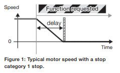 ABB ACS355 emergency stop is usedfor applications that require risk reduction from unexpected and hazardous movement. The aim to integrate drive-based safety functions is to createmachines that are safe to use. This safety function example is presented to install ABB ACS355 emergency stop but these same functions can be implemented with other ABB drives with few modifications. ACS355 machinery drives offer a safe torque off (STO) safety function as a standard integrated feature. STO eliminates the need to use contactors, which means that the drive is not disconnected from the power during safe stopping. This again enables fast restart of the drive and the machine. STO is also offered as standard in many ABB drive types for easy integration of functional safety.
Overview of the Safety Function
ABB ACS355 emergency stop, stop category 1 (Figure 1), stops the drive with a controlled deceleration ramp before disabling the drives output to the motor. In this example, the deceleration ramp is time monitored. The safety function can be used in an application where a synchronized stop of multiple axes is required.
Design of the Safety Function
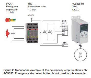 The design of theABB ACS355emergency stop consists of an emergency stop button as an activating switch, a safety timer relay as a logic unit and a safe torque off (STO) -circuit inside the ACS355 drive. The drive acts as an actuator to bring the motor into a nontorque state after the deceleration. See circuit diagram (Figure 2) for connection details.
Operation of the safety function When the emergency stop button is pressed, the safety relay detects the button signal and opens its non-delayed contacts to inform the drive todecelerate. Simultaneously, the relays timer for the time delay contacts starts counting. After the time delay has elapsed, the contacts open, activating the STO function, which disables the drives power output to the motor. To continue drive operation after an emergency stop, the emergency stop button is released (pulled up), which causes the contacts of the relay to close. This deactivates the STO function. The drive is restarted by a separate start command. The drive is configured not to start automatically.
The safety relay is used to provide diagnostics for the emergency stop button wiring. The relay also enables the use of a separate reset button, if required (reset button is not shown in this example since it is not required by the standard). Ensuring the required safety performance The safety function has to fulfil the required safety performance determined by a risk assessment. ABBs Functional safety design tool (FSDT-01) is used to design the desired safety function.
This is carried out according to the Following Steps:
1. Evaluate the risks to establish target safety performance (SIL/PL level) for the safety function.
2. Design the safety function loop and verify the achieved performance (PL) or safety integrity level (SIL) for the safety function loop (according to EN ISO 13849-1 or EN/IEC 62061, respectively), utilizing the device safety data and the application specific characteristics.
3. Generate a report for the machine documentation. Report should contain all the calculation results as well as all assumptions made during the application design.
Safety function verification and validation In addition to the safety calculations for the achieved safety performance (SIL/PL), the safety function needs to be functionally verified as well. Finally the implemented safety function is validated against the risk assessment to ensure that the implemented safety function actually reduces the targeted risk.
General considerations Achieving machinery safety requires a systematic approach beyond the physical implementation of a safety function. The overall machinery safety generally covers the following areas:
For more information concerning the ABBACS355 emergency stop function, visit the ABB Website.For ABB drive repair quotes or ABB drive replacement quotes, contact Precision Electric.

A VFD (variable frequency drive) controls the speed, torque and direction of an induction motor. A VFD takes fixed motor voltage and AC frequency and converts it to a variable voltage and frequency AC output. In very small VFDs, a single power pack unit may contain the converter and inverter modules. Preventive maintenance VFD programs preventmanufacturing downtime while maintaining optimal production performance.
Most VFDs fall into the NEMA 1 category or NEMA 12 category. Drives that fall in the NEMA 1 category are susceptible to dust contamination. Dust on VFD hardware can cause a lack of airflow resulting in diminished performance from heat sink and circulating fans. Dust on an electronic device can cause malfunction or even failure. Dust absorbs moisture, which also contributes to failure. Periodically spraying air through the heat sink fan is a good PM measure. Discharging compressed air into a VFD is a viable option in some environments, but typical plant air contains oil and water. To use compressed air for cooling, you must use air that is oil-free and dry or you are likely to do more harm than good. A non-static generating spray or a reverse-operated ESD vacuum will reduce static build-up. Common plastics are prime generators of static electricity. The material in ESD vacuum cases and fans is a special, non-static generating plastic. These vacuums, and cans of non-static generating compressed air, are available through companies that specialize in static control equipment.
Control boards and other electronic components can be damaged when subjected to periodic moisture or water. Some VFD manufacturers include a type of condensation protection on certain product versions. If you operate a VFD all day every day, the normal radiant heat from the heat sink should prevent condensation. Unless the unit is in continuous operation, use a NEMA 12 enclosure and thermostatically controlled space heater where condensation is likely.
Checking connections is a step many people miss or do incorrectly, and the requirement applies even in clean rooms. Heat cycles and mechanical vibration can lead to sub-standard connections, as can standard PM practices. Reusing torque screws is not a good Idea, and further tightening an already tight connection can ruin the connection.
Bad connections eventually lead to arcing. Arcing at the VFD input could result in nuisance over voltage faults, clearing of input fuses, or damage to protective components. Arcing at the VFD output could result in over-current faults or even damage to the power components.
Loose connections can cause erratic operation. For example, a loose START/STOP signal wire can cause uncontrollable VFD starting and stopping. A loose speed reference wire can cause the drive speed to fluctuate, resulting in scrap, machine damage, or personnel injury.
You wouldn’t place alaptop computer on the roof of a building or in direct sunlight, where temperatures could reach 115 degrees Fahrenheit or as low as -10 degrees Fahrenheit. A VFD, which is basically a computer with a power supply, needs the same consideration. Some VFD manufacturers advertise 200,000 hours-almost 23 years-of Mean Time between Failures (MTBF). Such impressive performance is easy to obtain, if you follow these simple procedures.
By integrating a preventive maintenance VFD program, you can ensure your drives provide minimal repair service while maximizing production.Always call certified variable frequency drive integrators or experienced technicians to perform preventive maintenance VFD services to prevent injury or death.
To learn more about preventive maintenance VFD programs or for VFD repair and replacement quotes, contact Precision Electric.
What is a variable frequency drive? Variable frequencydrives are also known as variable speed drives, VFD’s, adjustable speed drives, and inverters.
Variable frequency drives are solid state motor control systems designed to control the speed of an AC (alternating current) electric motor. Variable frequency drives operate as load controls within AC electric motor applications; and variable frequency drives can reduce energy costsup to 50% by speed reduction on electric motorswhere the full speed (RPM) of the electric motor is not required.Variable frequency drives are used in AC servo systems, air compressors, conveyor systems, lathes, mills, plastic extrusion, slitter lines, food processing, waste water treatment systems, submersible pumps, HVAC fans and blowers, and many more electric motor applications.
Many manufacturers apply AC variable frequency drives to rotating equipment because variable frequency drives reduce amperage spikes upon start up of large electric motors.Choosing the right AC variable frequency drive for an application will benefit rotating equipment by providing less wear on the electric motors where applied.Adjusting the acceleration and deceleration time of electric motors can extend the lifespan of an electric motor. AC variable frequency drives provide the ability to control the frequency of starting and stopping of an AC electric motor.This ability allowsan AC electric motor to only operate when needed for the equipment it’s rotating, and electric motors have a longer lifespan if they are not continuously operating when they don’t need to be.
Approximately one third of the world’s electrical energy is supplied by electric motors in fixed-speed centrifugal pump, fan, and air compressor applications. These fixed-speed applications hardly ever require the full load speed (RPM) of the electric motor in which they’re operating. By installing AC variable frequency drives to these applications, electric motor speeds are reduced, and power costs can be reduced by 50% or more. Technology has allowed cost and physical size reduction of AC variable frequency drives, and has improved performance through advances in semiconductor switching devices, simulation, control techniques, and control hardware and software.
The majority of AC variable frequency drives in the market today contain electronic circuitry that converts 60 Hertz Line power into direct current. The variable frequency drive converts this line power into a pulsed output voltage that duplicates varying alternating current to a desired frequency (speed).A properly applied AC variable frequency drive when paired with an AC electric motor will significantly reduce operating costs for manufacturers. This is particularly true for variable torque loads such as fans, blowers, and pumps.Blowers are often used with dampers to control air flow; these dampers may operate either manually or automatically. When dampers are closed, 50% of the electric motor current will drop to approximately 60% of full load nameplate current. By utilizing an AC variable frequency drive in blower applications, the current draw of the motor will be reduced 30% for every 10% drop in speed. The same electric motor operating froman AC variable frequency drive at 50% speed, will draw approximately 20% of the full load current.
Example Application:
A 10 horsepower AC electric motor, rated 90% efficient, operating across the line without an AC variable frequency drive, with the dampers operating between 50 70%, for 2000 hours per year will require 11,996 KWH. If the KWH charge is $.08 per KWH, the cost to run this motor will be: $1,248.00 annually.The same 10 horsepower electric motor operating from an AC variable frequency drive, between 50 70% speed for 2000 hours per year will require 4,676 KWH. Operating cost at the same KWH rate will be: $432.00 per year. This represents a savings of $816.00 per year and should be enough to pay for the AC variable frequency drives investment and installation costs, within the first 12 months of operation.If any electric motor application operates more hours than in the above example, and/orthe KWH charge is higher, the savings will quickly compound.The energy saved on a utility bill from using a variable frequencydrive is often significant enough to pay for the variable speed frequencywithin a couple of months from installation date.Increasing and/or decreasing the start up time on an AC current electric motor via a variable frequencydrive can add years to the motor’s overall lifespan. Using a variable frequencydrive can also improve efficiency on production demands. Variable frequencydrives provide the ability to control the frequency of starting and stopping an AC electric motor.This ability provides a means by which an AC electric motor is only operating when needed. AC electric motors have a longer lifespan if they are not continuously operating when they do not need to be.
Volts Per Hertz drives are the most common type of variable frequency drive and areknown as a V/Hz drives, or volts by hertz drives. V/Hz variable frequency drives are used inapplications such as fans, pumps, air compressors, and other related applications wherehigh starting torque is not required. V/Hz variable frequencydrive applications typically do not require full torque when the AC motor is operating at less than the base speed (RPM) of the electric motor. V/Hz variable frequencydrives are the most inexpensive type of variable frequencydrive. V/Hz variable frequencydrives do not provide full motor torque at low RPM.
Open-Loop vector drives are also known as “sensorless vector” variable frequencydrives. Open loop vector drives adapted the name “sensorless vector” because they do not use an external encoder for speed feedback to the motor.Open loop vector drives are used in applications where high starting torque and full torque at low speed (RPM) is required. Open-Loop vector drives operating a motor a zero RPM should not be used on crane or hoist applications. Most open-loop vector drives are used on CNC machines, mixers, mills, lathes, and other applications where high starting torque or full torque at low RPM is needed.Open loop vector drives are usually more expensive than a V/Hz variable speed drives.
Closed-Loop vector drives are used in applications where precise speed control (0.01%) is needed, or in applications where extensive programming is needed. Closed-Loop vector drives use an encoder on the motor to provide constant shaft position indication to the drive’s microprocessor. The encoder feedback allows the drive microprocessor to constantly control torque no matter how many RPM the motor is operating at. Closed-Loop vector drives are used to provide the motor to operate at full torque even at zero RPM. Closed-Loop vector drives are commonly used on hoist and crane applications because crane and hoist motors must produce full torque prior to it’s brake being released, or the load will drop and it will not be able to stop.
To learn more about variable frequency drives or for repair and replacement quotes, contact Precision Electric, Inc.


