Eaton power board failure

This article has been updated and re-posted athttps://www.precision-elec.com/eaton-power-board-failure-2-2/

Eaton power board failure is a common problem among Eaton drive users. The main reason most Eaton drives fail is due to power board or control board failure. Power board failure is usually caused from either Eaton drivesreaching the end of their life cycle orneglecting preventativemaintenance of Eaton equipment. Eaton power boards can be repaired by Eaton Corporation but Eaton takes a long time to diagnose and repair equipment. Most of the time Eaton will hold onto a manufacturer’s drive for months and then tell them that the drive must be replaced because “it isn’t worth repair”. Precision Electric has repaired many Eaton power boards and drives over the years that Eaton deemed “not repairable”.

Eaton power board failure repair services are also offered by Eaton drive distributors but most Eaton drive distributors don’t even repair the drives themselves. Most Eaton drives distributors outsource Eaton drive repair because they don’t have the equipment or technical staff to perform Eaton drive repair Going through an Eaton distributor who is sending the repair to a third party is cost prohibited and takes too long for the drive user. Precision Electric performs all Eaton power board repair in house and offers emergency repair for breakdowns that require immediate service.

The Eaton power board failure repair process should always be taken with extreme caution. Eaton power board failurerepair should only be performed by technicians who have required training and experience to work with electrical equipment. Troubleshooting and repairing an Eaton power board is time consuming and tedious because every Eaton power board can be unique depending upon the Eaton drive functions and capabilities; But, the overall structure of troubleshooting and repairing always remains the same.The ultimate goal when repairing an Eaton power board is to diagnose the cause of failure, repair the power board, and re-commission the unit, as quickly as possible.

Precision Electric performs all Eaton power board failure repairs in house. In house repair ensures efficient turnaround time and repair cost to Eaton drive users. Precision Electric also offers Eaton power board failure emergency repair services for customers who are broke down andrequire immediate repair services.

To learn more about Eaton power board failure or for Eaton power board repair quotes, contactPrecision Electric, Inc.


Electric Motor Service Factor

What does the electric motor Service Factor really mean?

The nomenclature of service factor on an electric motor nameplate is designated by “S.F.”. Service factor is a multiplier, which when applied to the rated horsepower, gives the allowable horsepower loading the machine is capable of delivering without causing significant damage to the unit.

Electric motor service factor is not a direct multiplier to motor current but it is a good rule to follow since horsepower output is often proportional to current draw.For most motors, using the service factor multiplier on the nameplate to the full load current rating will provide an accurate assessment of allowable full load current.There are some exceptional cases in which this rule may not apply. Operating an older until with lower efficiency ratings or operating in conditions in which power factoris low will create less temperature increase per ampere than in modern ‘T’ frame motors will heat up dramatically when operated over full load nameplate current ratings.

The key to maximum allowable current draw is how the draw in excess of nameplate will affect core heating and the ability of the core to dissipate that heat. Electric motor service factor should never be engineered into an application. Electric motors should never be operated within their service factors for prolonged time periods. The electric motor service factor must be viewed as insurance against motor failure during periods of temporary load or power problems.

If your electric motors are operating within service factor range, find out why. Correct the problem or at the very least, know the problem. Motors designed to operate on 460 volt systems will draw slightly higher current when operated at 480 volts. Units that have been rewound many times may have sufficient core losses to account for slightly higher current draw. These factors considered should emphasize the need for a class H insulating system on all rewinds.

To learn more about electric motor service factor or for repair and replacement quotes, contact Precision Electric.

Motor Speed Controllers

There are three general types of motor speed controllers – AC motor speed controllers, DC Motor motor speed controllers, and Eddy Current motor speed controllers.Eachtype of motor speed controller can be divided into different variations. Each type of motor speed controller system will include an electric motor and aspeed control unit. Motor speed control technology today mainly consists of solid state electronic components in a single system. Older speed controlsystems use mechanical parts that, over time, result in failure due to moving and worn parts.

AC Motor Speed Controllers

AC motor speed controllers are also known as alternating current speed controllers, adjustable speed drives, variable frequency drives, VFD’s, inverters,and micro drives. AC motor speed controllers are used in many applications such as air compressors, conveyors, injection moulding, food processing, wastewater treatment pumps, HVAC fans and blowers, and other industrial applications. Approximately one third of the world’s electrical energy is supplied byelectric motors in fixed-speed centrifugal pump, fan, and air compressor applications. This proves that energy efficiency improvement can be implementedwhere electric motors are operating without speed AC motor speed controllers.

DC Motor Speed Controllers

DC Motor Speed Controllers are also known as DC variable frequency drives, or DC drive systems. The speed of a DC motor is directly proportional to armature voltage and inverselyproportional to motor flux; either armature voltage or field current can be used to control the motor speed. DC Motors have become expensive and todaymost dc motor speed control systems have been retrofitted by pairing an AC motor with an AC motor speed controller. AC motor speed controllers are moreenergy efficient, less expensive and more available than DC motor speed controllers.

Eddy Current Motor Speed Controllers

Eddy current motor speed controllers are a combination of a fixed speed motor and an eddy current clutch. The clutch contains a fixed speed rotor and anadjustable speed rotor separated by a small air gap. A direct current in a field coil produces a magnetic field that determines the torque transmittedfrom the input to the output rotor. The controller provides closed loop speed regulation by varying the clutch current, allowing the clutch to transmitenough torque to operate at the desired speed. Speed feedback is provided by an integral AC tachometer.

Eddy current controllers are less efficient than all other types of motorspeed controllers. Nearly all eddy current controllers are obsolete today.Somemanufacturers still use eddy current motor speed controllers, but when the equipment fails, it’s expensive to repair and oftenimpossible to replace. Eddy current motor speed controllers are upgraded via replacement by pairing an AC motor with an AC motor speed controller.

For motor speed controller replacement, repair, or retrofit quotes, Contact Precision Electric, Inc.

The SMVector Series drive is one of the most cost effective and versatile choices for controlling your motors start and stop method.

6 Step Basic Setup Of An SMV Variable Frequency Drive

The SMVector Series drive is one of the most cost effective and versatile choices for controlling your motors start and stop method.

If you want complete control over every aspect of your motor, we recommend the SMVector Series variable frequency drive.

The SMVector Variable Frequency Drive is our product of choice for the majority of customer’s applications. There are a number of factors that make us consider it the best option in the market today. One reason it that it’s extremely cost effective compared to many of their competitors. The SMVector Variable Frequency Drives comes in sometimes 20% to 50% less expensive than their counterparts. Another reason to consider the SMVector Variable Frequency Drive is the ease of setup.

This post aims to show the basic setup and configuration of an SMVector Variable Frequency Drive.

1. Turn Off All Line Power

SMVector Variable Frequency Drives come in four different voltages: 120 VAC, 240 VAC, 480 VAC and 600 VAC. No matter what voltage you have it is extremely important to shut off all power prior to wiring your drive. This is extremely important to avoid injury or death. If you are umcomfortable working with these voltages we also recommend hiring a licensed contractor to do the installation for you.

2. Wire The Input Line Voltage

The second step for the basic setup of an SMVector Variable Frequency Drive is the wiring of the input line voltage. Here is a basic overview of the different wiring options for the SMV drive. If you’re running single phase, you may also benefit from reading up on how the SMVector will can be used To Run A 3 Phase Motor On Single Phase Power.

  • Single Phase, 120 VAC: Wire and fuse your hot wire to L1 and wire your neutral to N.
  • Single Phase, 240 VAC (two hot lines): Wire and fuse your two hot lines to L1 and L2 respectively.
  • Single Phase, 240 VAC (one hot line): Wire and fuse your hot line to L1 and wire your neutral to L2.
  • Three Phase, 240 VAC: Individually wire and fuse all three hot lines to L1, L2 and L3 respectively.
  • Three Phase, 480 VAC: Individually wire and fuse all three hot lines to L1, L2 and L3 respectively.
  • Three Phase, 600 VAC: Individually wire and fuse all three hot lines to L1, L2 and L3 respectively.

You will also want to reference the SMVector manual on page 16 for a diagram of how to wire it. Don’t forget to wire an earth ground to the PE terminal as well.

3. Wire The AC Motor

The SMVector Variable Frequency drive currently only support three phase motors. Wiring the motor is extremely easy as there really is only one way to do it. The reason the SMVector currently only supports three phase motors is because it is typically used in industrial applications where higher horsepower and torque is required.

Simply individually wire your motor leads to U, V and W. Don’t forget to also wire your ground wire to the PE ground terminal on the SMV.

4. Jumper The Drive Enable

For basic setup we will be running the drive directly from the keypad so we will not need any custom wiring to the control terminals. One essential thing we need, however, is to electrically enable the drive by putting in a jumper on the control terminals. In order for the drive to enable on power up place a wire jumper between terminals one and four. For a diagram see page 19 of the SMVector Users Manual.

5. Power Up The Drive

You can now power up the drive once you are confident you have wired everything correctly. On powerup the LED screen should come up for programming. At this point in time the default settings should allow you to simply press the start button on the keypad for the drive to run. If you wish to adjust the speed you can use the up and down arrows on the keypad.

6. Finish Your Setup

There are some essential parameters you should set in your SMVector to protect the motor and the drive. See them below, you will want to reference the SMVector Variable Frequency Drive operators manual when doing this. If prompted for the password when entering the parameter menu (by pressing the menu button) then you’ll need to use the arrow keys to enter the default password of 0225.

Set the following parameters to complete your setup:

  • P102 – Minimum Frequency (Speed)
  • P103 – Maximum Frequency (Speed)
  • P104 – Acceleration
  • P105 – Decleration
  • P108 – Motor Overload (Important for Motor Protection)
  • P110 – Start Method (If you want to start on power up)
  • P111 – Stop Method (If you want to coast or ramp to stop)
  • P112 – Rotation (If you want to change direction)

Conclusion:

The SMVector is capable of very advanced features including sensorless vector control and a full range of control terminal options. If you purchased your drive from us then we strongly recommend contacting us if you have any questions or concerns regarding this drive. We are also capable of Variable Frequency Drive Repairwhich includesrepairing them or determining if they are worth repair. You can get a free quotation by contacting us as well.

Preventive Maintenance VFD

A VFD (variable frequency drive) controls the speed, torque and direction of an induction motor. A VFD takes fixed motor voltage and AC frequency and converts it to a variable voltage and frequency AC output. In very small VFDs, a single power pack unit may contain the converter and inverter modules. Preventive maintenance VFD programs preventmanufacturing downtime while maintaining optimal production performance.

Clean Environment– Preventive Maintenance VFD:

Most VFDs fall into the NEMA 1 category or NEMA 12 category. Drives that fall in the NEMA 1 category are susceptible to dust contamination. Dust on VFD hardware can cause a lack of airflow resulting in diminished performance from heat sink and circulating fans. Dust on an electronic device can cause malfunction or even failure. Dust absorbs moisture, which also contributes to failure. Periodically spraying air through the heat sink fan is a good PM measure. Discharging compressed air into a VFD is a viable option in some environments, but typical plant air contains oil and water. To use compressed air for cooling, you must use air that is oil-free and dry or you are likely to do more harm than good. A non-static generating spray or a reverse-operated ESD vacuum will reduce static build-up. Common plastics are prime generators of static electricity. The material in ESD vacuum cases and fans is a special, non-static generating plastic. These vacuums, and cans of non-static generating compressed air, are available through companies that specialize in static control equipment.

Control boards and other electronic components can be damaged when subjected to periodic moisture or water. Some VFD manufacturers include a type of condensation protection on certain product versions. If you operate a VFD all day every day, the normal radiant heat from the heat sink should prevent condensation. Unless the unit is in continuous operation, use a NEMA 12 enclosure and thermostatically controlled space heater where condensation is likely.

Keep Connections Tight – Preventive Maintenance VFD:

Checking connections is a step many people miss or do incorrectly, and the requirement applies even in clean rooms. Heat cycles and mechanical vibration can lead to sub-standard connections, as can standard PM practices. Reusing torque screws is not a good Idea, and further tightening an already tight connection can ruin the connection.

Bad connections eventually lead to arcing. Arcing at the VFD input could result in nuisance over voltage faults, clearing of input fuses, or damage to protective components. Arcing at the VFD output could result in over-current faults or even damage to the power components.

Loose connections can cause erratic operation. For example, a loose START/STOP signal wire can cause uncontrollable VFD starting and stopping. A loose speed reference wire can cause the drive speed to fluctuate, resulting in scrap, machine damage, or personnel injury.

Additional Considerations – Preventive Maintenance VFD:

  • As part of a mechanical inspection procedure, don’t overlook internal VFD components.
  • Check circulating fans for signs of bearing failure or foreign objects.
  • Store spare VFDs in a clean, dry environment, with no condensation allowed.
  • Power spare VFD’s every 6 months to keep the DC bus capacitors at their peak performance capability.
  • Regularly monitor heat sink temperatures.
  • Inspect DC bus capacitors for bulging and leakage. Either could be a sign of component stress or electrical misuse.

You wouldn’t place alaptop computer on the roof of a building or in direct sunlight, where temperatures could reach 115 degrees Fahrenheit or as low as -10 degrees Fahrenheit. A VFD, which is basically a computer with a power supply, needs the same consideration. Some VFD manufacturers advertise 200,000 hours-almost 23 years-of Mean Time between Failures (MTBF). Such impressive performance is easy to obtain, if you follow these simple procedures.

By integrating a preventive maintenance VFD program, you can ensure your drives provide minimal repair service while maximizing production.Always call certified variable frequency drive integrators or experienced technicians to perform preventive maintenance VFD services to prevent injury or death.

To learn more about preventive maintenance VFD programs or for VFD repair and replacement quotes, contact Precision Electric.

How To Control How A Motor Starts And Stops

Nearly any three phase motor can be started and stopped with a variable frequency drive.

These motors can easily have different start and stop control methods performed by a variable frequency drive.

If you’re not familiar with the motor and drive industry, controlling a motor can be intimidating. Technology offers us many solutions when controlling motors and electronics, but not all of those solutions are equal. There are a number of different ways you can control how a motor starts and stops, and it all begins with a variable frequency drive.

Variable frequency drives give you complete control over your motor. You can control the start method, stop method, speed, direction and much more. They also offer several layers of protection to make sure your motor doesn’t get damaged in the process.

We would like to help you get exactly what you’re looking for. As a distributor of many variable frequency drives through our online store, we’re here to help you find the exact solution you need. In this instance, we will help you start and stop the motor in different ways.

How To Control How A Motor Starts

We begin with our personal favorite, the SMVector Series variable frequency drive. This drive is extremely versatile and cost effective. Once you’ve commissioned the drive, you can easily control how your motor starts and stops. Here’s how you do it:

  1. Press the menu button.
  2. If prompted for the password, use the arrow keys to select 0224 and press themenu button again.
  3. Scroll to parameter P110 and press the menu button again.
  4. Choose from one of the following start methods:
    • 00 – Normal – Drive starts when you press the start button. Start command must be applied at least 2 seconds after power-up; F_UF fault will occur if start command is applied too soon.
    • 01 – Start on Power-up – Drive attempts to start as soon as the unit is powered up. For automatic start / restart, the start source must be the terminal strip and the start command must be present.
    • 02 – Start with DC Brake – When start command is applied, drive will apply DC braking according to P174 and P175 prior to starting the motor.Start command must be applied at least 2 seconds after power-up;F_UFfault will occur if start command is applied too soon. If P175 = 999.99, DC braking will be applied for 15 s.
    • 03 – Auto Restart – Drive will automatically restart after faults, or when power is applied.For automatic start / restart, the start source must be the terminal strip and the start command must be present. Drive will attempt 5 restarts; if all restart attempts fail, drive displays LC (Fault lockout) and requires a manual reset.
    • 04 – Auto Restart with DC Brake – Combines Start on Power-up with Start with DC Brake.For automatic start / restart, the start source must be the terminal strip and the start command must be present.If P175 = 999.99, DC braking will be applied for 15 s.Drive will attempt 5 restarts; if all restart attempts fail, drive displaysLC(Fault lockout) and requires a manual reset.
  5. Once you’ve made a selection, press the menu button.

How To Control How A Motor Stops

Now that you’ve set how you want your SMVector series drive to start, you can select how you want it to react when it is configured to stop. Here’s how you do it:

  1. Press the menu button
  2. If prompted for the password, use the arrow keys to select 0224 and press the menu button again.
  3. Scroll to parameter P111 and press the menu button again.
  4. Choose from one of the following stop methods:
    • 00 – Coast – Drive’s output will shut off immediately upon a stop command, allowing the motor to coast to a stop.
    • 01 – Coast with DC Brake – The drive’s output will shut off and then the DC Brake will activate (refer to P174, P175)
    • 02 – Ramp – The drive will ramp the motor to a stop according to P105 or P126.
    • 03 – Ramp with DC Brake – The drive will ramp the motor to 0 Hz and then the DC Brake will activate (refer to P174, P175)
  5. Once you’ve made a selection, press the menu button

The Alternative Flying Start / Restart Method

The SMVector series also has the option to perform different types of flying starts and restarts. A “flying” start is a start that occurs while the motor is in motion. If you have an application that requires the motor stop and restart without completely stopping the motor, this option may be for you.Here are some things you need to consider.

Warning! Automatic starting / restarting may cause damage to equipment and / or injury to personnel! Automatic starting / restarting should only be used on equipment that is inaccessible to personnel.

  1. Press the menu button.
  2. If prompted for the password, use the arrow keys to select 0224 and press themenu button again.
  3. Scroll to parameter P110 and press the menu button again.
  4. Choose from one of the following start methods:
    • 05 – Flying Start / Restart – Type 1–Drive will automatically restart after faults or when power is applied. After 3 failed attempts, drive will Auto Restart with DC brake. This option performs a speed search, starting at max frequency (P103). If P110 = 0, a flying start is performed when a start command is applied.For automatic start / restart, the start source must be the terminal strip and the start command must be present.If P175 = 999.99, DC braking will be applied for 15 s.Drive will attempt 5 restarts; if all restart attempts fail, drive displaysLC(Fault lockout) and requires a manual reset. If drive cannot catch the spinning motor, drive will trip into F_rF fault. If drive trips into F_OF fault, try P110 = to 07 or 08.
    • 06 – Flying Start / Restart – Type 1–Drive will automatically restart after faults or when power is applied. After 3 failed attempts, drive will Auto Restart with DC brake. This option performs a speed search, starting at the last output frequency prior to faulting or power loss. If P110 = 0, a flying start is performed when a start command is applied.For automatic start / restart, the start source must be the terminal strip and the start command must be present.If P175 = 999.99, DC braking will be applied for 15 s.Drive will attempt 5 restarts; if all restart attempts fail, drive displaysLC(Fault lockout) and requires a manual reset.If drive cannot catch the spinning motor, drive will trip into F_rF fault. If drive trips intoF_OFfault, try P110 = to 07 or 08.
    • 07 – Flying Start / Restart – Type 2– For 2-pole motors requiring a flying restart.Drive will automatically restart after faults or when power is applied. After 3 failed attempts, drive will Auto Restart with DC brake. This option performs a speed search, starting at max frequency (P103). Type 2 utilizes P280 and P281 to set Max Current Level and Decel Time for restart.For automatic start / restart, the start source must be the terminal strip and the start command must be present.If P175 = 999.99, DC braking will be applied for 15 s.Drive will attempt 5 restarts; if all restart attempts fail, drive displaysLC(Fault lockout) and requires a manual reset.If drive cannot catch the spinning motor, drive will trip intoF_rFfault.
    • 08 – Flying Start / Restart – Type 2– For 2-pole motors requiring a flying restart.Drive will automatically restart after faults or when power is applied. After 3 failed attempts, drive will Auto Restart with DC brake. This option performs a speed search, starting atthe last output frequency prior to faulting or power loss. If P110 = 0, a flying start is performed when a start command is applied.Type 2 utilizes P280 and P281 to set Max Current Level and Decel Time for restart.For automatic start / restart, the start source must be the terminal strip and the start command must be present.If P175 = 999.99, DC braking will be applied for 15 s.Drive will attempt 5 restarts; if all restart attempts fail, drive displaysLC(Fault lockout) and requires a manual reset.If drive cannot catch the spinning motor, drive will trip intoF_rFfault.
  5. Once you’ve made a selection, press the menu button.

The Best Variable Frequency Drive For The Money

The SMVector Series drive is one of the most cost effective and versatile choices for controlling your motors start and stop method.

If you want complete control over every aspect of your motor, we recommend the SMVector Series variable frequency drive.

We offer a wide range of variable frequency drives that will fit your needs at our online store. Don’t hesitate to contact us if you have any questions or concerns when looking to purchase a variable frequency drive. We will get you taken care of.

You’ll likely have the most success, and save the most money, by purchasing an SMVector Series variable frequency drive. The SMVector drives areMade In America, include a 2 Year Manufacturer Warranty and the Price Includes Engineering & Application Support.

The performance and flexibility make the SMVector an attractive solution for a broad range of AC Motor applications and with several communications protocols available, networking drives and components into a system solution can be done now or in the future.

The SMVector NEMA 1 (IP31) is the most common and cost effective drive enclosure for a wide range of applications including packaging, material handling / conveying, positive displacement pumping, and HVAC systems.

The SMVector Series can be used with 3-phase AC induction motors and is available in NEMA 1 (IP31) , NEMA 4X (IP65) and NEMA 4X (IP65) with an integral disconnect switch. Filtered input versions of the SMV are available in NEMA 4X (IP65) models for compliance with the CE EMC directive.

Programmable digital and analog I/O allow the drive to be configured for many application specific tasks such as multiple preset speeds, electronic braking and motor jogging to name a few. Like all Lenze AC Tech sub-micro drives, the SMVector uses EPM memory technology for fast and efficient programming.

Technical documentation for the SMVector Series Drive, and all AC Tech brand drives, is available in our Technical Library.


AC Electric Motors

AC electric motors operate by applying alternating current (AC) power to the electric motor. The main parts of AC electric motors are the stator and rotor. The AC electric motors’ stator consists of coils that are supplied with alternating current power and produce a rotating magnetic field. AC electric motors rotor will rotate inside the electric motor coils and the output shaft produces torque via the rotating magnetic field.

There are two different types of AC electric motors and each of them uses a different type of rotor. The first type of AC motor is called an induction motor. Induction motors use a magnetic field on the rotor of an induction motor that’s created by an induced current. The other type of AC motor is called a synchronous motor and rotates precisely at the supply frequency or on a sub-multiple of the supply frequency. Synchronous motors are able to operate with precision supply frequency because it doesn’t reply on an induced current. The magnetic field on a synchronous motor is generated by current delivered through slip rings or a permanent magnet. Synchronous motors run faster than induction motors because the speed is reduced by the slip of asynchronous motors.

AC Electric Motors With Variable FrequencyDrives

Over the past decade, AC electric motors have been paired with variable frequency drives as a cost efficient way to reduce power costs and increase system production efficiency. Approximately one third of the world’s electrical energy is supplied by electric motors in fixed-speed centrifugal pump, fan, and air compressor applications. These fixed-speed applications don’t always require the full load speed (RPM) of the electric motor in which they’re operating. By installing a variable frequencydrive to these AC electric motor applications, the motor speed is reduced, and power costs can be reduced by 50% or more.This energy savings is often significant enough to cover the cost of a variable frequency drive within a few months.

Pairing AC electric motors with variable frequency drives is common in many applications such as swimming pool pumps, air compressors, conveyor belts, lathes, mills, food processing, plastic extrusion, waste water treatment pumps, HVAC fans and blowers, and many more. AC electric motors and variable frequencydrivesare used on machinery to increase or decrease the acceleration and deceleration times on alternating current (AC) motors.

Adjusting the acceleration and deceleration time of AC electric motors can extend the motor’s lifespan, and can also improve efficiency on production demands. Variable frequency drives on AC electric motorscan also provide the ability to control the frequency of starting and stopping an AC motor.This ability provides a means by which AC electric motors are only operating when needed for the equipment they’rerotating. AC electric motors have a longer lifespan if they’re not continuously operating when they don’t need to be.

To learn more about AC Electric Motors, Variable Frequency Drives, or for Repair and Replacement Quotes, Contact Precision Electric, Inc.


Eaton VFD Troubleshooting

Eaton VFD Troubleshooting

Eaton VFD TroubleshootingEaton VFD troubleshooting begins with technicians working with the VFD in production. Eaton VFD troubleshooting can be time consuming, so manufacturers tend to keep spare Eaton drives on hand for production lines that cannot afford downtime.When Eaton VFD troubleshooting cannot be resolved in the plant, technicians in the field are known to send their Eaton VFD to the original equipment manufacturer or Eaton VFD repair centers for repair and replacement options. The original equipment manufacturer of Eaton drives and Eaton VFD repair centers usually only offer a replacement for failed drives, but this isn’t usually the most economical solution for manufacturers.

Eaton VFD troubleshooting and VFD repair centers are an asset to manufacturers who use Eaton drive products, and Precision Electric is the best source for Eaton VFD troubleshooting and Eaton VFD repair.Precision Electric has been performing Eaton VFD Troubleshooting and Eaton VFD Repair since 1983.Precision Electric has helped save manufacturers thousands of dollars by repairing their failed Eaton VFD drives in lieu of of replacing Eaton VFD drives.

When Eaton VFD troubleshooting leads to Eaton VFD repair, the repair process should be taken with extreme caution. Eaton VFD repair should only be performed by technicians who have required training and experience to work with electrical equipment. Precision Electric strongly recommends to consult an expert in the field when repairing and troubleshooting Eaton VFD equipment.

The troubleshooting techniques for each brand of VFD can be unique, but the overall structure of troubleshooting always remains the same.The ultimate goal when performing Eaton VFD troubleshooting is to diagnose, repair and re-commission the unit as quickly as possible, and these are the steps that Precision Electric follows before anydis-assembly takes place.

1. Take Notes –Eaton VFD Troubleshooting

This is often a subject that is passed by many individuals who are attempting to troubleshoot industrial electrical equipment. Before Precision Electric begins to perform Eaton VFD troubleshooting, qualified technicians take note of many important aspects of the equipment including, but not limited to:

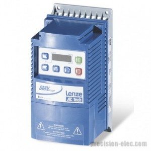
    1. Eaton VFD Model Number
    2. VFD Serial Number
    3. Reason for Service
    4. Urgency (Rush Overtime or Standard)
    5. Visual Inspection of External Device

2.Diode and IGBT Tests –Eaton VFD Troubleshooting

Eaton VFD TroubleshootingWhen Eaton VFD Troubleshooting exceeds parameter changes, Precision Electric tests the input and output power sections of the Eaton VFD. This step is essential prior to applying power to the VFD unit. If for any reason there is a short on the input side or output side of the VFD, further damage can be caused to the unit if power is applied to it.

For this reason, Precision Electric uses meters to properly test the input and output power sections of the Eaton VFD prior to applying power to the actual unit. If a short is found, the unit can be disassembled and the cause of the short can be diagnosed and quoted for repair. If the repair is too costly, then a replacement is offered to the customer.

3. Power Up –Eaton VFD Troubleshooting

If the input and output power sections test healthy during this step of the Eaton VFD troubleshooting and repair process, Precision Electric will power up the unit and perform amp reading and output frequency tests. Precision Electric prefers to slowly increase power voltage to the unit until the rated input voltage of the VFD is achieved.

Depending on whether or not the VFD provides a display will determine what further action(s) will be taken. If display is unavailable, dis-assembly and diagnosis of the internal power supply of the control section of the VFD is likely necessary to further evaluate cause of failure and establish cost and lead time for the Eaton VFD repair.

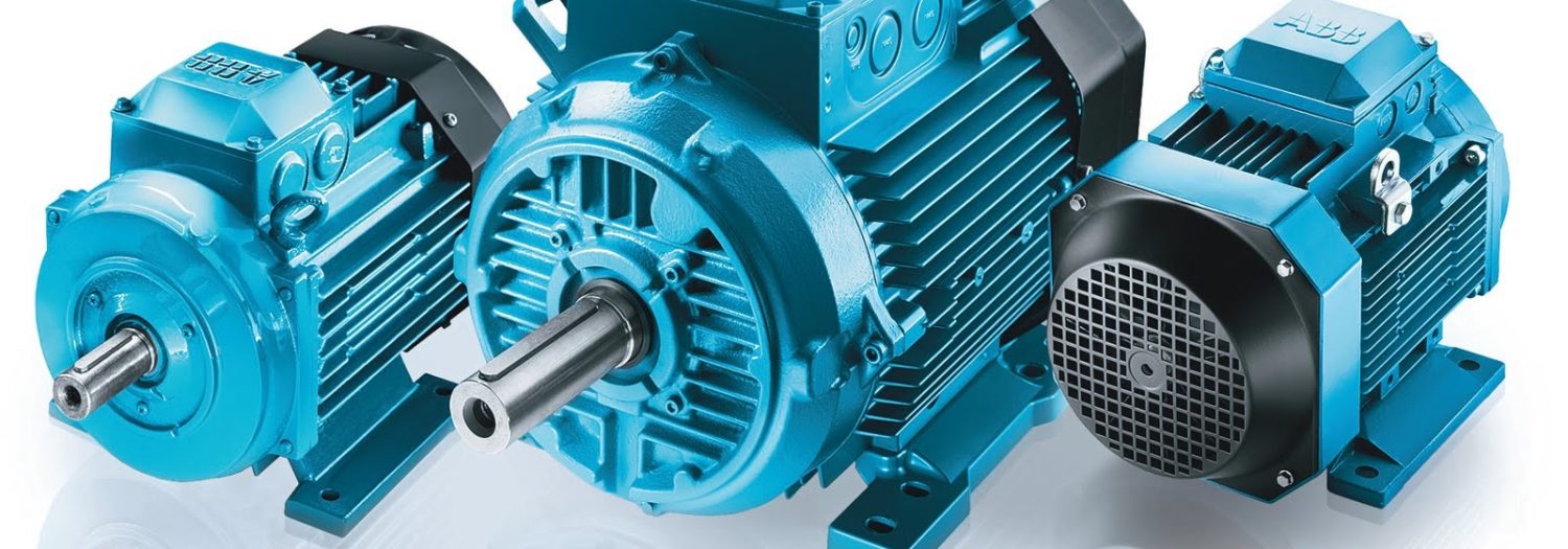
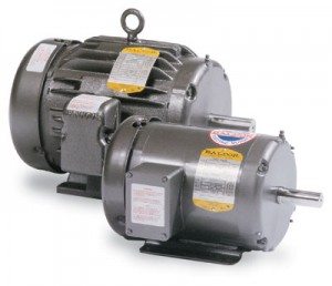
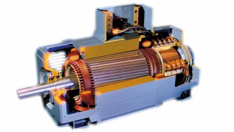
4. Run A Motor – Eaton VFD Troubleshooting

Eaton VFD TroubleshootingIf the previous three tests have passed during the Eaton VFD troubleshooting and repair process, then it is time to run a basic jog function of the VFD with a simple template program. Often when a VFD comes into our facility, we make sure to backup whatever program is currently stored in the VFD prior to inputting a template program and running a test procedure. This is to ensure we have a backup copy of the program.

The best method for backing up depends on the brand of drive, but after it has been backed up, we either reset the Eaton VFD to factory defaults through the keypad and recommission a basic start, stop and job application or closed loop if an encoder is involved. If the motor will not run, it will be necessary to check the output voltages and current ratings going to the motor to see if the VFD is functioning properly to rotate the motor.

5. Contact Customer – Eaton VFD Troubleshooting

At this point we have determined the cause of failure, estimated lead time and cost of the Eaton VFD troubleshooting and VFD repair. If the VFD has tested good entirely, then further underlying issues are communicated with the customer. This is when Precision Electricwill gather application specific information from the customer to establish whether or not it may be some outside issue associated with the system including, but not limited to, PLC communications, faulty IO, bad wiring or even bad cabling. There is no single way to do this step, as it depends on a wide variety of variables.

6. Send Service Tech – Eaton VFD Troubleshooting

If the customer cannot establish failure on any other aspect of the machine and the Eaton VFD troubleshooting tests appear to be good, then it may be necessary to send a Precision Electric field service technician on site to establish cause of failure. Precision Electricfield service technicians are trained to troubleshoot any issue ranging from standard VFD repair to advanced robotics, servo systems, electric motor issues and more. Precision Electric field technicians are trained to establish cause of failure and come up with solutions as quick as possible.

To learn more about Eaton VFD Troubleshooting or for Eaton VFD Repair Quotes, contactPrecision Electric, Inc.


VFD Manufacturers in the United States - ABB

VFD Manufacturers

When choosing VFD manufacturers for motor speed control equipment in production, it is recommended by Precision Electric to choose VFD manufacturers who offer extensive technical support for their products.Precision Electric recommends using VFD manufacturers in the United States, such asABBorLenze Americas. VFD manufacturers in the United States such as ABB and Lenze Americas have a reputable past for providing extensive technical support and troubleshooting for their VFD products.

USA VFD Manufacturers – ABB Low Voltage Drives

VFD Manufacturers in the United States - ABBABBlow voltage AC and DC VFD products are manufactured in the United States and are used across all industries and applications.ABBVFD products offer application specific functionality control for different types of motors as well as flexible connectivity to automation networks. ABB VFD products, inverters and converters are proven and reliable solutions backed by global production and life cycle services.

ABB VFD products provide scalable motor control from standard to demanding applications for a wide range of industries, especially in the process industries such as pulp and paper, metals, mining, cement, power, chemical, oil, gas, and more.

ABB VFD products are packed with advanced drive technology developed by ABB engineers and are capable of tackling even the most demanding requirements. A wide voltage and power range with various drive configurations and options enable one drive platform to be used for all needs.Precision Electric works closely with VFD manufacturers such as ABB.

Precision Electric offers retrofit solutions with the integration ofABBlow voltage VFD products to increase production time, and to increase energy efficiency for manufacturers across the nation. Precision Electric also offers ABB low voltage VFD distribution, technical telephone support, repair services and certified ABB VFD start up solutions. The ABB VFD Certified Start Up adds an extra one year warranty to anyABBVFDproduct that is installed by qualified Precision Electric service technicians.

USA VFD Manufacturers – Lenze Americas

VFD Manufacturers in the United States - Lenze AmericasLenze AmericasVFD products are manufactured and stocked in the United States.Lenze AmericasVFD and automation technology is used in a wide variety of industries; including materials handling, packaging industry, robotics and automotive. Lenze Americas products are carefully coordinated and matched, and can be combined as required to provide the right solution for production needs. Lenze Americas automation solutions with integrated software and system engineering, and a global customer service, makes Lenze Americas a leader in their industry.

Lenze Americas reliability combined with the quality of their products and services consequently increases the productivity of industrial manufacturing. Precision Electric has been working with Lenze Americas for over 25 years. Precision Electric offers Lenze VFD retrofit solutions to industrial manufacturers to increase energy efficiency and production for manufacturers across the nation. Precision Electric offers Lenze VFD repair services, distribution, and technical support forLenze Americasproducts.

Precision Electric aims to increase production time, while maximizing energy efficiency to manufacturers across the nation.ContactPrecision Electric today for free VFD Repair or VFD Replacement Quotes.


Excellent Versus Horrible Packaging When Shipping A VFD

Shipping A VFD

When Shipping A VFD, These Are Examples Of Perfect Packaging Versus Terrible Packaging.

Shipping a VFD (variable frequency drive) safely is important because electronic components can be easily damaged due to poor packaging. When shipping a VFD, the first step to safely package the VFD is to locate an appropriatesize box for everything you intend to ship. When using larger boxes, keep in mind this will mean higher shipping fees from the carrier, and large boxes are unnecessary if you’re shipping small items.

When shipping a VFD, always either use a box supplied by the VFD manufacturer, specifically designed for the VFD, or a cardboard box with thick sidewalls that will not break during shipment.Once an appropriate box has been located, gently place the items in the box and use plenty of packaging materials within the box to keep the VFD safe during shipment. You can use Styrofoam, newspaper, bubble wrap, or any other type of shipping material that will keep the VFD protected within the box during shipment.Once the variable speed drive has been safely boxed up, seal the box with clear shipping tape. Masking tape and duct tape are not recommended and will not be accepted by most shipping carriers. Clear packaging tape is easy to find and holds cardboard better.

Precision Electric receives VFD Drives that are damaged during shipping nearly every day, but for the most part, VFD Drive users are aware that it’s important to package equipment safely when shipping a VFD, no matter how far of a distance the drive will be shipping. Call Precision Electric for VFD Drive repair quotes or variable speed drive replacement quotes.


Benefits of Using a Variable Speed Drive

Benefits of Using a Variable Speed DriveApproximately one third of the world’s electrical energy is supplied by electric motors in fixed-speed centrifugal pump, fan, and air compressor applications. This proves thatsignificant energy efficiency improvement opportunities are available by applying variable speed drives to electric motors.

Variable speed drives have over the past decade allowed to become a cost efficient way to reduce energy costs and increase system production efficiency. Today variable speed drive manufacturers around the globe are finding more ways to benefit production processes by applying variable speed drives to manufacturing equipment .

Variable speed drives can reduce energy costs up to 50% by speed reduction on applications where the full speed (RPM) of the electric motor is not required.This energy savings is often significant enough to pay for the variable speed drive within a couple of months.

Variable Speed Drive Applications

Benefits of Using a Variable Speed DriveVariable speed drives are used in many applications such as swimming pool pumps, air compressors, conveyor belts, lathes, mills, food processing production lines, waste water treatment pumps, HVAC fans and blowers, and many more applications in the industrial manufacturing world. Variable speed drivesare often used in manufacturing facilities to increase or decrease the acceleration and deceleration times on alternating current (AC) motors. Adjusting the acceleration and deceleration timeon an AC motor can add years to the lifespan of an AC motor, and can also improve efficiency on production demands. Variable speed drives can also provide the ability to be programmed to control the frequency of starting and stopping an AC motor.This ability provides a means by which an AC electric motor is only operating when needed for the equipment it’s rotating. AC electric motors have a longer lifespan if they are not continuously operating when they don’t need to be.

Variable speed drives have an average lifespan of up to about 8 years from fractional horsepower through about 10 horsepower, but larger horsepower drives have a longer lifespan which creates a market for manufacturers to use variable speed drive repair centers. Variable speed drive repair centers work closely with manufacturers to keep production at a maximum while reducing production downtime.To learn more about variable speed drives or for variable speed drive repair and replacement quotes, contact Precision Electric, Inc.


ABB Frequency Converters

ABB Frequency Converters are used to change the frequency and magnitude of the constant grid voltage to a variable load voltage. Frequency converters are especially used in variable frequency AC motor drives.

Figure 1 shows the behavior of an induction motor with several motor input voltages. The bold blue curve represents the electrical torque as a function of rotor speed when the motor is connected directly to a constant supply network. The blue portion of the torque curve shows the nominal load region (-1+1 [T/TN]), which is very steep, resulting in low slip and power losses. Similar motor torque behavior with other motor input frequencies can be achieved by feeding the induction motor with a frequency converter and keeping the ratio of the magnitude and frequency of the motor voltage constant. As a result, the shape of the torque curve remains unchanged below the nominal speed (constant-flux region -1+1 [n/nN]). In the field weakening region the motor voltage is at its maximum and kept constant, resulting in the torque curves being flattened.

ABB Frequency Converters Figure 1Fig. 1. Operation principle of the frequency converter fed induction motor.

ABB Frequency converters can be classified according to their DC circuit structure to voltage-source (Fig. 4), current-source (Fig. 3) and direct converters (Fig. 2). With a voltage-source converter the variable frequency and magnitude output voltage is produced by pulse-width modulating (PWM) the fixed DC voltage, whereas with a current-source converter the output voltage is produced by modulating the fixed DC current. With a direct frequency converter the variable output voltage is formed directly by modulating the constant input voltage. At low voltage applications (<1000 V) the voltage-source topology is mainly used.

ABB Frequency Converters Figure 2Fig. 2. Main circuit of the direct converter

ABB Frequency Converters Figure 3Fig. 3 Main circuit of the current-source converter

Fig. 4 shows a typical voltage source frequency converter structure where a constant DC voltage is formed by using an input diode rectifier. The output voltage with variable frequency and magnitude is produced by pulse-width modulating the inverter bridge. In more sophisticated frequency converters the input diode bridge can be replaced with a PWM bridge enabling a higher DC voltage, reactive power control, nearly sinusoidal supply network currents and regenerative operation of the inverter.

ABB Frequency Converters Figure 4Fig. 4. Main circuit of the commonly used voltage-source frequency converter.

Fig. 5a shows the operation of the inverter bridge with two different output voltages. The desired output voltage is achieved by changing the width and polarity of the output voltage pulses. The higher the instantaneous value of the output voltage, the wider the output voltage pulse needed. Although the output voltage contains a lot of high order harmonic voltages due to the PWM, the motor current is nearly
sinusoidal since the motor inductances filter out the high order current harmonics.

Fig. 5b shows the construction of negative voltage pulses, circled in Fig.5, during one PWM period. The graphic on the right shows the switching states of the phases and the resulting U-V voltage. The graphic on the left shows the space vector presentation of the eight switching states of the voltage-source converter. These switching vectors are commonly used to achieve PWM (vector modulation). The + and - signs mean that the phase is connected to the positive or negative rail of the DC link respectively.

ABB Frequency Converters Figure 5Fig. 5a and 5b Operation of the voltage-source inverter with two different output voltage references and the principle of pulse width modulation.

To learn more about ABB Frequency Converters or to download technical information, visit the ABB Website.


Information References: